Table of Contents
Advertisement
Quick Links
Advertisement
Table of Contents

Subscribe to Our Youtube Channel
Related Manuals for PCE Instruments PCE-POE 10


Summary of Contents for PCE Instruments PCE-POE 10
- Page 1 User Manual PCE-POE 10 Cable Tester User manuals in various languages (français, italiano, español, português, nederlands, türk, polski, русский, 中文) can be found by using our product search on: www.pce-instruments.com Last change: 3 February 2021 v1.0 © PCE Instruments...
-
Page 2: Table Of Contents
Main menu ........................4 PoE switch test......................... 4 PoE power test ......................... 6 Cable test functions ......................6 Power test function ......................8 Loop-back test........................8 Lighting function ....................... 8 Settings ..........................9 Warranty ....................10 Disposal ....................10 © PCE Instruments... -
Page 3: Safety Notes
We expressly point to our general guarantee terms which can be found in our general terms of business. If you have any questions please contact PCE Instruments. The contact details can be found at the end of this manual. © PCE Instruments... -
Page 4: Specifications
Connection RJ45 Function Cable test functions Delivery scope 1 x PCE-POE 10 transmitter 1 x PCE-POE 10 receiver 3 x 1.5 V AAA battery 1 x RJ45 test cable 1 x RJ11 test cable 1 x RJ11 test adaptor with alligator clip... -
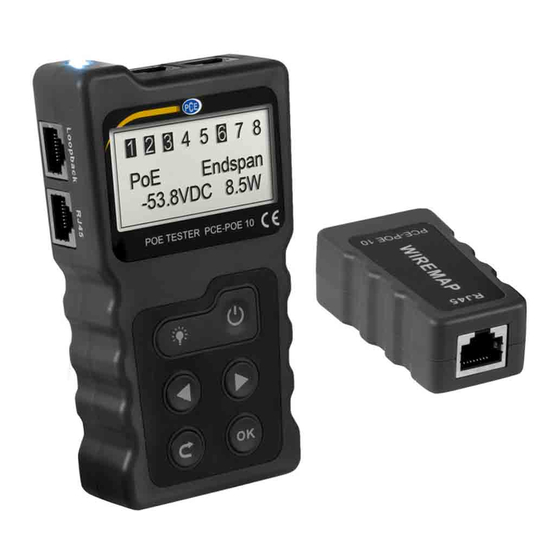
Page 5: Device Description
2. PoE test connection 7. DC Out 12.OK 13.RJ45 connection 3. RJ-45 loop back connector 8. DC In for cable test functions 4. RJ-45 connector 9. Arrow key left for cable test functions 5. Light ON/OFF 10.Back key © PCE Instruments... -
Page 6: Main Menu
Connect a network cable between the PoE switch and the PCE-POE 10 (RJ45 connection 2, see above). The correct connection is signalled by means of the measured voltage on the display of the PCE-POE 10. Press "Enter" to start the test. The result is then displayed on the screen. 3.2.1... - Page 7 POE switch to be tested. Disconnect the cable connection of these devices and repeat the test. 3.2.4 Unconnected If the error message "Unconnected" appears on the display, no compatible POE switch has been detected. © PCE Instruments...
-
Page 8: Poe Power Test
The connected network cable can be an 8-core UTP or a 9-core STP network cable. If the cables are intact, one of the following screens will appear on the PCE-POE 10: 3.4.1... - Page 9 (cores 1&8 and 5&6 are crossed) 3.4.4 Cable open If the message "Cable open" appears on the display of the PCE-POE 10, this may be due to the following reasons: 1. The connected network cable actually has a breakage. 2. The connected network cable is not correctly connected to the transmitter.
-
Page 10: Power Test Function
This function can be used to measure the power consumption of the PSE or PD. To do so, use sockets 7 and 8 on the right-hand side of the PCE-POE 10. The mains adaptor of the PSE or PD is connected to the "DC IN" input and the PSE or PD itself to the "DC OUT" output. -
Page 11: Settings
The automatic power-off of the meter can be set at intervals of 15, 30 and 60 minutes or disabled by selecting "off". 3.8.4 Display contrast The display contrast can be changed between 20 and 35 with the arrow keys. 3.8.5 Software version This menu item displays the hardware / software version of the unit. © PCE Instruments... -
Page 12: Warranty
For countries outside the EU, batteries and devices should be disposed of in accordance with your local waste regulations. If you have any questions, please contact PCE Instruments. © PCE Instruments... - Page 13 PCE Instruments contact information Germany France Spain PCE Deutschland GmbH PCE Instruments France EURL PCE Ibérica S.L. Im Langel 4 23, rue de Strasbourg Calle Mayor, 53 D-59872 Meschede 67250 Soultz-Sous-Forets 02500 Tobarra (Albacete) Deutschland France España Tel.: +49 (0) 2903 976 99 0 Téléphone: +33 (0) 972 3537 17...
Need help?
Do you have a question about the PCE-POE 10 and is the answer not in the manual?
Questions and answers