Table of Contents
Advertisement
Available languages
Available languages
Quick Links
Doepke
Inhaltsverzeichnis
1. Allgemeines.............................. 2
2. Kodierung................................. 2
3. Inbetriebnahme ........................ 3
4. Anzeigen .................................. 3
5. Technische Daten .................... 3
6. Garantie ................................... 4
Diagram.................................... 8
Dupline
Rollladensteuergerät DRO 4
Shutter Control Unit DRO 4
Bedienungsanleitung
Operating Instructions
3931210/03/05/E
Table of Contents
7. General Information ................. 5
8. Coding ...................................... 5
9. Putting into Service .................. 6
10. Indicators.................................. 6
11. Technical Data ......................... 6
12. Guarantee ................................ 7
13. Anschlussschema / Connection
Diagram.................................... 8
Advertisement
Table of Contents

Related Manuals for Doepke Dupline DRO 4


Summary of Contents for Doepke Dupline DRO 4
- Page 1 Doepke Dupline Rollladensteuergerät DRO 4 Shutter Control Unit DRO 4 Bedienungsanleitung Operating Instructions Inhaltsverzeichnis Table of Contents 1. Allgemeines......2 7. General Information ....5 2. Kodierung......... 2 8. Coding ........5 3. Inbetriebnahme ......3 9. Putting into Service ....6 4.
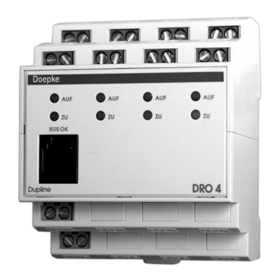
- Page 2 Doepke Bedienungsanleitung Dupline Rollladensteuergerät DRO 4 1. Allgemeines Das Rollosteuergerät DRO 4 ist eine Komponente des Dupline Installationssystems und ermöglicht das Schalten von vier unabhängigen Rollomotoren oder auch Markisen- oder Dachfensterantrieben. Die Motoren können dabei an unterschiedlichen Stromkreisen betrieben werden. Die Kontakte für Auf und Ab sind elektronisch und mechanisch im Ge- rät sowie softwaremäßig im System verriegelt.
- Page 3 Doepke Busausfall die Fahrtrichtung „AB“. 3. Inbetriebnahme Die Installation darf nur von einer autorisierten Fachkraft vorgenommen werden. Bei der Installation ist das Anschlussschema zu beachten. Alle anzuschließenden Leitungen müssen spannungsfrei sein. Folgende Tabelle zeigt die Anschlussbelegung: Klemme Beschreibung Klemme Beschreibung 1.1/1.5...
- Page 4 Doepke Min. Typ. Max. Nennstrom (pro Ausgang) cos ϕ = 0,6 - 1 Leistungsfaktor Betriebsspannung Nennbetriebsspannung 21,5 VDC 24 VDC 26,5 VDC Stromaufnahme 3 mA 45 mA Erlaubte Brummspannung 100 mV Anschlüsse Art Zugbügelklemmen 0,4 mm ∅ Klemmbereich 2,5 mm²...
- Page 5 Doepke Operating Instructions Dupline Shutter Control Unit DRO 4 7. General Information The shutter control unit DRO 4 is a component of the Dupline building management sys- tem and allows switching up to four independent shutters as well as sunblinds or electri- cal dormers.
- Page 6 Doepke 9. Putting into Service Only an authorized expert is allowed to carry out the installation. When installing, the connection diagram has to be observed. All conductors that shall be connected have to be free of voltage. Following table shows the connections:...
- Page 7 Doepke Min. Typ. Max. Rated current / load capacity cos ϕ = 0.6 - 1 Power factor Operating Voltage Rated operating voltage 21.5 VDC 24 VDC 26.5 VDC Current input 3 mA 45 mA Ripple voltage 100 mV Terminals Type Strain-relief clamps 0.4 mm ∅...
- Page 8 Doepke 13. Anschlussschema / Connection Diagram L IN1 L IN1 L IN2 L IN2 L IN3 L IN3 L IN4 L IN4 Doepke BUS OK BUS OK DRO 4 Dupline Dupline + Dupline - +24V DC 0V DC Sollten Sie Fragen zu diesem Produkt...
Need help?
Do you have a question about the Dupline DRO 4 and is the answer not in the manual?
Questions and answers