
Related Manuals for Vimar 21125


Summary of Contents for Vimar 21125
- Page 1 Installer manual 21125 Electronic control unit, 8 non-polarised inputs, 7 solid-state outputs for non-polarised contacts...
-
Page 3: Table Of Contents
Contents 1. General description............................................4 2. Characteristics.............................................4 3. Connections..............................................5 3.1 Inputs...............................................5 3.2 Outputs..............................................8 4. RGB LEDs and pushbuttons........................................9 4.1 RGB LEDs............................................11 4.2 Push buttons............................................11 5. Configuration of the device........................................11 5.1 Setting the colours of the LEDs......................................11 5.2 Device setup............................................12 5.3 Factory reset............................................13 6. -
Page 4: General Description
General description - Characteristics 1. General description Electronic unit, 8 non-polarised inputs, 7 solid state outputs for non-polarised contacts, configurable RGB LED backlighting, 9-32 Vdc power supply, for external/internal hotel room or cabin applications, to be completed with Eikon Tactil labels and cover plate - 3 modules. 2. -
Page 5: Connections
The inputs are not polarised and are isolated from the device's supply voltage by functional isolation (non-reinforced); this allows the connection of input signals with reference voltages that differ from the supply voltage of the 21125 electronic control unit, provided they have SELV power supplies. - Page 6 Connections Example 1: Connection via contacts that close to the power supply negative (-) (most frequently used case). The inputs can be connected to the device's power supply negative (-) by means of a switch. Open collector outputs of a third-party device can be used as switches, provided it is checked beforehand that these outputs have appropriate maximum voltage and current values.
- Page 7 Example 3: Connection with a signal generator with different voltage references. The inputs can be connected directly to a third-party device that provides an output with voltage and current values compatible with the inputs of the 21125 electronic control unit.
-
Page 8: Outputs
Connections 3.2 Outputs The outputs connector is of the type JST PHR-9. 30 cm The outputs are non-polarised solid state (volt-free contact) and are all referred to the common on pin C. The outputs can be used to control signals but are not suitable for controlling loads (for example, thee coils of large relays or contactors, high-power LED lights, etc.). •... - Page 9 Example 2: Connection of small indicator lights. The outputs can be connected to indicator lights with characteristics compatible with the maximum voltage and current values of the 21125 electronic control unit. The outputs common is to be connected directly to the power supply positive (+).
- Page 10 Connections Typical example of room connections (inputs and outputs). OUTSIDE ROOM (IN8 connected) INTERNAL ROOM +12VDC PRESENCE RELAY −V 2046 Adj. MEAN WELL Art. 01831.1 Art. 20380 230 V~ Note: The IN7 input is not connected; the LED colour has been set manually using the device.
-
Page 11: Rgb Leds And Pushbuttons
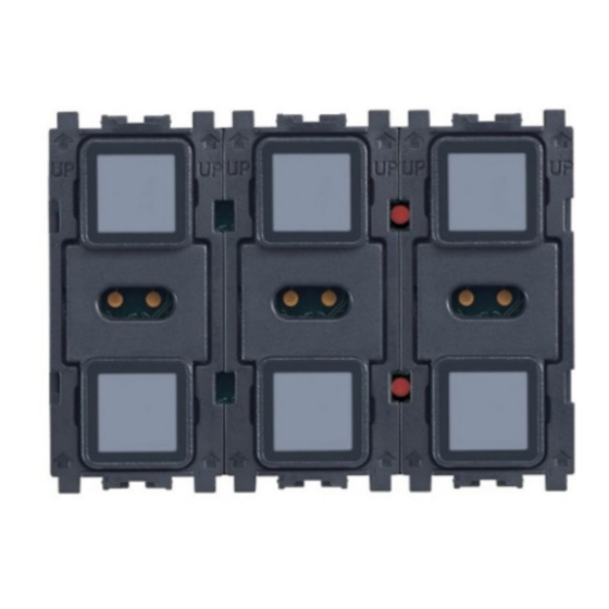
4.2 Pushbuttons When the cover plate is not fitted, the 21125 electronic control unit presents six physical pushbuttons (shown in blue) and two configuration pushbuttons (shown in red). Once the cover plate has been fitted to the control, the 6 touchscreen buttons (shown in blue) can be used independently of each other. -
Page 12: Device Setup
Device configuration 5.1.1 Configuration via input 7 By providing a signal at input 7 and modulating the pulse width, it is possible to configure the colours of all the LEDs, as indicated in the table below. Modulation % LED colour 0 - 13 Custom colour saved to memory (see paragraph 5.1.2) 14 - 27... -
Page 13: Factory Reset
Operation • The LEDs of the central module indicate the sensitivity of the touchscreen when the device is used in combination with a cover plate; if the upper centre LED is on, sensitivity is high, and if the lower centre ED is on, sensitivity is low. To select the desired behaviour, simply press the relative pushbutton (the two central pushbuttons are mutually exclusive). -
Page 14: External Room
Operation 6.1.1 Standby The colour and brightness of the LEDs is that set during configuration. ■ Lower left LED: - Off if the DO NOT DISTURB signal is not active. - On at set brightness for standby if the signalling is active. ■... -
Page 15: Installation Rules
Installation rules - Regulatory compliance ■ lower left LED (MAKE UP ROOM): - Off if input I5 is not active. - On at set brightness for standby if I5 is active. ■ upper central LED: always off. ■ lower central LED (door bell): - Off if input I6 is active (DO NOT DISTURB). - Page 16 Viale Vicenza 14 36063 Marostica VI - Italy 21125IEN 02 1901 www.vimar.com...
Need help?
Do you have a question about the 21125 and is the answer not in the manual?
Questions and answers