Table of Contents
Advertisement
Quick Links
INSTR,INSTL,2GIG-WMT1-345 - P/N: 10013348 X1 - INK: BLACK - MATERIAL: 16 LB. MEAD BOND - SIZE: 8.5000" X 11.000" - TOL. +/- 0.125"- SCALE: 1-1 - FOLDING : FOLD 4 X TO FINAL SIZE 2.125" X 2.750"- FINISH WITH LOGO SHOWING - SIDE 1 OF 2
2GIG-WMT1-345
WALL-MOUNT HELP BUTTON
INSTALLATION INSTRUCTIONS
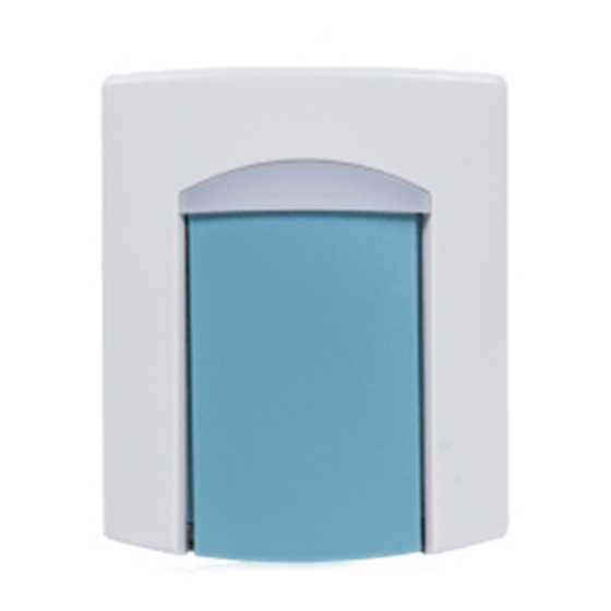
The Wall-Mount Help Button (2GIG-WMT1-345) is a battery-powered transmitter, designed
for use with the provided panel. The transmitter is referred to as the "Help Button." The
panel is the "Console." Both the Help Button and the Console together are referred to as a
"System."
The Help Button is a supervised transmitter designed for use with compatible 345 MHz
receivers (security panels, PERS consoles, and Libris Smart Cradles). The unit ships with
a mounting plate, two mounting screws, four adhesive-backed table-top "feet", and an
alternate red activation button printed with bold HELP text.
2-COLOR SIGNAL
2GIG-WMT1-345
INDICATOR
WALL-MOUNT
GREEN = BATTERY OK
HELP BUTTON
RED = BATTERY LOW
AQUA COLOR
BUTTON
Figure 1. Help Button Features and Accessory Parts
For further information regarding testing recommendations, safety precautions, use, and
operation of the Help Button and the Console, consult the more detailed instructions
included with the Console and also found in the literature section of the following link:
www.nortekcontrol.com/manual_list1.php
Help Button Mounting Options
The mounting plate snaps onto the back of the Help Button. It can be used to attach the unit
to a wall or other mounting surface. For stationary applications, use the two screws supplied
to affi x the mounting plate, then attach the Help Button to the plate. For table-top use, stick
the four adhesive "feet" onto the mounting plate, then attach the Help Button to the plate.
HOOK TOP OF HELP BUTTON
ONTO THE BRACKET TABS
ATTACH THE WALL
MOUNT BRACKET
WITH TWO SCREWS
FOR NON-WALL MOUNT APPLICATIONS,
STICK THE FOUR ADHESIVE "FEET"
ONTO THE MOUNTING BRACKET
Figure 2. Help Button Mounting Bracket
Box Contents
Verify that the package includes the following:
• 1 - Wall-Mount Help Button transmitter
• 1 - Alternate red button with bold HELP text
• 1 - Mounting Plate
• 2 - Mounting Screws
• 4 - Adhesive-backed Table-top Feet
PRINTER'S INSTRUCTIONS:
ALTERNATE RED
HELP BUTTON
MOUNTING
PLATE
TABLE-TOP
MOUNTING
FEET (4)
SCREWS (2)
SWING HELP BUTTON
ONTO BRACKET
TO REMOVE
HELP BUTTON
PRESS THE TAB ON
THE BRACKET
Alternate Red HELP Button Installation
The Help Button's standard aqua colored button can be exchanged for the red button printed
with bold HELP text included with the unit. See the fi gure below for instructions.
Figure 3. Exchanging the Unit's Button
OPERATION
Initial Activation of Help Button & General Use
When your Help Button arrives, you must immediately call the monitoring service provider
that provided the Help Button to you and ask them to confi rm that the Help Button has been
programmed and is properly transmitting.
The Help Button also comes with a Battery Supervision Feature, aimed to identify Systems
that are not functioning, either because the battery has died, or because the Console
connection was lost. To turn the Battery Supervision Feature ON, you must press
the Help Button and hold it down for 2 seconds. When you release the Help Button,
its LED indicator fl ashes GREEN to indicate that the Battery Supervisor Feature is
working and the Help Button is active.
Pressing the button should also initiate a two-way voice communication through the
Console with your monitoring services provider. If the two-way voice communication
is not initiated when you press the button, you should call your monitoring service
provider immediately to report the problem.
Once activated, the Help Button should be tested weekly, as further explained in the following
You must be within range of the Console in order for the Help Button to communicate with
the Console, for either emergency or Help Button low battery report.
The operating range of the Help Button is limited. The exact range of a System
depends on the type of Console and other variables, such as the local radio frequency
environment. Depending on these factors, range is expected to be approximately 300
to 500 feet line of sight. Range can be reduced by walls and other barriers. You can
ensure that you are in range at any time by pressing the button to test the system.
Please refer to the instructions included with your Console and also found in the
literature section of the following link for more information regarding the range of
your System:
www.nortekcontrol.com/manual_list1.php
The battery contained in the Help Button is not replaceable. When the battery in the Help
Button is low, the LED indicator on the Help Button will display RED, and it is designed to
send a signal to the Console, which will communicate to your monitoring service provider that
your battery is low. Your monitoring service provider should then contact you to coordinate
delivery of a replacement Help Button. As a precautionary measure, in order to ensure
that the battery does not deplete before you receive a replacement Help Button, if you
see that the light on your Help Button is RED, you should contact your monitoring
service provider to arrange for a replacement Help Button as soon as possible - DO
NOT WAIT for the monitoring service provider to contact you.
Copyright ©2016 Nortek Security & Control LLC
1
TWIST A COIN OR SCREWDRIVER IN
THE SLOT ON TOP OF HELP BUTTON
TO OPEN THE CASE
2
REMOVE THE CASE TOP, BUTTON,
AND SILICONE SEAL
EXCHANGE THE BUTTON WITH THE
3
ALTERNATE BUTTON
4
REVERSE STEPS TO REASSEMBLE
1
Advertisement
Table of Contents

Subscribe to Our Youtube Channel
Related Manuals for Nortek Security & Control Numera 2GIG-WMT1-345

Summary of Contents for Nortek Security & Control Numera 2GIG-WMT1-345
- Page 1 PRINTER’S INSTRUCTIONS: INSTR,INSTL,2GIG-WMT1-345 - P/N: 10013348 X1 - INK: BLACK - MATERIAL: 16 LB. MEAD BOND - SIZE: 8.5000” X 11.000” - TOL. +/- 0.125”- SCALE: 1-1 - FOLDING : FOLD 4 X TO FINAL SIZE 2.125” X 2.750”- FINISH WITH LOGO SHOWING - SIDE 1 OF 2 2GIG-WMT1-345 WALL-MOUNT HELP BUTTON Alternate Red HELP Button Installation...
- Page 2 PRINTER’S INSTRUCTIONS: INSTR,INSTL,2GIG-WMT1-345 - P/N: 10013348 X1 - INK: BLACK - MATERIAL: 16 LB. MEAD BOND - SIZE: 8.5000” X 11.000” - TOL. +/- 0.125”- SCALE: 1-1 - FOLDING : FOLD 4 X TO FINAL SIZE 2.125” X 2.750”- FINISH WITH LOGO SHOWING - SIDE 2 OF 2 2GIG Large Help Bu on Instruc ons Additional Testing Information SPECIFICATIONS...
Need help?
Do you have a question about the Numera 2GIG-WMT1-345 and is the answer not in the manual?
Questions and answers