Sign In
Upload
Download
Table of Contents
Contents
Add to my manuals
Delete from my manuals
Share
URL of this page:
HTML Link:
Bookmark this page
Add
Manual will be automatically added to "My Manuals"
Print this page
×
Bookmark added
×
Added to my manuals
Manuals
Brands
Neat Manuals
Control Unit
INKA
Technical handbook
Neat INKA Technical Handbook
Hide thumbs
1
Table Of Contents
2
3
4
5
6
7
8
9
10
11
12
13
14
15
16
17
18
19
20
21
22
23
24
25
26
27
28
29
30
31
32
33
34
35
36
page
of
36
Go
/
36
Contents
Table of Contents
Bookmarks
Table of Contents
Table of Contents
1 Introduction
About this Manual
Overview
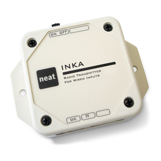
INKA - Radio Transmitter for Wired Inputs
IOR - Radio Transceiver for Wired I/O
REPO - Radio Repeater
LINK - Radio Receiver
Connectors
Inka
Ior
Repo
Link
Power Switch
Mounting Holes
Batteries
Inka
Ior, Repo & Link
AC/DC Adapter
Inputs: INKA and IOR
Outputs: IOR, REPO and LINK
2 Programming / Configuration
PC Programming
NPU - NEAT Programming Unit
IOR Programmer, Start Screen
IOR Programmer, Radio Input Tab
IOR Programmer, Wired Input Tab
IOR Programmer, Preferences Tab
Jumper Configuration
Jumper Settings - Overview
Input Mode for Wired Input 1-3
Input Mode for Wired Input 4-5
Receive All Codes
Maximum Number of Hops
Transmission Delay
Output Mode
Power Mode
3 Event Handling
Radio Reception: IOR, REPO and LINK
Radio Codes
Connecting Alarm Transmitters to IOR, REPO and LINK
Fixed Input
Receive All Codes
Wired Input: INKA and IOR
Digital Input
Analog Input
Out Passage Delay
Wired Output: IOR, REPO and LINK
Pulse Activation Time
Relay Action When Wired Input Is Trigged
Relay Action When Radio Message Is Received
Radio Transmission: INKA, IOR and REPO
ID Code in Transmitted Radio Message
Alarm Type for Transmitted Alarm
Number of Transmissions - Radio Packages
Disable Acknowledge
In Passage Delay
Transmission Delay
Maximum Number of Hops
Same Code Inhibit Time
Power Mode
Battery Charge Duration
Technical Alarms
Radio Test Alarm
Battery Alarm: INKA, IOR and REPO
Mains Failure
Mains Return
Advertisement
Quick Links
1
Inka - Radio Transmitter for Wired Inputs
2
Ior - Radio Transceiver for Wired I/O
3
Repo - Radio Repeater
4
Inka
Download this manual
7
IOR Family
Technical Handbook
Table of
Contents
Previous
Page
Next
Page
1
2
3
4
5
Advertisement
Table of Contents
Need help?
Do you have a question about the INKA and is the answer not in the manual?
Ask a question
Questions and answers
Related Manuals for Neat INKA
Transceiver Neat IOR User Manual
Radio transceiver for wired i/o (16 pages)
Control Unit Neat REPO Technical Handbook
(36 pages)
Control Unit Neat LINK Technical Handbook
(36 pages)
This manual is also suitable for:
Ior
Repo
Link
Table of Contents
Print
Rename the bookmark
Delete bookmark?
Delete from my manuals?
Login
Sign In
OR
Sign in with Facebook
Sign in with Google
Upload manual
Upload from disk
Upload from URL


Need help?
Do you have a question about the INKA and is the answer not in the manual?
Questions and answers