Advertisement
Quick Links
Advertisement

Related Manuals for Elma Instruments TDR-44

Summary of Contents for Elma Instruments TDR-44
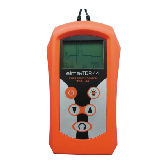
- Page 1 CABLE FAULT LOCATOR Handheld Graphical TDR Model TDR-44 Operation Manual...
-
Page 2: Table Of Contents
Contents page 1. Introduction 2. Batteries 3. Safety Rules 4. Operating Instructions 5. Type of cable fault 6. Specification 7. Accessories 8. Repair and servicing 9. Warranty... -
Page 3: Introduction
WARNING: The safety condition is not to connect Fault locator to the energised cable, even this equipment does not generate any hazardous voltage to other circuit. 1. Introduction The Fault Locator is a pulse-echo cable test set which provides a visual indication of cable faults such as open circuits, shorts and bad connections up to 3000m (9500 ft.) on metallic cables. -
Page 4: Safety Rules
3. SAFETY RULES Though this tester does not generate any hazardous voltages, to circuits to which it can be connected could not be dangerous. Always check that the circuit to be tested is de- energised before connecting the tester. Electrical circuits can be dangerous if there is a lack of caution and /or safety practices. Do not use leads, probes or clips that are damaged or in need of repair with the tester. - Page 5 Operates key Power on/off key Switch on and off the unit. The unit have auto powering down If the key is not depressed 5 minutes Menu select key This allows the setting up of the Propagation Velocity Factor, Cursor Control, Range select and Measure unit via the up-down arrow keys. Backlight key This illuminates backlight to the display when depressed.
- Page 6 4.2 FAULT LOCATION ON CABLES WITH KNOWN PROPAGATION VELOCITY FACTOR In many cases, the cable layout and characteristics are known and the fault location and analysis should be simple and quick. Under these conditions, the procedure is as follows: Disconnect the faulty pair from service if possible. Connect the faulty pair to the line terminals of the tester.
-
Page 7: Type Of Cable Fault
4.3 DETERMINING UNKNOW PVF If the cable dielectric / propagation velocity factor is not known, the PVF setting can be determined from using a known length of the same type of cable or distance to a known point in the same cable a) Measure the apparent distance to end or known point with any PVF value, using the normal procedure as section 4.2 above b) Press Menu Select Key to PVF mode... - Page 8 5.2 OPEN CIRCUITS Opens are caused when one or both. Conductors of a pair are disconnected or broken. The reflection is upward polarity pulse, Fig.2 Open sheaths are caused by a break in the cable sheath. To locate such faults, connect the line terminals to the sheath and to as many cable conductors as possible to reduce the clutter on the screen.
- Page 9 5.5 Low insulation and Water ingress These faults are due to contamination of the insulation medium by moisture ingress through a cable. This gives a reflection like short conductor fault pulse, where the moisture starts, followed by a small open-type fault pulse where the moisture ends. In some cases, where the moisture increases gradually with distance, these fault pulses broaden out into a gentle shell or dip in the horizontal trace, Fig 5.
-
Page 10: Specification
5.8 Load coils Load coil are used on telephone lines to increase the line inductance, so improving the transmission characteristics of long lines. TDR generally will not test pass load coil so the inductive load coils appear as open circuits to the cable fault locator, so the upward reflection will be displayed as Fig 8. Fig. -
Page 11: Accessories
7. Accessories 7.1 2 meters test lead Safety Plug 3 mm to Alligator Clip 7.2 Soft vinyl carry case 7.3 Operation manual 8. Repair and servicing This instrument is not a user serviceable item other than the replacement of batteries. In the unlikely event of failure please return to the nearest distributor or Manufacturer Manufacturer address: Pantong Technologies Co.,Ltd...
Need help?
Do you have a question about the TDR-44 and is the answer not in the manual?
Questions and answers