Table of Contents

Related Manuals for AmeriWater Heatsan 00HS208

Summary of Contents for AmeriWater Heatsan 00HS208
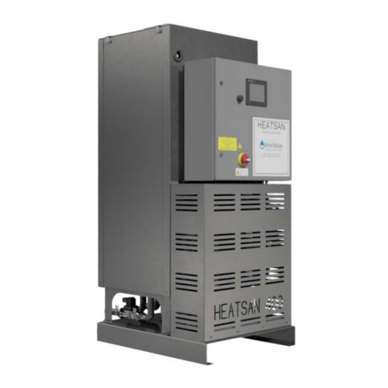
- Page 1 AmeriWater Operation & Maintenance Manual The Water Purification Specialists Heatsan Heat Sanitization System 3345 Stop 8 Rd, Dayton, OH 45414 | 800 535 5585 | www.ameriwater.com 98-0156 Rev G 98-0156G Manufactured With Pride in The USA...
-
Page 2: Table Of Contents
TABLE OF CONTENTS CONTACT DETAILS ....................3 HEALTH AND SAFETY ....................4 Explanation of symbols and references ........... 5 Additional safety requirements ..............5 Usage in accordance with intended purpose .......... 5 Operating staff ....................6 Bringing the system to a stop in the event of an emergency ....7 Safety information for maintenance tasks .......... - Page 3 Commissioning ..................17 OPERATING PROCEDURES ..................18 Operator Interface ..................18 Operation (levels of access) ..............18 Operation (password entry)..............19 Log In ....................19 Operation ....................19 Daily Defaults Menu ................. 19 System Set-up ..................22 Today Current Set-up menu ............23 Heatsan Immediate Start ..............
-
Page 4: Contact Details
1 CONTACT DETAILS For all service, spares and consumables enquiries contact: AmeriWater 3345 Stop 8 Rd Dayton, Ohio 45414 Tel No. 800-535-5585 (Or your local authorized AmeriWater dealer) Useful Telephone Nos. Tel No………………………………Contact Name:………………………………. Tel No………………………………Contact Name:………………………………. 98-0156 Rev G... -
Page 5: Health And Safety
If the unit’s performance becomes impaired and any remedial work appears to be outside the scope of this manual, then seek advice from AmeriWater, quoting the unit’s serial number (Refer to Section 1 Contact Details). The unit must not be disassembled in any way unless carried out by an AmeriWater technician or authorized trained personnel. -
Page 6: Explanation Of Symbols And References
Explanation of symbols and references This symbol refers to any immediate dangers. Failure to follow the specified procedure could result in serious personal Injury. Extreme caution should be observed Danger when conducting any activity where this symbol is shown. Work should be completed by a trained competent person. -
Page 7: Operating Staff
Installation of the unit will only be carried out by AmeriWater or an approved installation technician. If the unit is used in a manner not specified by AmeriWater or procedures not followed as detailed in this manual, the protection provided by this equipment may be impaired. -
Page 8: Bringing The System To A Stop In The Event Of An Emergency
Conversion or modification of the system is only permitted with the approval of AmeriWater. Original replacement parts authorized / supplied by the manufacturer enhance safety and ensure design performance. The use of unauthorized parts may void the warranty on the unit, impair its performance or compromise the safety of those operating it. -
Page 9: Warranty Claims And Liability
To obtain warranty service, notice must be given to the manufacturer within 30 days of the discovery of the defect. There are no warranties on the AmeriWater system beyond those specifically described above. All implied warranties, including any implied warranty of merchantability or of fitness for a particular purpose are disclaimed to the extent they might extend beyond the above periods. -
Page 10: Specification
3 SPECIFICATION The Heatsan Integrated hot water disinfection unit incorporates equipment to heat water received from a water purification system and circulate around a distribution loop at a controlled sanitizing temperature for a specified length of time. On completion of disinfection the water is then made available to be taken off to dialysis machines for their heat disinfect cycle. -
Page 11: Electrical Supply Requirements
Electrical Supply Requirements Electrical Supply* Operation** Current draw rating (amps) per phase 3-phase Heatsan / 16kW +E,208V, 60hz Recirculation Notes: * Circuit isolation of the incoming supply should be provided external to the unit. ** Maximum duty with one 9kW and two 3kW heaters on plus recirculation pump. -
Page 12: Environment
Note: The maximum number of dialysis machines that the unit can supply depends on the volume of hot water required per machine and the rate at which they draw water. So long as the total volume of water required does not exceed the maximum available for draw off and the maximum draw rate does not exceed the pump performance. -
Page 13: Process Description
4 PROCESS DESCRIPTION This section provides general information regarding the heat disinfection process utilized by the Heatsan unit. Operation General philosophy of operation: The unit can be configured to disinfect up to two distribution loops, either individually or together. The user can set for each day of the week which loop is to be disinfected and in what configuration. -
Page 14: Heating (Heatsan Operation)
During this stage the unit fills the tank with only the amount of permeate needed for the number of machines programmed in by the operator. This feature saves on power and water consumption. The heaters then raise the temperature to the tank preheat temperature and hold it until the timed Heatsan start period is reached. -
Page 15: Cool Down Period
Cool down period Once the water availability stage has timed out the system will proceed into automatic “Cool down”. The system will perform a series of tank drain downs and introduce cold RO permeate into the distribution loops until the return temperature on the system falls below the “maximum service temperature”... -
Page 16: Installation
5 INSTALLATION This section provides the recommended method of installation for the Heatsan unit. Environment The unit should be installed in a clean and dry, indoor, non-hazardous, ventilated environment (see Section 3.9). Unpacking When transporting the unit either by pallet truck or by forklift observe the centre of gravity markings and prevent from tipping. -
Page 17: Drain
Drain A suitable, unrestricted, drain is required, capable of handling the discharge flow of the Heatsan unit (see specification). The drain should be capable of accepting 203°F water. Overflow An unrestricted overflow must be provided which terminates with an air gap that conforms to any local or National regulations. The overflow pipework must be capable of withstanding water up to 203°F. -
Page 18: Installation Plan Layout
X-15 Heatsan to RO Interface, Power Supply Fault Installation Plan Layout Refer to Section 10.4 for suggested installation plan layout. Commissioning Commissioning of the Heatsan unit should only be carried out by either an AmeriWater technician or authorized trained personnel. 98-0156 Rev G... -
Page 19: Operating Procedures
Operation, for details of level of access available. Operation (levels of access) There are five levels of user access: LEVEL 0, 1, 2, 3, & 5 NB: Level 5 access is reserved for AmeriWater technical staff. User Level Password Access... -
Page 20: Operation (Password Entry)
Operation (password entry) Log In Screen Display Action When power is applied to the Heatsan unit the MAIN MENU screen will be displayed. The first step will be to log in. Press “USER LOGIN” to access the USER LOGIN screen. On pressing “LOGIN”... - Page 21 Press “DAILY DEFAULTS”. For every day of the week, Monday- Sunday, the disinfection program times and conditions for the distribution loops and the dialysis machines will need to be entered. For example press “MONDAY”. The following screen will be displayed; identical screens exist for the other days of the week.
- Page 22 The DRAW OFF START time will be calculated by the unit. This represents the time water will be available for heat sanitising the dialysis machines. The DRAW OFF END time, the time draw off period finishes, is also calculated by the unit and automatically displayed.
-
Page 23: System Set-Up
System Set-up Screen Display Action Once the daily set up parameters have been entered as detailed in 6.4.1 the next stage is to program in SYSTEM SETUP parameters. Press “CURRENT SETUP” to access CURRENT SETUP screen. Press “SYSTEM SETUP” to access the SYSTEM SETUP menu. -
Page 24: Today Current Set-Up Menu
Enter the HOLD TIME. This time represents the time the distribution loop is held at the entered sanitization temperature. The minimum default hold time can be found in Section 6.10. Finally press “MAIN MENU” to go back to the MAIN MENU. Today Current Set-up menu Screen Display Action... -
Page 25: Heatsan Immediate Start
Heatsan Immediate Start Screen Display Action Logged into the system as a user Level 2. The CURRENT SETUP screen provides a way to immediately start the unit. At any time on pressing “HEATSAN IMMEDIATE START” the following screen will be displayed. If an immediate start is desired press and hold “YES”... -
Page 26: Monitor - Rates
Upon selecting to start the Heatsan, the message “HEATSAN WILL START SHORTLY” appears. Monitor – Rates Screen Display Action At any time on pressing “SYSTEM MONITOR” the following screen will be displayed. This screen will display information relating to the tank level in the form of a bar chart and actual volume reading in gallons. -
Page 27: Monitor - Times
On selecting “RATE MONITOR” the RATE MONITOR screen will be displayed and will indicate the volume of water remaining for the disinfection of the dialysis machines. Press “MAIN MENU” to return to the MAIN MENU or press “TIME MONITOR” to gain access to time information or press “SYSTEM MONITOR”... - Page 28 Within this screen, there are the options of aborting a heat disinfection cycle, resetting an active alarm, and viewing operation history. By pressing “HEATSAN ABORT” the unit will immediately go into a Cool down phase and return the system to STANDBY mode upon completion.
-
Page 29: Factory Set-Up
This is the highest level of user access giving the operator full rights to change factory default settings and clear alarm and event logs. This level is password protected and should only be available to AmeriWater technicians or an approved/authorized third party. - Page 30 Refer to Section 6.10 for SYSTEM SETUP PAGE 2 values. TANK PRE-HEAT TIME is the allotted time for the tank to heat up to the Tank Pre-Heat Temp. LOOP PRE-HEAT TIME is the allotted time for the loop to heat up to the Sanitization Temp.
- Page 31 NB: Changing any default value will affect the operation of the unit; always refer to AmeriWater before changing any values. The unit will already have been programmed with a set of factory default values.
- Page 32 Refer to Section 6.10 for FACTORY SETUP PAGE 2 values. DRAW OFF, is the volume of water, in gallons, each dialysis machine requires for disinfection. RATE in US gal/min that each machine draws water from the loop. Press “NEXT PAGE” to enter FACTORY SETUP PAGE 3.
- Page 33 closing the water fill valve should the tank temperature fall below this value. REFILL PERIOD LIMIT, is the maximum time, calculated and displayed by the unit that the Heatsan will allow for 2 stage refill between the first and second heat disinfection cycle when in “dual”...
- Page 34 Pressing “MANUAL OPERATION” will give you access to the manual control screen. See below for details. The MANUAL OPERATION screen gives you the ability to manually operate certain control components, when operated protection is still provided by any associated interlocks and safety control devices.
-
Page 35: Normal Operation
Normal Operation During normal operation and during heat disinfection the HMI panel will indicate the current status of the unit displaying the following screens. STAGE 1: When the Heatsan unit is powered up and not in the process of heat disinfection the STANDBY screen will be displayed. -
Page 36: Data Logging
STAGE 4: This screen indicates when the DRAW OFF PERIOD is available for water to be drawn off by the dialysis machines. DRAW OFF PERIOD STAGE 5: Once the DRAW OFF PERIOD has completed the system will enter its COOL DOWN PERIOD, introducing cold RO water into the system until the accept temperature is reached. - Page 37 The DATA LOGGING screen will have a green light in the lower right corner that indicates SD CARD READY. If this is not illuminated, contact AmeriWater for assistance. Install a USB drive into the port on the front of the control panel. The USB must be FAT 16 formatted.
-
Page 38: Uploading New Software
light is extinguished, you may safely remove the USB drive from the device. While the Heatsan is in OPERATION, the LOGGING ENABLED light will be illuminated green. While this is on, the “WRITE TO USB” or “DELETE LOGS” button will not be available. When you are ready to clear the data from the HMI, simply depress the “DELETE LOGS”... -
Page 39: Factory Default Settings
Factory Default Settings Refer to Section 6.6 Factory set-up to change and save default values. Factory Default Parameter Unit Screen Location Values Number of Machines Number Current Setup Heatsan Start Time 0:00 Current Setup Service Start Time 0:00 Current Setup Maximum Dialysis Machines Number System Setup Page 1... -
Page 40: Fault Finding
AmeriWater for advice. Please be aware that the unit/system may under certain fault conditions still be under pressure and contain water at scalding temperature. When investigating any alarm take appropriate precautions to prevent possible injury. - Page 41 “Heater 1 – 1. Caused by heater#1 contactor (2K1M) 1. Contactor failure. 1. Replace contactor. Contactor not switching when requested. The PLC 2. Loose wire at contactor. 2. Check for a short at the contactor or Error” should signal the contactor to operate, loose/frayed wires.
- Page 42 “Heater 3 – Caused by the heater internal 1. Remove the cover on the Heater 1. Set the thermostat to ~210°F. Over Temp” temperature switch (X7) opening. Heater and check the dial set on Heater #1. 2. Replace thermostat. #1 thermostat detected a temperature 2.
- Page 43 “Minimum tank 1. Caused by the minimum tank level 1. Number of Dialysis machines being 1. Check with technicians that the number level reached” being exceeded. Refer to Factory default heat disinfected exceeds pre-set of machines being disinfected does not settings for min tank level.
- Page 44 3. Rogue outlets being used during 3. Ensure additional outlets not being run takeoff. during takeoff. 4. System water loss. 4. Check for leaks on unit and system. “Preheat 1. Pressure transmitter detected 1. Default water loss limit set at 8 1.
-
Page 45: Event Listings
Event Listings When “Standby” is displayed the unit is between timed heat disinfection cycles. Standby During the initial heating of the tanked water prior to the heat disinfection process the “Preheat” screen will be Preheat displayed. Preheat cycle commences up to 2 hrs (adjustable) before timed heat disinfection commences. Following successful Preheat cycle the unit will initiate circulation of the heated water around the distribution loop. -
Page 46: Disinfection And Cleaning
Over a period of time (12 months) scale deposits could build up on the internal tank walls and heater elements. De-scaling of the unit must only be carried out by AmeriWater or under instruction by AmeriWater. Chemical cleaning of the unit by un-trained personnel or the use of un- approved chemicals is strictly forbidden and may invalidate any guarantees or warranty. -
Page 47: Maintenance
Maintenance on the unit must only be carried out by AmeriWater or by an approved/authorized third party. Routine maintenance by the operator is not required. -
Page 48: Recommended Spare Parts
If any of the thermometers on the heaters did not kick out at the prescribed values, contact AmeriWater for guidance. Recommended Spare Parts Please contact AmeriWater for your spares and servicing requirements. Spare part description Part no. ½” Tri-clamp gasket 049-0004 1”... -
Page 49: Calibration Of Sensors
Calibration of Sensors Login at USER 5 level. The password will only be available to authorized personnel; contact AmeriWater if this level of access is required. Enter test screen FACTORY SETUP PAGE 6 and select “CALIBRATE”. Three sensor options are displayed. -
Page 50: Appendix
10 APPENDIX Disposal of electrical parts Disposal of the unit or any electrical component from the unit must be in accordance with local requirements in your province or state for the disposal of electrical waste (E-Waste). 98-0156 Rev G... -
Page 51: Heatsan Process Flow Diagram
Heatsan Process Flow Diagram 98-0156 Rev G... -
Page 52: Wiring Diagrams
Wiring Diagrams 98-0156 Rev G... - Page 53 98-0156 Rev G...
- Page 54 98-0156 Rev G...
- Page 55 98-0156 Rev G...
- Page 56 98-0156 Rev G...
- Page 57 98-0156 Rev G...
-
Page 58: Installation Layout
Installation Layout Water Connection Detail: 98-0156 Rev G... -
Page 59: Flow Diagram Mediqa To Heatsan
Flow Diagram MediQA to Heatsan Ensure that the flow direction of the check and solenoid valves is as indicated above. 98-0156 Rev G... - Page 60 Heatsan Discharge Solenoid SV3A (NC) Note: The MediQA permeate on the tee connection above must be as close to the MediQA permeate discharge as possible. 98-0156 Rev G...
- Page 61 Heatsan Fill Solenoid SV3B (NO) Connect the Loop Return to Heatsan port on the MediQA to the Loop Return on the Heatsan. Once all plumbing has been connected, run the cable for the solenoid valves into the panel on the Heatsan. The NC solenoid valve on the HS OUT line indicated above is labeled as “SV3A”...
- Page 62 Tubing with Heatsan and MediQA Hidden 98-0156 Rev G...
-
Page 63: Flow Diagram Mroz To Heatsan
Flow Diagram MROZ to Heatsan Ensure that the flow direction of the solenoid and check valves is as indicated above. 98-0156 Rev G... - Page 64 RO Divert Valve and Heatsan Divert Valve #1 Heatsan Divert Valve #2 98-0156 Rev G...
- Page 65 Heatsan Discharge Solenoid SV3A (NC) Heatsan Fill Solenoid SV3B (NO) 98-0156 Rev G...
- Page 66 Once all plumbing has been connected, run the cable for the solenoid valves toward the panel on the Heatsan. The NC solenoid valve on the HS DISCHARGE line indicated above is labeled as “SV3A” and should be connected to the “SV3A” port on Heatsan panel.
- Page 67 Tubing with Heatsan and MROZ Hidden Note: PEX tubing and cooldown hose represented by dashed lines 98-0156 Rev G...
-
Page 68: Optional Signal Tower Installation
Optional Signal Tower Installation Mount enclosure on wall with provided screws and washers. Connect male connector to connector labeled SGNL on the bottom side of the enclosure. Route cable to Heatsan control panel. Connect other male connector on cable to connector labeled SGNL on the bottom side of the control panel, as shown in figure above. -
Page 69: Heatsan Valve Isolation Interface Kit
Heatsan Valve Isolation Interface Kit The Heatsan Valve Isolation Interface Kit is used with the Heatsan to isolate any external equipment that is connected to the loop. There are 4 valves that can be installed in the plumbing to send loop flow to equipment such as Bicarb Mixers, Acid Mixers, or wash out sinks requiring RO water. - Page 70 98-0156 Rev G...
-
Page 71: Ifu - Updating Mitsubishi Fx3G Plc Software With The Fx3G-Eeprom-32L Module
11 IFU – Updating Mitsubishi FX3G PLC Software with the FX3G-EEPROM-32L Module (IFU # 98-9078A) BACKGROUND: The Mitsubishi FX3G-EEPROM-32L module offers a means of updating the Mitsubishi FX3G PLC software without the need of a PC, programming cabling or special software. PROCEDURE FOR SOFTWARE UPDATING: WARNING: This procedure requires that the electrical panel door be open while power is on. - Page 72 15. Remove the FX3G-EEPROM-32L module from the expansion board by gently pulling on the front cover. 16. Install the plastic cover back on to the expansion board. 17. Place the PLC RUN/STOP switch in the RUN position. 18. Turn the panel power ON. 19.
- Page 73 [1] Front Cover: Can be used to remove module from PLC. [2] [WR] Pushbutton: Initiates module writing to PLC. [3] [WR] LED: Writing indicator. 98-0156 Rev G...
-
Page 74: Ifu - Updating Mitsubishi Got1000 Hmi Software W/Jump Drive
A customer can perform the upgrade, without an onsite field service tech from AmeriWater Inc being present. The USB port for the HMI is currently brought out to the front of the control panel as an access point. - Page 75 2. Plug the Jump Drive into the USB port 3. Press the Upper Left Corner of the Touch Screen. The Screen should change to the following: 98-0156 Rev G...
- Page 76 4. Press the Icon for Program/data control. The screen will switch to the following: 5. Press the P icon for Project Information. The Screen will switch to the following: 98-0156 Rev G...
- Page 77 6. Press E: USB Drive. The screen will switch to the following: 7. Press the Download Button. The screen will switch to the following: 98-0156 Rev G...
- Page 78 8. Press OK Button. The screen will switch to the following: 9. When the download is complete the screen will automatically switch to the following: 98-0156 Rev G...
- Page 79 10. Press the OK button. The screen will change to the following: 11. The screen is now rebooting and will be back in operation with an updated program. Pull the jump drive from the USB port and store it as a backup. 98-0156 Rev G...
- Page 80 Polyvinyl Chloride (PVC). The AmeriWater system you have purchased may contain PVC or stainless steel parts. While warnings are only required in the State of California, AmeriWater has initiated the use of Prop 65 labeling for all products to ensure compliance with California regulations.
Need help?
Do you have a question about the Heatsan 00HS208 and is the answer not in the manual?
Questions and answers