Table of Contents
Advertisement
Quick Links
FLEX-6000 SIGNATURE SERIES
MAESTRO USER GUIDE
SmartSDR Version
2.6.0
16 September 2019
Copyright 2019 FlexRadio Systems. All Rights Reserved. FlexRadio Systems is a registered trademark and SmartSDR is a
trademark of FlexRadio Systems. All other brands or names are trademarks of their respective owners.
Advertisement
Table of Contents
Troubleshooting

Related Manuals for FlexRadio FLEX-6000 Signature Series


Summary of Contents for FlexRadio FLEX-6000 Signature Series
- Page 1 MAESTRO USER GUIDE SmartSDR Version 2.6.0 16 September 2019 Copyright 2019 FlexRadio Systems. All Rights Reserved. FlexRadio Systems is a registered trademark and SmartSDR is a trademark of FlexRadio Systems. All other brands or names are trademarks of their respective owners.
-
Page 2: Table Of Contents
FLEX-6000 Signature Series – Maestro User Guide TABLE OF CONTENTS How to Request Technical Support and Assistance ............... 1 Key Contacts ........................... 2 Getting to Know Your Maestro ....................3 Setting Up Your Maestro ......................7 Power ..........................7 Network Connection ......................7 Input Device ........................ - Page 3 FLEX-6000 Signature Series – Maestro User Guide Maestro Overview ......................... 37 Theory of Operation ....................... 37 Key System Components ....................37 8.2.1 Spectral Capture Unit (SCU) .................. 37 8.2.2 Slice Receiver ......................37 8.2.3 Panadapter ....................... 38 8.2.4 Waterfall ......................... 38 8.2.5...
- Page 4 FLEX-6000 Signature Series – Maestro User Guide 14.1 MIC Profiles ....................... 56 14.2 Transmit Profiles ......................57 14.3 Global Profiles ......................58 14.4 Saving and Deleting Profiles ..................58 14.5 Loading Profiles ......................59 14.6 Default Profiles ......................60 14.7 Comparing Profiles and Persistence ................
- Page 5 24.4 Transmitting on a Transverter .................. 107 24.5 Weak Signal Considerations ..................107 25 Using the FlexRadio Power genius XL Amplifier .............. 108 26 How to Connect an External Amplifier ................110 27 USB Cables ......................... 111 27.1 USB Cables Overview ....................111 27.2...
- Page 6 FLEX-6000 Signature Series – Maestro User Guide 27.2.1 CAT Cables ......................113 27.2.2 BIT Cables ......................115 27.2.3 BCD Cables ......................116 27.2.4 LDPA Cables ......................118 28 How to Operate in Digital Modes ..................119 28.1 PTT Override when Operating Digital Modes ............119 28.2...
- Page 7 FLEX-6000 Signature Series – Maestro User Guide 31.2 Carrier Frequency ..................... 142 31.3 Receive Filter ......................142 31.4 Dynamic Filter Depth ....................143 32 Front Panel Display......................144 32.1 Introduction ......................144 32.2 Display Upper Bar ....................144 32.2.1 Slice Receiver Flags ....................144 32.2.2 Slice Receiver Menu .....................
- Page 8 FLEX-6000 Signature Series – Maestro User Guide 36 Troubleshooting Tips ......................168 36.1 FLEX-6000 Does Not Show Up in the Radio Chooser ..........168 36.1.1 Physical Layer Issues .................... 168 36.1.2 Firewalls Preventing Network Access from the FLEX-6000 ....... 168 36.1.3 MAC Address Filtering..................
-
Page 9: How To Request Technical Support And Assistance
Community, please refer to the community topic “How to use the FlexRadio Systems Support Community”. If you are unable to find an existing answer to your issue on the Community, please contact FlexRadio Systems technical... -
Page 10: Key Contacts
FLEX-6000 Signature Series – Maestro User Guide 2 KEY CONTACTS FlexRadio Systems - U.S.A 4616 W. Howard Lane, Suite 1-150 Austin, TX 78728 U.S.A. Phone: 512-535-4713 Fax: 512-233-5143 Email: sales@flexradio.com HelpDesk: https://helpdesk.flexradio.com User Support: https://community.flexradio.com Outside of the USA Please contact your local distributor. See www.flexradio.com/distributors... -
Page 11: Getting To Know Your Maestro
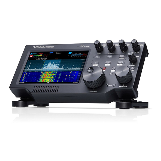
FLEX-6000 Signature Series – Maestro User Guide 3 GETTING TO KNOW YOUR MAESTRO Maestro is a self-contained hardware and software system designed to operate FLEX-6000 Signature Series radios. It can operate in a fixed mode connected to external power, or in a portable mode using internal battery power. - Page 12 FLEX-6000 Signature Series – Maestro User Guide The components of the Transceiver Controls are: 1. Slice Receiver A multi-function control for audio level, AGC Threshold, Squelch and Solo audio operation 2. Slice Receiver A multi-function control for receiver filter width and position 3.
- Page 13 FLEX-6000 Signature Series – Maestro User Guide 4. Slice Receiver B multi-function control for receiver filter width and position 5. Manual transmit (MOX) button 6. Manual tune (TUNE) button 7. Automatic Tuning Unit (ATU) button 8. Microphone level, key speed, transmitter power and TX Menu multi-function control 9.
- Page 14 FLEX-6000 Signature Series – Maestro User Guide The components of the Maestro back panel are: 1. Wired Ethernet port 2. External power port 3. Battery compartment 4. Tilt leg mounting points 5. Fixed leg mounting points 6. Physical security point 7.
-
Page 15: Setting Up Your Maestro
FLEX-6000 Signature Series – Maestro User Guide 4 SETTING UP YOUR MAESTRO To operate your Signature Series Flex 6000 transceiver with your Maestro, you must provide power, an Ethernet connection and an input device to the Maestro. Other equipment such as speakers, headphones, line level signals and push-to-talk switches are optional. -
Page 16: Input Device
FLEX-6000 Signature Series – Maestro User Guide 4.3 INPUT DEVICE A microphone or key is required to operate the transmitter in your FLEX-6000 transceiver. A straight key or paddles can be plugged into the Key port on the back panel of the Maestro. A microphone can be plugged into either the MIC 1 RJ-45 port or the MIC 2 1/8 inch TRS port. -
Page 17: Powered Speaker (Pwr Spkr) Connector
FLEX-6000 Signature Series – Maestro User Guide 4.4.2 Powered Speaker (PWR SPKR) Connector The PWR SPKR connector accepts a 1/8-inch (3.5mm) stereo (TRS) plug and provides stereo line level output for amplified PC speakers. CAUTION: Do not use a mono (TS) plug as this will short-circuit the right channel signal to ground. -
Page 18: Ptt Connector
FLEX-6000 Signature Series – Maestro User Guide 4.4.5 PTT Connector The PTT connector accepts a 1/8-inch (3.5mm) stereo (TRS) plug or mono (TS) plug. Grounding the PTT line through an external switch keys the transmitter. 4.4.6 Mic 2 Connector The MIC 2 connector accepts a 1/8-inch (3.5mm) stereo (TRS) plug and provides an unbalanced microphone input with optional push to talk input. -
Page 19: Mic 1 Connector
Although Maestro will work well with many types of microphones, it is wired for the convenient use of microphones such as the FlexRadio FMH-1-RJ45. The FHM-1-8P hand microphone supplied with the FLEX-6000 Series Radios uses an 8-pin Foster connector. This microphone may be adapted to Maestro with either the ACC-ADM817 RJ45 to 8-pin Male Foster Adapter cable or the ACC-CLV-310 RJ45 to RJ45 coiled cable replacement. -
Page 20: Vdc Coaxial Power Connector
FLEX-6000 Signature Series – Maestro User Guide 4.4.10 10-15 VDC Coaxial Power Connector The power connector accepts a 2.1mm coaxial power plug to provide 10-15 VDC at 25W. Maestro is supplied with an AC/DC power supply with a 12V output. Also included is a DC power cable with 2.1mm plug and pigtails on respective ends. - Page 21 FLEX-6000 Signature Series – Maestro User Guide Depress the latch and open the battery compartment. Remove the door. Insert a battery of suitable size. Secure the battery using the self-adhesive straps. The battery must supply 5 volts DC and should be capable of supplying a minimum of 2.0 amps through a USB type A connector.
- Page 22 FLEX-6000 Signature Series – Maestro User Guide Make the battery power connection with the USB Type A plug to the battery drain connector. Close the battery door and press the latch until it engages. Make sure the battery and the connected battery power cable fit completely inside the compartment and do not interfere with the door as it is closed.
-
Page 23: Usb Power Bank Selection
Supplemental batteries used for charging cellular phones and other electronics are plentiful and relatively inexpensive. The capacity and functionality of these batteries varies across manufacturers and models. FlexRadio has found that it is not uncommon for the advertised capacities to vary from actual measured capacities. -
Page 24: Starting/Stopping The Maestro
In summary, not all batteries will function the same in Maestro and batteries may age and fail over time. For best results, check the FlexRadio Systems Community for recommendations on batteries from FlexRadio employees and other FlexRadio owners. Good batteries should provide reliable operation over many charge/discharge cycles. - Page 25 FLEX-6000 Signature Series – Maestro User Guide Maestro supports WPA/WPA2 Wi-Fi security and can also connect to open (unsecured) Wi-Fi networks, but does not support WEP secured Wi-Fi networks. Wireless Protected Setup (WPS) is not supported. Maestro surveys the 2.4 and 5.0 GHz Wi-Fi radio frequencies for available Wi-Fi networks. This survey may take a few minutes to complete.
- Page 26 FLEX-6000 Signature Series – Maestro User Guide If Maestro is able to make a connection to the network, the Wi-Fi network setup is complete, and Maestro continues to the Select Radio screen. You can return to the Choose a Wi-Fi Network screen any time during the Maestro startup process by use of the navigation buttons in the upper left and right corners of the startup screens.
- Page 27 FLEX-6000 Signature Series – Maestro User Guide Maestro will clear any information it has stored about making a connection to that network. Subsequent Maestro startups will not connect to that Wi-Fi network until it is manually selected by the user.
-
Page 28: Network Status
FLEX-6000 Signature Series – Maestro User Guide The configuration details of the Wi-Fi and wired network interfaces are displayed. The default configuration for each interface is to use Dynamic Host Control Protocol (DHCP) to configure the interface. If a static configuration is needed, tap the Static button and enter the parameters in the IP Address, Mask and Gateway fields, then tap Apply. -
Page 29: Connecting To A Radio
FLEX-6000 Signature Series – Maestro User Guide 5 CONNECTING TO A RADIO After Maestro starts, a screen is displayed showing radios found on your local network. Maestro locates these radios using a network broadcast protocol that is limited to the local subnet that Maestro is connected to. - Page 30 FLEX-6000 Signature Series – Maestro User Guide To connect to a radio that is in use by another client, select the radio by tapping it. A Disconnect User button will appear to the right of the Connect button. Tap this button to disconnect the other client.
-
Page 31: How To Select Maestro And Radio Software
FLEX-6000 Signature Series – Maestro User Guide 6 HOW TO SELECT MAESTRO AND RADIO SOFTWARE After a radio is selected, Maestro will display the Select a Version screen, and a list of available versions of Maestro software and radio firmware. -
Page 32: Licensing Smartsdr Version 2
6.2 LICENSING SMARTSDR VERSION 2 Version 2 of SmartSDR for Windows is licensed software. FlexRadio Systems makes the Version 2 software available under license to owners and users of FlexRadio Systems 6000 Series radios. Most 6000 Series owners will need to purchase a license as part of the version 2 installation process. - Page 33 FLEX-6000 Signature Series – Maestro User Guide Note: Do not use this URL in a mobile device browser. The URL may be corrupted leading to errors in the licensing process that may require technical support to correct. Use the URL in a desktop computer browser.
-
Page 34: Smartlink
FLEX-6000 Signature Series – Maestro User Guide 7 SMARTLINK 7.1 SMARTLINK OVERVIEW Use SmartLink™ with a Maestro connected to the Internet to operate your Flex 6000 Series radio at a remote location. SmartLink provides authenticated, secure access to the radio over the Internet at effective data transfer speeds. -
Page 35: Smartlink Setup
FLEX-6000 Signature Series – Maestro User Guide 7.2 SMARTLINK SETUP 7.2.1 Create a SmartLink Account SmartLink requires an online user account to store the SmartLink user credentials and connection information about the radios users are authorized to use. To create your SmartLink account or log into an existing account, start Maestro, go to the Select Radio screen and tap the Log In button near the bottom right of the screen. - Page 36 FLEX-6000 Signature Series – Maestro User Guide The following screen will appear. If you do not have a SmartLink account, tap Sign Up in the SmartLink Login screen to create an account using either an email address and password of your choice, or the credentials of an existing Google or Facebook account.
- Page 37 FLEX-6000 Signature Series – Maestro User Guide If you already have a SmartLink account, tap Log In in the SmartLink Login screen and then enter either your email address and password, or tap the Facebook or Google button to log in using credentials from those systems.
-
Page 38: Register The Radio In Smartlink
FLEX-6000 Signature Series – Maestro User Guide 7.2.2 Register the Radio in SmartLink The next step is to register your radio in your SmartLink account. At the Select Radio screen, tap the radio to select it. Connect and SmartLink Setup buttons will appear at the bottom of the screen. Tap the SmartLink Setup button. - Page 39 FLEX-6000 Signature Series – Maestro User Guide After a brief period to establish a secure connection, a prompt to key the radio will be shown. Use a Hand Mic, CW Paddles, or an RCA PTT input to key the radio. This cannot be done via the Maestro MOX button or any remote keying input.
-
Page 40: Test The Radio In Smartlink
FLEX-6000 Signature Series – Maestro User Guide When the radio is registered, the screen will update to indicate the registered status as shown below. The final configuration step is to map communication ports in the radio to the outside world. Open the Network Settings pane as shown above and select Automatic mode. -
Page 41: Using Smartlink
FLEX-6000 Signature Series – Maestro User Guide 7.3 USING SMARTLINK Use SmartLink with a Maestro connected to the Internet to operate your Flex 6000 Series radio at a remote location. SmartLink provides authenticated, secure access to the radio over the Internet at effective data transfer speeds. - Page 42 FLEX-6000 Signature Series – Maestro User Guide When the log in is complete, return to the SmartSDR start screen, which will now look similar to the following: Radios available through SmartLink are shown in the list with the logo. Page...
- Page 43 FLEX-6000 Signature Series – Maestro User Guide Tap the desired radio to select it. Info, Connect and SmartLink Setup buttons will appear at the bottom of the screen. Tap the Connect button to connect to the radio. The Select a Version screen will appear.
- Page 44 FLEX-6000 Signature Series – Maestro User Guide If the data rate from the radio to Maestro is higher than can be supported by the radio’s Internet connection use the Low BW Connect button to start the radio using panadapter settings that minimize the Internet data transfer rate.
-
Page 45: Maestro Overview
FLEX-6000 Signature Series – Maestro User Guide 8 MAESTRO OVERVIEW 8.1 THEORY OF OPERATION Maestro is a hardware and software system designed to operate FLEX-6000 Signature Series radios. FLEX-6000 radios perform wide-band sampling of the RF spectrum. How is wide-band sampling different from other radios? In superheterodyne (also called “superhet”... -
Page 46: Panadapter
FLEX-6000 Signature Series – Maestro User Guide audio, each Slice Receiver shares the same base performance as the other Slice Receivers. For the operator, this means that access to two receivers with the same top performance may be used interchangeably without concern for differing performance characteristics of each receiver often found in superheterodyne receivers. -
Page 47: Panafall
FLEX-6000 Signature Series – Maestro User Guide 8.2.5 Panafall The Panafall display is simply a Panadapter and a Waterfall that are joined such that the horizontal axis has the same frequency location. In this way, the Panadapter portion of the display will show the current state of the spectrum and the Waterfall portion will show a historical perspective. -
Page 48: How To Operate A Slice Receiver
FLEX-6000 Signature Series – Maestro User Guide 9 HOW TO OPERATE A SLICE RECEIVER 9.1 HOW TO CREATE AND DELETE A SLICE RECEIVER Maestro can control two Slice Receivers labeled A and B. The first two columns of knobs and buttons on the Maestro front panel control the A Slice, the second two columns control the B Slice. -
Page 49: Making A Slice Receiver Active
FLEX-6000 Signature Series – Maestro User Guide faster. The size of the steps, in Hertz, is controlled by the A and B Step buttons. See section 33.2, Slice Receiver Tuning Knobs and Buttons for full details. Drag Tuning: Drag Tuning is one of the more common tuning methods. By touching the Receive Filter... -
Page 50: How To Change The Demodulation Mode
FLEX-6000 Signature Series – Maestro User Guide 9.4 HOW TO CHANGE THE DEMODULATION MODE When a Slice Receiver is active, the Slice Receiver Flag shows the mode and receive filter width in use. To change the mode, tap the frequency display or depress the slice receiver’s tuning knob for two... -
Page 51: Recording And Playback Of Slice Receiver Audio
FLEX-6000 Signature Series – Maestro User Guide parameter, relative to the Slice Receiver’s tuned frequency as the filter is adjusted. Information about the Receive Filter’s width and the knob mode is shown in the Slice Flag’s Annunciator area. A short press of the inner knob cycles the RX filter through a series of preset filter configurations that are determined by the selected mode. -
Page 52: How To Operate The Panadapter / Waterfall
FLEX-6000 Signature Series – Maestro User Guide 10 HOW TO OPERATE THE PANADAPTER / WATERFALL 10.1 HOW TO CREATE / DELETE A PANADAPTER / WATERFALL Maestro runs with a minimum of one and a maximum of two Panadapters. To add the second Panadapter, tap the upward pointing arrow at the bottom center of the display. - Page 53 FLEX-6000 Signature Series – Maestro User Guide Tapping the Panadapter reveals plus and minus magnifying glass buttons located in the upper left corner of the Panadapter. Tap these buttons to zoom the Panadapter in or out. Zooming out (-) will double the bandwidth presented in the Panadapter while zooming in (+) will halve the bandwidth.
-
Page 54: How To Change The Signal Magnitude Scale Of A Panadapter
FLEX-6000 Signature Series – Maestro User Guide 10.5 HOW TO CHANGE THE SIGNAL MAGNITUDE SCALE OF A PANADAPTER The maximum and minimum amplitude displayed in each Panadapter may be adjusted. Tapping the or down arrows displayed along the left edge of the Panadapter increases or decreases, respectively, in 10 dB increments, the maximum amplitude displayed. -
Page 55: Noise Mitigation
FLEX-6000 Signature Series – Maestro User Guide 11 NOISE MITIGATION In order to properly utilize the DSP noise reduction features of the Flex 6000 Series radios, it is important to understand the type of noise causing interference. There is no single solution for noise mitigation since different types of noise require different algorithms. -
Page 56: How To Configure Noise Mitigation
FLEX-6000 Signature Series – Maestro User Guide 12 HOW TO CONFIGURE NOISE MITIGATION The FLEX-6000 Series radios have a number of digital-signal-processing functions that enhance reception in noisy environments. 12.1 AGC THRESHOLD Automatic Gain Control (AGC) is a feature which automatically adjusts the Slice Receiver’s audio gain (volume) based on the strength of signals in the receiver’s passband filter. -
Page 57: Dsp Noise Mitigation Features
FLEX-6000 Signature Series – Maestro User Guide Operating with AGC turned OFF may be desired by operators who want to avoid having a strong signal drive a weak nearby signal into the noise floor resulting from AGC audio attenuation. Digital mode operation may benefit from this configuration. -
Page 58: Slice Specific Noise Blanker (Nb)
FLEX-6000 Signature Series – Maestro User Guide This unique architecture allows pulse removal with far less distortion than many traditional noise blankers. Given the wideband nature of this feature, the threshold slider controls an entire Panadapter, which may have several Slice Receivers attached to it. This means that the WNB can positively impact not only the audio of Slice Receivers, but also the panafall visual display. - Page 59 FLEX-6000 Signature Series – Maestro User Guide noise is changing rapidly or dramatically. The most aggressive settings of Noise Reduction increase the signal to noise ratio but will tend to “color” the signal. The slider should be set for the optimal tradeoff between signal to noise ratio and minimal distortion of the desired signal.
-
Page 60: How To Use Tracking Notch Filters
FLEX-6000 Signature Series – Maestro User Guide 13 HOW TO USE TRACKING NOTCH FILTERS 13.1 TRACKING NOTCH FILTER THEORY With the notch filters found on most receivers, the notch removes an audio frequency after the AGC. When you hear a carrier in the middle of a sideband transmission, you can enable the notch and adjust it to remove the objectionable carrier. - Page 61 FLEX-6000 Signature Series – Maestro User Guide A TNF will be shown by a greenish vertical line with diagonal yellow stripes. The TNF can be moved by dragging it (just like a slice), and the width can be adjusted by sliding your finger up and down.
-
Page 62: Turning All Tracking Notch Filters On Or Off
FLEX-6000 Signature Series – Maestro User Guide 13.3 TURNING ALL TRACKING NOTCH FILTERS ON OR OFF To disable all TNFs at the same time, touch on the TNF button in the top-left corner of the Slice menu. To remove all TNFs, tap and hold the TNF button. The Remove All TNFs option will appear as shown below. -
Page 63: Automatic Notch Filter (Anf)
FLEX-6000 Signature Series – Maestro User Guide 13.4 AUTOMATIC NOTCH FILTER (ANF) The Automatic Notch Filter automatically applies a Tracking Notch Filter, as described above, to remove constant tones such as carriers and heterodynes from the received audio passband. These filters can be applied to each Slice Receiver as needed. -
Page 64: How To Use Profiles
FLEX-6000 Signature Series – Maestro User Guide 14 HOW TO USE PROFILES Profiles allow the user to name and save the state of the radio and recall it later. Profiles can even be exported and restored on another FLEX-6000 Series radio. This facilitates convenient backup of radio configurations and also helps IT managers of DXpeditions or contest super-stations test configurations and then install or restore them at a site. -
Page 65: Transmit Profiles
FLEX-6000 Signature Series – Maestro User Guide • Change Slice A to SAM (This loads the default linked MIC profile Default) • Load Default PR781 Mic profile. (This Mic profile is now linked to the AM/SAM mode group) • Change Slice A to LSB or USB. (This loads the Default FHM-1 Mic profile) •... -
Page 66: Global Profiles
FLEX-6000 Signature Series – Maestro User Guide Each Transmit profile saves a set of power settings, one setting for each band. To save power settings for each band, select the Transmit profile from the drop-down menu, then tune to each band and adjust the power settings. -
Page 67: Loading Profiles
FLEX-6000 Signature Series – Maestro User Guide appropriate for the profile you wish to save or delete. This will bring up one of the following Profiles control panels: To save a new profile, tap the New Global Profile, New TX Profile or New MIC Profile text box. A keyboard will appear. -
Page 68: Default Profiles
FLEX-6000 Signature Series – Maestro User Guide Note: You can load profiles created by different FLEX-6000 models without any adverse interactions. 14.6 DEFAULT PROFILES A number of default profiles are included in the radio software. These profiles provide a basic level operation for the radio and are listed in the illustrations in section 14.4, Saving and Deleting Profiles... - Page 69 FLEX-6000 Signature Series – Maestro User Guide Persistence remembers a large number of settings as shown in the following table: Radio PTT Timeout Show mic meter in receive TX1/2/3/Acc enabled and delay Show transmit signals in Waterfall TXREQ enabled and polarity (RCA & ACC)
- Page 70 FLEX-6000 Signature Series – Maestro User Guide Global Profile Fields PANADAPTER SLICE Global Center Frequency CWX Macro 1 Frequency RX EQ Enable XVTR Frequency CWX Macro 2 XVTR Frequency RX EQ Levels (all frequencies) XVTR Key CWX Macro 3 XVTR Key...
- Page 71 FLEX-6000 Signature Series – Maestro User Guide TX Profile Fields MIC Profile Fields Interlock Power TX Filter Low TX Delay Hardware ALC Enabled TX Filter High PTT Timeout Tune Level Mic Selection PTT Inhibit Power Level Mic Level ACC TX Request Enable XVTR Tune Level...
-
Page 72: How To Operate Maestro Audio
FLEX-6000 Signature Series – Maestro User Guide 15 HOW TO OPERATE MAESTRO AUDIO Maestro can be operationally “decoupled” from the radio hardware by playing Slice Receiver audio through the Maestro speaker (or another attached playback device) and using a connected microphone or other audio input device to make phone QSOs. -
Page 73: Configuring The Audio Output Devices
For this reason, FlexRadio recommends using wired networks for CW as there tend to be less issues that require troubleshooting on wired networks. Maestro will always attempt to compensate for any jitter or latency caused by any kind of network, but the mechanism for compensation is to add latency to ensure a steady stream of CW at the radio transmitter. -
Page 74: Network Health Indicator
FLEX-6000 Signature Series – Maestro User Guide 15.6.1 Network Health Indicator The network health indicator provides a quick way to determine if your network connection is performing well enough to properly operate your radio for both remote and local modes of operation. -
Page 75: Network Diagnostics
FLEX-6000 Signature Series – Maestro User Guide 15.6.2 Network Diagnostics When LAN issues occur with Maestro, it is useful to have additional details to aid in diagnosing the problem. A Network Diagnostics feature provides this information. To access this information, open the Network tab in the Main Menu. -
Page 76: How To Operate Cw Mode
FLEX-6000 Signature Series – Maestro User Guide 16 HOW TO OPERATE CW MODE To use Maestro in CW mode, select CW in the Slice Receiver Menu. This shows the narrower CW receive filter presets in the Slice Receiver Menu and brings up the CW specific controls in the TX Menu. -
Page 77: How To Operate Cw In Split Mode
FLEX-6000 Signature Series – Maestro User Guide 16.1 HOW TO OPERATE CW IN SPLIT MODE Many DXpeditions prefer to operate in split mode, in which they transmit on one frequency, but listen on another, up or down a few kilohertz. In order to do this with Maestro, the A Slice must be set to the DX station’s transmitting frequency, and the B Slice must be inactive. -
Page 78: Cw Transmitting
FLEX-6000 Signature Series – Maestro User Guide 16.2 CW TRANSMITTING In order to transmit in CW mode using the keyer built-into the FLEX-6000 radio, you will need either a straight key or an iambic paddle. Refer to the FLEX-6000 Hardware Reference Manual and to section 4.4.1, Straight Key or Paddles (KEY) of this document for wiring instructions. - Page 79 FLEX-6000 Signature Series – Maestro User Guide TX Menu, CW Mode To use a straight key, disable the Iambic control and enable Dot/Dash Swap in the Phone/CW control panel in the Maestro Main Menu. Connect the straight key to the tip and sleeve of a 1/8 inch TRS plug and connect it to the Key input on the back panel of the Maestro.
-
Page 80: Using The Built-In Keyer
FLEX-6000 Signature Series – Maestro User Guide 16.3 USING THE BUILT-IN KEYER Maestro has a built-in iambic keyer that can be used either as iambic “A” or iambic “B”. Controls for the keyer are found on the Phone/CW tab of the Maestro Main Menu. See section 30.8, Phone/CW Tab for details about these controls. -
Page 81: How To Connect An External Keyer Using The Fsk/Key Input On The Accessory Connector
FLEX-6000 Signature Series – Maestro User Guide 16.5 HOW TO CONNECT AN EXTERNAL KEYER USING THE FSK/KEY INPUT ON THE ACCESSORY CONNECTOR In CW mode, the FSK/Key input on the FLEX-6000 rear panel accessory connector (pin 4) can be used as a straight key input. -
Page 82: How To Operate Single Sideband Mode (Ssb)
FLEX-6000 Signature Series – Maestro User Guide 17 HOW TO OPERATE SINGLE SIDEBAND MODE (SSB) To use the Maestro in SSB mode, select either USB or LSB in the Slice Receiver Menu. This brings up the SSB receive filter presets and shows the SSB specific controls in the transmit panel. Conventional USB or LSB settings are automatically selected for each band when the band selection panel is used. - Page 83 FLEX-6000 Signature Series – Maestro User Guide button. The B Slice will become active, its frequency will be set to a value 5 KHz higher than the A Slice Receiver’s frequency and the transmitter control will move to the B Slice. Your Panadapter...
-
Page 84: How To Configure The Audio Controls For Phone Modes
FLEX-6000 Signature Series – Maestro User Guide 17.4 HOW TO CONFIGURE THE AUDIO CONTROLS FOR PHONE MODES Connect a suitable microphone to the RJ45 MIC1 connector or the 1/8 inch TRS MIC2 connector on the back panel of the Maestro. Press the Maestro TX Menu button to bring up the TX Menu, then select the appropriate microphone from the microphone list at the left side of the menu. -
Page 85: Operating The Speech Processor
FLEX-6000 Signature Series – Maestro User Guide indicate the input level range. Signals up to -10 dB are shown in green. Signals levels between -10 and 0 dB are shown in yellow. Any signal level greater than 0 dB is shown in red. -
Page 86: How To Configure Vox
FLEX-6000 Signature Series – Maestro User Guide The Transmit Equalizer control panel is found on the Transmit tab of the Main Menu as shown above. When enabled, the graphic equalizer can be optimized for different microphones and operating styles such as DX, contesting and SSB. The sliders provide a +/- 10 dB adjustment range over eight octaves. -
Page 87: How To Configure The Downward Expander (Dexp)
FLEX-6000 Signature Series – Maestro User Guide Note: The MON feature allows for monitoring of the processed audio prior to the final brick wall filtering and ALC limiting, compression and equalization, allowing the operator to listen to the transmitted audio in “real time” with minimal latency or delay. However, since the monitor... -
Page 88: Recommended Audio Adjustment Steps For Phone Modes
FLEX-6000 Signature Series – Maestro User Guide • Press MOX or press a PTT to enable the transmitter. • Tap the RECORD icon (red dot) on the control panel. It will flash when recording. • Talk normally into the microphone. -
Page 89: How To Operate Am And Sam Modes
FLEX-6000 Signature Series – Maestro User Guide 18 HOW TO OPERATE AM AND SAM MODES To use the Maestro in Amplitude Modulation (AM) or Synchronous AM (SAM) mode, select either AM or SAM in the Slice Receiver Menu. In selective fading conditions SAM mode, may provide better detection of AM signals. -
Page 90: How To Operate Fm Mode
FLEX-6000 Signature Series – Maestro User Guide 19 HOW TO OPERATE FM MODE To use the Maestro in Frequency Modulation (FM), Narrow FM (NFM) mode or Digital FM (DFM) mode, select either FM, NFM or DFM in the Slice Receiver Menu. -
Page 91: Memory Channels
FLEX-6000 Signature Series – Maestro User Guide 19.2 MEMORY CHANNELS FM settings can be stored in the Memory form accessible on the Memory tab of the Main Menu. The memory form, as shown below, stores the memory frequency along with other settings such as the mode, CTCSS tone, etc. - Page 92 FLEX-6000 Signature Series – Maestro User Guide • Mode - The Modulation/Demodulation mode for the Slice (e.g. USB, CW, FM, etc.). Initially set to the Active Slice mode. • Step – The frequency step size in Hertz, associated with this setting.
-
Page 93: How To Operate Diversity Reception (Flex-6600(M) And 6700 Only)
FLEX-6000 Signature Series – Maestro User Guide 20 HOW TO OPERATE DIVERSITY RECEPTION (FLEX-6600(M) AND 6700 ONLY) Diversity reception is a powerful method for improving the readability of a signal by using two or more communication channels with different characteristics. Diversity reception is very useful for aiding reception in weak and fading (QSB) signal conditions. - Page 94 FLEX-6000 Signature Series – Maestro User Guide To enable diversity reception, tap the DIV button in the Slice Receiver Menu as shown below. This will create a diversity slave Slice locked to the same frequency as the master Slice of the diversity pair.
- Page 95 FLEX-6000 Signature Series – Maestro User Guide Maestro automatically sets the Slice audio faders to place the two antennas in the left and right ears respectively. Your brain does the rest. Remember that the sound will be very different from normal reception since you are literally listening in “stereo”...
-
Page 96: How To Operate The Atu
FLEX-6000 Signature Series – Maestro User Guide 21 HOW TO OPERATE THE ATU The antenna tuning unit (ATU) is a device in the RF signal path that improves power transfer from the transmitter to the antenna by transforming the apparent antenna impedance seen by the transmitter to a value compatible with the transceiver’s power amplifier (PA). -
Page 97: Manual Mode
FLEX-6000 Signature Series – Maestro User Guide 21.3 MANUAL MODE To operate the ATU in Manual mode, make sure the ATU MEM button in the TX Menu is unlit by tapping it. ATU memories are enabled by default. Tune the transmitter to the desired frequency. Press the ATU button to initiate an ATU tuning operation. - Page 98 FLEX-6000 Signature Series – Maestro User Guide Regardless of the outcome, when in Memory mode, the ATU will update its stored settings so that they can be reapplied when the transmitter is tuned to the frequency again. For high Q antennas that have a very narrow low SWR range, ATU memories may be saved every 10 kHz for a very granular ATU memory profile for that particular antenna.
-
Page 99: How To Configure Antennas
FLEX-6000 Signature Series – Maestro User Guide 22 HOW TO CONFIGURE ANTENNAS 22.1 GETTING STARTED When Maestro starts, it loads a single Panadapter and Slice Receiver with Antenna 1 (ANT1) selected by default. Transmit and receive operations are then functional on ANT1 with no further setup or adjustment required. -
Page 100: Using A Common Receive Antenna With Separate Transmit Antennas
FLEX-6000 Signature Series – Maestro User Guide 22.4 USING A COMMON RECEIVE ANTENNA WITH SEPARATE TRANSMIT ANTENNAS The image above illustrates two Slice Receivers using a single receive antenna (ANT1) but using separate transmit antennas on ANT1 and ANT2 respectively. Slice A and B both have ANT1 selected. -
Page 101: Using Two Transceive Antennas On The Flex-6700
FLEX-6000 Signature Series – Maestro User Guide 22.5 USING TWO TRANSCEIVE ANTENNAS ON THE FLEX-6700 In the image above, Slice A is set to receive and transmit on ANT1. Slice B is set to receive and transmit on ANT2. Slice B is selected as the active transmit frequency of 7.033 MHz on ANT2 as indicated by the red TX button. -
Page 102: Using A Dedicated Receive Antenna
FLEX-6000 Signature Series – Maestro User Guide 22.6 USING A DEDICATED RECEIVE ANTENNA In the image above, Slice A has a dedicated receive antenna on RX A and is transmitting on ANT1. The FLEX-6700/6700R models have the option of using separate receive antennas on RX A and RX B respectively. -
Page 103: Antenna Selection For Transverter Operation
FLEX-6000 Signature Series – Maestro User Guide In the image above, a FLEX-6700 is configured so that the Slice A receive antenna is set to RX A and the Slice B antenna to RX B. ANT1 is selected as the transmit antenna for Slice A and ANT2 for Slice B. -
Page 104: Using The Receiver Rf Gain/Preamplifiers
FLEX-6000 Signature Series – Maestro User Guide 22.9 USING THE RECEIVER RF GAIN/PREAMPLIFIERS Each Spectral Capture Unit (SCU) in the FLEX-6000 includes a preamplifier with adjustable gain. The RF gain selector is located near the top of the ANT menu. -
Page 105: Setting The Rf Gain/Preamplifiers
FLEX-6000 Signature Series – Maestro User Guide 22.10 SETTING THE RF GAIN/PREAMPLIFIERS Each Spectral Capture Unit in a FLEX-6000 receiver includes an RF preamplifier with adjustable gain. The RF gain selector is in the ANT menu on the left side of the screen. The gain range is selectable in 10 dB steps from -10 dB to +40 dB on the FLEX-6700, 8 dB steps from -8 dB to +32 dB on the FLEX- 6400 and FLEX-6600, -10 dB to +20 dB on the FLEX-6500 and 0dB to +20dB on the FLEX-6300. -
Page 106: Antenna Configuration Basic Terms And Rules
FLEX-6000 Signature Series – Maestro User Guide 22.11 ANTENNA CONFIGURATION BASIC TERMS AND RULES For more advanced antenna configurations, it is helpful to define terms used to describe the FLEX- 6000 Signature Series architecture and the rules associated with its configuration. - Page 107 FLEX-6000 Signature Series – Maestro User Guide • The XVTR input/output port may be used on the FLEX-6300, FLEX-6500 and FLEX-6700 as another receive-only input or may be used as a transverter transmit or common receive port. RX A and/or RX B on may be used for split transmit receive operation when selected as the receive antenna and XVTR as the transmit antenna.
-
Page 108: Displaying Spots In Smartsdr For Maestro
FLEX-6000 Signature Series – Maestro User Guide 23 DISPLAYING SPOTS IN SMARTSDR FOR MAESTRO SmartSDR v2.3 for Maestro introduced a feature that allows spots, supplied by third party programs, to be displayed directly in the Panadapter window. Some of these programs include N1MM, FRStack, Slicemaster, DXLabs, and Logger32. - Page 109 FLEX-6000 Signature Series – Maestro User Guide When a spot is tapped, the Active Slice will automatically tune to the spot frequency. When there are many spots in a single area, they collapse into a number value. In the image below, the “+3” is such a collection of spots.
- Page 110 FLEX-6000 Signature Series – Maestro User Guide The Spot settings tab can be reached by going to Menu → Spots. The Spots button enables or disables the Spots feature. The Levels slider changes the depth of the displayed spots before collapsing them into a list of spots.
-
Page 111: How To Configure Transverters
FLEX-6000 Signature Series – Maestro User Guide 24 HOW TO CONFIGURE TRANSVERTERS To configure transverters, open the transverter control panel on the XVTR tab of the Maestro Main Menu. The transverter setup panel should look like this: To add a transverter band, tap the Add button. A new transverter band tab will appear which has blanks that need to be filled in with information about your transverter. - Page 112 FLEX-6000 Signature Series – Maestro User Guide RX Only: Enable this if you do not want to transmit through your transverter. It will lock-out the transmit capabilities in Maestro. IF Freq (MHz): the IF frequency that corresponds to the RF frequency previously entered. Currently Maestro only understands high-side injection, so the IF frequency must be below the LO frequency of your transverter.
-
Page 113: Using A Transverter
FLEX-6000 Signature Series – Maestro User Guide 24.1 USING A TRANSVERTER There are two ways to tune to a transverter. The first way is to use the band select panel in the Slice Receiver Menu. Open the control panel and then tap the XVTR button at the lower right of the band selection buttons. -
Page 114: Multiple Copies Of A Band
FLEX-6000 Signature Series – Maestro User Guide The second way to select a transverter band is to directly enter the frequency of the desired operation into the Slice Receiver. For example, entering “1296.” (don’t forget the decimal point to tell Maestro that we want to go to 1296MHz) will move the Panadapter and Slice to 1296MHz. -
Page 115: Transmitting On A Transverter
FLEX-6000 Signature Series – Maestro User Guide 24.4 TRANSMITTING ON A TRANSVERTER When transmissions occur on the transverter, the radio will reconfigure internal relays to connect the exciter in the FLEX-6000 to the XVTR port on the radio. If a split IF is in use, the RXA or RXB port may continue to be used for receiving provided that your transverter continues to provide receive RF (check with transverter manufacturer). -
Page 116: Using The Flexradio Power Genius Xl Amplifier
Full details can be found in the Power Genius XL User Guide, available from the FlexRadio Systems website. The only configuration change needed to operate the Power Genius XL amplifier from SmartSDR for Maestro is to configure the correct transmit time delay. - Page 117 FLEX-6000 Signature Series – Maestro User Guide When the button is dimmed and reads “AMP Standby”, the amplifier is connected to the radio but is in standby mode. If a signal is transmitted, the amplifier will not amplify it. Tap on the button to change the amplifier state to “Operate”.
-
Page 118: How To Connect An External Amplifier
FLEX-6000 Signature Series – Maestro User Guide 26 HOW TO CONNECT AN EXTERNAL AMPLIFIER The FLEX-6000 has hardware interfaces for connecting an external power amplifier. There are four PTT outputs on the FLEX-6700 and FLEX-6500 and two outputs on the FLEX-6300, each with independently configurable time delays, a transmit hold-off input for amplifiers that have QSK hold- off outputs, and a standard zero to negative four Volt hardware ALC input. -
Page 119: Usb Cables
In some cases, data flow is bidirectional with a wide selection of speeds and signaling levels. FlexRadio carries two FTDI cables that can be used to interface with many devices: •... -
Page 120: Cable Management
FLEX-6000 Signature Series – Maestro User Guide 27.2 CABLE MANAGEMENT USB Cables are managed in the USB Cables tab in the Maestro Main Menu: Using the USB Cables window, cables can be selected, activated and deactivated, modified, logged and removed. The information in the window includes: •... -
Page 121: Cat Cables
FLEX-6000 Signature Series – Maestro User Guide 27.2.1 CAT Cables CAT cables are serial data communication cables on which a small subset of the CAT command set is implemented. Most of the functions implemented on these cables are frequency reporting functions. - Page 122 FLEX-6000 Signature Series – Maestro User Guide The CAT commands supported on CAT cables are: • FA and ZZFA: Report the source frequency, Get/Read Only • FB and ZZFB: Report the source frequency, Get/Read Only. FA and FB report the same information.
-
Page 123: Bit Cables
FLEX-6000 Signature Series – Maestro User Guide 27.2.2 BIT Cables BIT cables provide a means to map the tuned frequency of the radio to a set of individual signals/wires at the end of the cable. These cables are designed to control external devices when the radio is tuned to specific bands or frequency ranges, and for external keying or sequencing that is triggered when the transmitter becomes active. -
Page 124: Bcd Cables
FLEX-6000 Signature Series – Maestro User Guide 27.2.3 BCD Cables BCD cables provide a means to map the tuned frequency of the radio to a 4 or 5 bit Binary Coded Decimal output representing specific bands. The BCD signal that appears on the cable is configured by use of the controls in the USB Cables menu: •... - Page 125 FLEX-6000 Signature Series – Maestro User Guide BCD Output Band Bit 4 Bit 3 Bit 2 Bit 1 Bit 0 VHF VBCD Output Band Bit 4 Bit 3 Bit 2 Bit 1 Bit 0 1296 2304 3456 5760 10368 24048...
-
Page 126: Ldpa Cables
FLEX-6000 Signature Series – Maestro User Guide HF + VHF Output Band Bit 4 Bit 3 Bit 2 Bit 1 Bit 0 1296 2304 3456 5760 10368 24048 47088 27.2.4 LDPA Cables Control cables for Low Drive Power Amplifiers for the 2 and 4 meter bands produced by Down East Microwave Inc. -
Page 127: How To Operate In Digital Modes
FLEX-6000 Signature Series – Maestro User Guide 28 HOW TO OPERATE IN DIGITAL MODES Digital modes such as FT8, JT65 and PSK31 are implemented in third party programs that must run in a computer separate from Maestro. The recommended configuration uses DAX and CAT on a PC to connect the digital mode program to the FLEX-6000. -
Page 128: Rtty Mode
FLEX-6000 Signature Series – Maestro User Guide 28.2 RTTY MODE RTTY mode is a variant of DIGL mode, optimized to facilitate tuning and reporting of a RTTY Mark frequency via CAT or the FlexLib API. In RTTY mode two controls appear in the Slice Receiver Menu. -
Page 129: Digi Mode Audio Offsets
FLEX-6000 Signature Series – Maestro User Guide 28.3 DIGI MODE AUDIO OFFSETS When operating the radio in DIGU or DIGL mode a receive filter Offset control is available in the Slice Receiver Menu. This control allows the operator to set the audio offset in Hertz of the center of the receiver’s bandpass preset filters. -
Page 130: How To Operate In Full Duplex (Fdx) Mode
FLEX-6000 Signature Series – Maestro User Guide 29 HOW TO OPERATE IN FULL DUPLEX (FDX) MODE All FLEX-6000 Signature Series Transceivers are inherently capable of full duplex operation. In normal simplex operation, all Slice Receivers are muted when transmitting. When Full Duplex (FDX) is enabled, the transmitting Slice Receiver is muted along with all other Slice Receivers on the same antenna. -
Page 131: Fdx Capabilities By Radio Model
FLEX-6000 Signature Series – Maestro User Guide 29.3 FDX CAPABILITIES BY RADIO MODEL The capabilities and rules for FDX operation vary by model as defined by its respective hardware capabilities. Specifics for each model are as follows. 29.3.1 FLEX-6600(M) and FLEX-6700 SO2R Operation The FLEX-6600(M) and FLEX-6700 incorporate two independent, full performance Spectral Capture Units (SCUs), each with its own band pass filter pre-selectors. -
Page 132: Flex-6300 And Flex-6500 Full Duplex
FLEX-6000 Signature Series – Maestro User Guide The image below illustrates an example SO2R configuration using the FLEX-6700. 29.3.2 FLEX-6300 and FLEX-6500 Full Duplex Both the FLEX-6300 and FLEX-6500 models are enabled for full duplex operation using XVTR as a receive-only port so long as at least 70 dB of port to port isolation is provided for a 100W station. -
Page 133: Preselection Band Filter Block
FLEX-6000 Signature Series – Maestro User Guide The Spectral Capture Units (SCU) in the FLEX-6000 transceivers contain three primary component blocks: • Preselection band filters (except in FLEX-6300) • A preamplifier / attenuator • A high-performance analog to digital converter (ADC) also known as a digitizer Each of these blocks plays a role in receiver performance and must be considered when planning full duplex operation. -
Page 134: High-Performance Analog To Digital Converter Block (Adc)
FlexRadio Systems assumes no responsibility for damage incurred from high signal levels entering the receiver. -
Page 135: Main Menu
FLEX-6000 Signature Series – Maestro User Guide 30 MAIN MENU 30.1 INTRODUCTION A button that opens the Maestro Main Menu is located at the top center of the Maestro display. Tapping this button opens the Main Menu. A list of menu tabs appears down the left side of the menu. -
Page 136: Radio Tab
FLEX-6000 Signature Series – Maestro User Guide 30.3 RADIO TAB Located in the Radio tab is basic information about the selected radio. The tab contains the radio Hardware Version and installed Options of the radio. The Region indicator displays the country for which the radio’s transmit capabilities are based. - Page 137 FLEX-6000 Signature Series – Maestro User Guide 1. Select a signal of known frequency, with strength greater than S6. In the US, WWV is a good choice. 2. Enter the known frequency in the Calibration Frequency field 3. Click Start The radio will tune to the signal and compare its tuned frequency to the declared frequency.
-
Page 138: Function F1-F6 Tab
FLEX-6000 Signature Series – Maestro User Guide 30.4 FUNCTION F1-F6 TAB The Function tab contains controls used to assign functions to the six front panel function buttons. To assign a function to a function button, tap the appropriate drop-down menu box, move the selections up and down with a finger swipe, then tap on the desired function. -
Page 139: Network Tab
FLEX-6000 Signature Series – Maestro User Guide • Set Mode: Change the Active Slice Receiver mode to a new value • Send CW: Send a short message in CW mode • Split: Invoke split operation on the Active Slice Receiver •... - Page 140 FLEX-6000 Signature Series – Maestro User Guide Pressing the Advanced button reveals controls that allow the user to assign a fixed IP address to the radio. Press the Static button then tap the IP Address field to bring up a keyboard. Enter the desired IP address, sub-net mask and gateway address, then press Apply.
- Page 141 FLEX-6000 Signature Series – Maestro User Guide Tapping the Reset Stats button resets the network performance statistics shown in the next line. The network statistics show the number of lost network data packets from the radio to Maestro. Loss of packet may cause interruptions in the receiver audio stream. On a wired LAN, packet losses should be very small, if any.
-
Page 142: Audio Tab
FLEX-6000 Signature Series – Maestro User Guide 30.6 AUDIO TAB The Audio tab provides a number of controls for audio output. The Main Audio Out button controls Maestro’s access to audio from the radio. When enabled, audio is sent to Maestro for reproduction in speakers or headphones. When disabled, audio is kept at the radio where it may be sent to attached speakers or headphones. -
Page 143: Transmit Tab
FLEX-6000 Signature Series – Maestro User Guide The Radio section sliders and buttons control the audio volume at the radio when the Main Audio Out control is set to Radio. When it is set to Maestro, these controls have no effect. - Page 144 FLEX-6000 Signature Series – Maestro User Guide In the General section, the Tune Power control sets a limit on the transmitter power level when the TUNE button is pressed on the front panel. Tapping this field opens a keyboard so the value can be changed.
-
Page 145: Phone/Cw Tab
FLEX-6000 Signature Series – Maestro User Guide 30.8 PHONE/CW TAB The Phone/CW tab provides a number of controls for managing the microphone and CW key interfaces. In the Microphone section, the Maestro BIAS button enables the +5 VDC microphone bias voltage on the Maestro MIC 2 connector. - Page 146 FLEX-6000 Signature Series – Maestro User Guide A paddle set can be used as a “bug” by disabling the Iambic control. In this mode, one paddle will key the transmitter continuously, the other will create a string of dots. In both of these configurations, the Swap control reverses the paddle assignments.
-
Page 147: Xvtr Tab
FLEX-6000 Signature Series – Maestro User Guide o Bandwidth from 400 to 1000 Hz: Level 2 o Bandwidth from 1000 to 1500 Hz: Level 1 o Bandwidth from 1500 to 10000 Hz: Level 0 • USB/LSB/AM/SAM o Level 3 for all bandwidths •... -
Page 148: Gps Tab
FLEX-6000 Signature Series – Maestro User Guide 30.14 GPS TAB The GPS tab provides controls to manage a GPS Disciplined Oscillator. This option is not available in Flex-6300 models. If your radio has a factory installed GPS module, this tab should display data from the GPS module and no further changes should be needed. - Page 149 FLEX-6000 Signature Series – Maestro User Guide • Status - Displays the current status of the GPS Module. One of six modes will be displayed: o Not Present o Holdover o Locking o Locked o Holdphase o Warm up Page...
-
Page 150: Slice Receiver
FLEX-6000 Signature Series – Maestro User Guide 31 SLICE RECEIVER 31.1 DEFINITION A Slice Receiver is a software resource which represents an independent, full performance, receiver. Maestro can operate a maximum of two Slices at one time, with fully independent controls. Each Slice is designated by a letter indicator which increments with each additional Slice. -
Page 151: Dynamic Filter Depth
FLEX-6000 Signature Series – Maestro User Guide 31.4 DYNAMIC FILTER DEPTH In most SDR systems, the number of filter taps employed to carry out the filtering task are set by a buffer size in the system. In order to change the filter tap depth, the system must be stopped before the adjustment can be made. -
Page 152: Front Panel Display
FLEX-6000 Signature Series – Maestro User Guide 32 FRONT PANEL DISPLAY 32.1 INTRODUCTION The Front Panel Display is a full color high resolution touch sensitive device. In operation, Maestro displays one or two Panadapters and one or two Slice Receivers. The user can interact with and... - Page 153 FLEX-6000 Signature Series – Maestro User Guide If two Panadapters are active in the Maestro display, tapping a Slice Receiver identifier button creates a Slice Receiver in the upper Panadapter if it doesn’t already exist. Tapping the button again removes the Slice Receiver from the upper Panadapter and creates it in the lower Panadapter.
-
Page 154: Slice Receiver Menu
FLEX-6000 Signature Series – Maestro User Guide 32.2.2 Slice Receiver Menu The Slice Receiver Menu contains the controls associated with a Slice Receiver. These include the receiver mode, band, frequency, filter width, noise reduction, DAX channel assignment, AGC recovery time and others. - Page 155 FLEX-6000 Signature Series – Maestro User Guide • Wideband Noise Blanker. Enables the wideband noise blanker. Note that this noise reduction feature operates on the entire RF spectrum captured by the SCU, so enabling this feature in one Slice may enable it in another. See section 12.3, Wideband Noise Blanker (WNB) for full details.
- Page 156 FLEX-6000 Signature Series – Maestro User Guide The Receiver Filter menu provides a number of commonly used filter widths, coordinated with the mode of the Slice Receiver. Tap a filter button to select a filter. Note that custom adjustments can be made with the front panel band width knobs.
-
Page 157: Power And Network Indicators
FLEX-6000 Signature Series – Maestro User Guide 32.2.3 Power and Network Indicators The center of the Maestro display upper bar features indicators showing the quality of the network connection (wired or wireless), the power source in use (external 12VDC or battery), the RF Power Amplifier output level and a button to open the Main Menu. -
Page 158: Waterfall Definition
FLEX-6000 Signature Series – Maestro User Guide A Panadapter is a visual spectrum display of radio frequencies (RF). Frequency is listed along the horizontal axis from lower to higher frequency, from left to right, measured in Megahertz (MHz). Amplitude is shown on the vertical axis measured in decibels (dBm). The moving white line represents RF coming into the radio at the indicated frequency. -
Page 159: Panadapter Display Menu
FLEX-6000 Signature Series – Maestro User Guide 32.3.4 Panadapter Display Menu Tapping the Display menu button at the left side of the Panadapter will expose the display control panel. Each Panadapter has its own controls. When one Panadapter is active, the upper half of the control panel is populated with controls, the lower half is blank. - Page 160 FLEX-6000 Signature Series – Maestro User Guide The DAXIQ control allows the user to select the DAXIQ channel (1-4) that will stream IQ data from the Panadapter. Tap this control to display a selection of channels, or Off. The Fill control adjusts the amount of shading that is applied to the portion of the spectrum display below the signal line.
-
Page 161: Horizontal Zoom
FLEX-6000 Signature Series – Maestro User Guide 32.3.5 Horizontal Zoom The FLEX-6500, FLEX-6600(M) and FLEX-6700 Panadapters support a display range of a few KHz to a maximum of 14 MHz. The FLEX-6300 and FLEX-6400M Panadapters support a display range of a few KHz to a maximum of 7 MHz. -
Page 162: Vertical Zoom
FLEX-6000 Signature Series – Maestro User Guide 32.3.6 Vertical Zoom Each Panadapter allows you to adjust the maximum and minimum amplitude displayed. Tapping the up or down arrows displayed at the left edge of the Panadapter will increase or decrease respectively the maximum amplitude displayed, in 10 dBm increments. You may also adjust the minimum amplitude by tapping and dragging the vertical axis at the right edge. -
Page 163: Auxiliary Meters
FLEX-6000 Signature Series – Maestro User Guide 32.3.9 Auxiliary Meters A set of auxiliary meters can be displayed on the Maestro display by tapping the Meters button at the bottom right corner of the display. When two panadapters are displayed, the button is found at the right side of the display between the panadapters. -
Page 164: Front Panel Knobs And Buttons
FLEX-6000 Signature Series – Maestro User Guide 33 FRONT PANEL KNOBS AND BUTTONS 33.1 SLICE RECEIVER ACTIVATION BUTTONS The Maestro front panel provides two sets of buttons that activate and deactivate the Slice Receivers. Pressing an RX button when the corresponding Slice is inactive causes the Slice Receiver to become active. - Page 165 FLEX-6000 Signature Series – Maestro User Guide mode, the reception bandpass is shown on the Panadapter as a light blue band while the transmit bandpass is shown as a light red band. If the transmitter is not assigned to the Slice, a vertical dotted red line marks the transmit frequency.
-
Page 166: Slice Receiver Tuning Knobs And Buttons
FLEX-6000 Signature Series – Maestro User Guide 33.2 SLICE RECEIVER TUNING KNOBS AND BUTTONS The Maestro front panel provides two knobs and two sets of buttons for tuning Slice Receivers. The larger of the knobs, to the left, tunes the A Slice Receiver while the smaller of the knobs, to the right, tunes the B Slice Receiver. -
Page 167: Slice Receiver Audio Knobs
FLEX-6000 Signature Series – Maestro User Guide 33.3 SLICE RECEIVER AUDIO KNOBS The Maestro front panel provides two sets of knobs for managing the audio levels of Slice Receivers. These multi-function knobs control audio level, AGC threshold and solo channel operation. -
Page 168: Slice Receiver Bandwidth Knobs
FLEX-6000 Signature Series – Maestro User Guide 33.4 SLICE RECEIVER BANDWIDTH KNOBS The Maestro front panel provides two sets of knobs for managing receive filters. These multi-function knobs control Slice Receiver filter lower and upper bounds and the manner in which they are changed. -
Page 169: Transmitter Knobs And Buttons
FLEX-6000 Signature Series – Maestro User Guide 33.5 TRANSMITTER KNOBS AND BUTTONS The Maestro front panel provides a number of knobs and buttons to control the transmitter. The multi-function knob at the right side of the front panel controls microphone level, CW keyer... -
Page 170: Tx Menu
FLEX-6000 Signature Series – Maestro User Guide 33.6 TX MENU The Maestro TX Menu contains the controls and metering required for optimal FLEX-6000 RF transmission. The menu is displayed in a number of configurations depending on the demodulation mode of the Slice Receiver that controls the transmitter. - Page 171 FLEX-6000 Signature Series – Maestro User Guide in order to concentrate your talk power in the audio frequency range that has the greatest intelligibility. This feature is available only in SSB, AM and FM modes. • Level control: Moving the slider to the right increases the amount of transmitter audio input gain.
-
Page 172: Cw Mode Transmitter Control Panel
FLEX-6000 Signature Series – Maestro User Guide 33.6.2 CW Mode Transmitter Control Panel In the CW configuration, the transmitter control panel contains controls for: • Sidetone Button: Tapping this button enables or disables the CW Sidetone. • Sidetone Slider: Adjusts the volume (or amplitude) of the CW note. Moving the slider to the right increases the volume. -
Page 173: Function Buttons
FLEX-6000 Signature Series – Maestro User Guide 33.7 FUNCTION BUTTONS The function buttons provide a means to map a selection of radio operations to front panel buttons for convenient access. Mapping of the operations to the buttons is performed on the Main Menu Function Buttons tab. -
Page 174: Restoring To Factory Defaults
FLEX-6000 Signature Series – Maestro User Guide 34 RESTORING TO FACTORY DEFAULTS Restoring the radio to factory defaults will clear any installed waveform modules, persistence and profile data in the radio and return it back to its original state. Default profiles are restored if they had been deleted. -
Page 175: Error And Status Messages
Various error and status messages regarding the operational state you your radio may be displayed to inform you of conditions that require attention. The following section describes these messages. If any of these errors occur frequently, immediately contact FlexRadio Support by submitting a HelpDesk support ticket for assistance. -
Page 176: Troubleshooting Tips
FLEX-6000 Signature Series – Maestro User Guide 36 TROUBLESHOOTING TIPS In the event that you encounter problems running your Maestro, please use the following troubleshooting tips. If these tips do not solve the problem, please submit a HelpDesk support ticket for assistance from FlexRadio Systems. -
Page 177: Maestro Becomes Unresponsive
FLEX-6000 Signature Series – Maestro User Guide 36.2 MAESTRO BECOMES UNRESPONSIVE If your Maestro becomes unresponsive to button presses and turned knobs, power cycling the unit usually restores normal operation. Press the power button momentarily. If the unit shuts down, wait at least 10 seconds for all of the internal components to stop, then restart the Maestro. -
Page 178: Amber Front Panel Light Stuck On
A common cause of this problem is isolation of the radio from the Internet. The radio must be able to contact the FlexRadio server through the Internet to find and install the license. This step is done by the radio’s firmware, not by the SmartSDR software running in Maestro. The most common reason for the radio being isolated from the Internet is connecting the radio directly to Maestro with an ethernet wire. -
Page 179: My Radio Shows Up In The Select Radio Screen, But When I Try To Connect, It Doesn't Work
FLEX-6000 Signature Series – Maestro User Guide 36.9.2 My radio shows up in the Select Radio screen, but when I try to connect, it doesn’t work. The first step in diagnosing a remote connection problem is to run the test included in the SmartLink Setup ->... -
Page 180: Legal Notice
37 LEGAL NOTICE ©2013 - 2019 FlexRadio Systems. All rights reserved. FlexRadio Systems®, SmartSDR™, and related trademarks, names, and logos are the property of FlexRadio Systems and are registered and/or used in the U.S. and countries around the world. All other trademarks are the property of their respective owners. - Page 181 FlexRadio Systems. The terms of use of any FlexRadio product or service are set out in a separate license or other agreement with FlexRadio applicable thereto. NOTHING IN THIS DOCUMENTATION IS INTENDED TO...
-
Page 182: Copyright Information
Information in this document is subject to change without notice and does not represent a commitment on the behalf of FlexRadio Systems. No part of this publication may be reproduced, stored in a retrieval system, or transmitted in any form or by any means, electronic, mechanical, photocopying, recording or otherwise, for any purpose other than the purchaser’s personal use,... -
Page 183: Software Licence Agreements
THIS AGREEMENT, YOU MUST NOT INSTALL, USE, OR COPY THE SOFTWARE PRODUCT. License Grant FlexRadio Systems grants to you, and you accept, a limited, non-exclusive and revocable license to use the Software Product, in machine-readable, object code form only. You shall only use the Software Product only as authorized in this Agreement. - Page 184 FLEX-6000 Signature Series – Maestro User Guide Restrictions on Transfer Without first obtaining the express written consent of FlexRadio Systems, you may not assign your rights and obligations under this Agreement, or redistribute, encumber, sell, rent, lease, sublicense, or otherwise transfer your rights to the Software Product.
- Page 185 Texas in Travis County or the United States District Court, Western District of Texas, Austin Division. You and FlexRadio Systems consent to the jurisdiction of such court in any such civil action or legal proceeding and waive any objection to the laying of venue of any such civil action or legal proceeding in such court.
-
Page 186: Gpl Information
FLEX-6000 Signature Series – Maestro User Guide 39.2 GPL INFORMATION Portions of the software contained within the FLEX-6000 Signature Series transceiver are covered under the GNU General Public License (GPL). GNU GENERAL PUBLIC LICENSE Version 2, June 1991. Copyright (C) 1989, 1991 Free Software Foundation, Inc. - Page 187 FLEX-6000 Signature Series – Maestro User Guide The precise terms and conditions for copying, distribution and modification follow. TERMS AND CONDITIONS FOR COPYING, DISTRIBUTION AND MODIFICATION 0. This License applies to any program or other work which contains a notice placed by the copyright holder saying it may be distributed under the terms of this General Public License.
- Page 188 FLEX-6000 Signature Series – Maestro User Guide work based on the Program, the distribution of the whole must be on the terms of this License, whose permissions for other licensees extend to the entire whole, and thus to each and every part regardless of who wrote it.
- Page 189 FLEX-6000 Signature Series – Maestro User Guide 5. You are not required to accept this License, since you have not signed it. However, nothing else grants you permission to modify or distribute the Program or its derivative works. These actions are prohibited by law if you do not accept this License.
- Page 190 FLEX-6000 Signature Series – Maestro User Guide Each version is given a distinguishing version number. If the Program specifies a version number of this License which applies to it and "any later version", you have the option of following the terms and conditions either of that version or of any later version published by the Free Software Foundation.
- Page 191 FLEX-6000 Signature Series – Maestro User Guide This program is free software; you can redistribute it and/or modify it under the terms of the GNU General Public License as published by the Free Software Foundation; either version 2 of the License, or (at your option) any later version.
Need help?
Do you have a question about the FLEX-6000 Signature Series and is the answer not in the manual?
Questions and answers