
Related Manuals for CPMG Magma M4

Summary of Contents for CPMG Magma M4
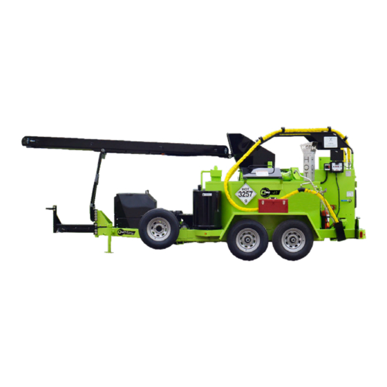
- Page 1 Melter Applicator Magma M4 Dual Pump Owner/Operator Manual 2601 Niagara Lane · Plymouth, MN 55447 · (763) 557-1982 · (877) 841-0848 · Fax (763) 557-1971 Part # 161621 Rev B 1/20/17...
-
Page 2: Table Of Contents
Table of Contents Shipping Papers and Information ............3 Safety Notes ..................4 Weights and Dimensions ..............5 Controls and Their Functions ............6-7 Start Up ..................... 8-9 Automatic Temperature Control Setting .......... 10 Cleanout Procedure ................11 Cleanout Procedure (Non-Electric Hose) ........12-13 Maintenance .................. -
Page 3: Shipping Papers And Information
Shipping Papers and Information A packet containing IMPORTANT INFORMATION has been enclosed with your Melter. This packet contains: Operation Instructions Parts List Warranty Information Manufacturer's Documents Engine Material Pump Burner (Diesel only) IMPORTANT: This manual contains the basic information required to operate, main- tain and repair the CIMLINE Melter you have purchased. -
Page 4: Safety Notes
Safety Notes PLEASE READ AND UNDERSTAND ENTIRE OPERATORS MANUAL BEFORE PROCEEDING WARNING: Protective clothing must be worn. Refer to ANSI Regulations: Wear gloves with wristlets. Wear long sleeve shirt with sleeves rolled down and cuffs buttoned. Wear a face shield. Load Melter from ground level. -
Page 5: Weights And Dimensions
Weights and Dimensions Model Number "A" in/cm "B" in/cm "C" in/cm Weight lbs/kg (empty) 89/226 188/478 93/236 5420/2458 Weights are without options... -
Page 6: Controls And Their Functions
Controls and Their Functions NOTE: This general outline will only familiarize you with the machine. Read through the entire manual before putting this machine into operation. Tank Outlet Valve: Allows melted material from the tank to flow into the pumping sys- tem. - Page 7 Controls and Their Functions...
-
Page 8: Start Up
Start up 1. SETUP: A) Set Flow control to “9” B) Set rotary switch to RUN 2. START ENGINE: A) Turn key on engine control to “1” B) Heat glow plugs 3-5 seconds. C) Turn key to “2” D) Release when engine starts 3. - Page 9 Start up 4. WAND A) Unlock Boom B) Place wand in port. 5. Ready for Work When all 3 GREEN lights are on: A) Set Flow to “0” B) Pin Wand trigger and set handle forward C) Set Flow to “5” D) Close pressure valve to desired material flow level.
-
Page 10: Automatic Temperature Control Setting
Automatic Temperature Control Setting The control system on your CIMLINE “M” series melter has been factory set to run the most common types of materials. These Materials have an application temperature of 380 deg F. With some materials, it may be needed to change the controller to achieve the appropriate appli- cation temperature. -
Page 11: Cleanout Procedure
Cleanout Procedure 1. SETUP: A) Place wand in port. B) Pin wand trigger and set handle for- ward. C) Set rotary switch to “CLEAN OUT” D) Set flow to “9” E) Turn pressure valve all the way clock wise Hose Clean-out: Let pump run in reverse for 2 minutes. -
Page 12: Cleanout Procedure (Non-Electric Hose)
Cleanout Procedure (Non-Electric Hose) Regardless of how you store your hose, the residue tends to settle at the bottom of the coils overnight. Each day when the unit is started, the hose must be coiled up and placed in the cabinet during the preheating process, as shown in the picture be- low. - Page 13 Cleanout Procedure (Non-Electric Hose) NOTE: Immediately coil the hose inside the cabinet. If the unit is not full of material, add material to lower the tank temperature enough so the control box will fire the burner. Keep adding material until the cabinet temperature is high enough to unplug the hose.
-
Page 14: Maintenance
Maintenance Engine: The operation and life of the engine depends on you and your operator. Do not start engine until the engine precheck is complete. The engine precheck consists of checking the oil, the fuel level, the hydraulic oil level and the air filter. The 150/230/410 M/A has the option of (2) different engines. - Page 15 Maintenance 1000 Maintenance Operation Daily 25 Hrs Hrs Yearly Check fuel level (add if low) Check engine and heat transfer oil (add if low) Check hydraulic oil (add if low) Check engine air cleaner Inspect pre-cleaner Cleanout material system Inspect sealing hose and cover Inspect sealing hose connection Drain condensation from air compressor option Blow oil cooler on the air compressor option...
-
Page 16: Fluid And Components Specs
Fluid and Components Specifications Hydraulic Reserve Capacity 30 Gallons Hydraulic Oil Type Conoco MV32 or equiv Diesel Fuel Capacity 30 Gallons Diesel Fuel Type ASTM D975 No.2 Heat Transfer Oil Capacity 36 Gal. Heat Transfer Oil Type See Specs. On next page. Agitation Drive Relief Setting Material Pump Drive Relief Setting Material Pump Displacement... -
Page 17: Heat Transfer Oil Specs
Heat Transfer Oil Specifications ISO Grade 68 Heat transfer Oil Specification There are many different types of Heat Transfer Oils on the international marketplace. It is criti- cal that you use the proper oil to prevent poor performance, oil flashing, or auto-ignition. To conform to most government bids and to supply a readily available product, CIMLINE typically uses brands manufactured by Conoco or Phillips 66 that meet the ISO Grade 68 Heat Transfer Oil specifications listed. -
Page 18: Material Tank Capacity
Material Tank Capacity MATERIAL CAPACITY MATERIAL VAT MODEL 410 13.9 GALLONS PER INCH INSULATION Model 410 Material 3210 Cubic Depth Inches 2" 27.79 4" 55.58 6" 83.38 8" 111.17 10" 138.96 12" 166.75 14" 194.55 16" 222.34 18" 250.13 20" 277.92 22"... -
Page 19: Trouble Shooting Guide
Trouble Shooting Guide Problem Cause Solution Fuse burned out. Check fuse Burner relay inoperative. Check for 12VDC at relay. Burner will not ignite Primary control fuse. Check fuse Thermocouple(s) inoperative Replace thermocouple(s) Fuse burned out. Check fuse Sealant material not hot enough. Allow material to heat longer Too many biscuits added at one Continue heat up and reverse agitation... -
Page 20: Parts Section
Parts Section... -
Page 21: Wiring Diagrams
Complete Wiring Diagram... -
Page 22: Engine Harness
Wiring Diagrams Engine Harness... -
Page 23: Control Panel
Wiring Diagram Switch Plate... - Page 24 Wiring Diagram Switch Plate...
-
Page 25: Main Supply Harness
Wiring Diagrams Main Supply Harness... -
Page 26: Burner
Wiring Diagrams Burner... -
Page 27: Dual Heater Hose Relay Panel
Wiring Diagrams Dual Heater Hose Relay Panel Item Part # Description Item Part # Description 130385 Generator 130370 Curcuit Breaker 405268 Gen Mount Weld 12 404811s Temp Control Panel 405928 Gen Mount Weld (engine side) 421400 Control Box Lid 111409 Pulley 420314 Door Stop 405269 Top Gen Tightener Weld 153814 Latch... -
Page 28: Dual Heated Hose Control Panel
Wiring Diagrams Dual Heated Hose Control Panel... -
Page 29: Hydraulic Schematic
Hydraulic Schematic For Compressor Hydraulics, see Supplement manual... -
Page 30: Hydraulic Manifold Components
Hydraulic Manifold Components Item Part # Description 172371 Hyd. Manifold 171597 Guage 172587 Relief Valve (Set at 800 PSI) 172226 Spool and Coil Kit for Matl Pump 172224 Spool for Matl Pump 172225 Coil for Matl Pump (2 req'd) 172589 Spool and Coil Kit for TFC 172557 Spool for TFC 172585 Coil for TFC 172583 Spool and Coil Kit for Agitator... -
Page 31: Hydraulic Schematic - Dual Pump Option
Hydraulic Schematic - Dual Pump Option For Compressor Hydraulics, see Supplement manual... -
Page 32: Electrical Components
Electrical Components... -
Page 33: Engine Components
Engine Components Item Part # Description Item Part # Description Engine (Compressor with Heat- 111828 13 155266 Key ed Hose Generator) Engine (Compressor with-out 111727 14 111337 Oil Filter (Non-Compressor Engine) Heated Hose Generator) 111372 Fan Belt 15 111457 Fuel Filter (Non-Compressor Engine) Dual Hydraulic Pump (Non-compressor 153619 Exhaust (Compressor Engine) Engine) - Page 34 Engine Components...
-
Page 35: Material Plumbing Components
Material Plumbing Components... - Page 36 Material Plumbing Components...
-
Page 37: Material Pump Parts List
Material Pump Parts List (For Reference Only—We do not stock rebuild parts) 120803 (20 GPM) & 154151 (30 GPM) - Page 38 Material Pump Parts List (For Reference Only—We do not stock rebuild parts)
-
Page 39: Sealing Hose & Wand
Sealing Hose & Wand Item Part # DESCRIPTION Item Part # DESCRIPTION 407863 Wand Sub weld 407872 Support Handle 170635 Live Swivel 426987 Spacer 407862 Handle Weld 155297 Spring 120412 Pipe Nipple 427116 Spring Guard 120560 Ball Valve 155272 Metal Sleeve 130323 Switch (qty 2) 111725... -
Page 40: Sealing Wand Attachments
Sealing Wand Attachments * 2.5" wide band PIVOTING SHOE / 403137 * 3/4" NPT inlet * Open shoe design for clear visibility of material * Pivoting inlet tube maintains contact with the road. * 2" or 3" wide band SEALING DISC 3.5” / 403162 * 3/4"... -
Page 41: Agitation System Parts List
Agitation System Parts List Item Description Item Description 404325 Agitator - 410 404327 Agitator Motor Mount - 410 420170S Cover 420171 Adjustment Angle 110488 Chain 100295 3/8 x 3 Full Thread Bolt 111087 Sprocket - 50BS30 x 1.50 111088 Sprocket - 50BS14 x 1 170602 Motor, Agitation - 410 171173 Load Adapter 171081 Seal Kit For 170602... -
Page 42: Oil Burner Parts List
Oil Burner Parts List Item Part # Description 404388 410 Oil Burner, Complete 153445 Nozzle, 2.25 GPH x 90B Model 410 153505 Square Plate , Gasket 152191 Motor, Oil Burner 155001 Pump, Oil 152106 Electrode Rod/Ins Assy 152128 Gasket, Burner Flange 152173 Ignition Transformer Assy. -
Page 43: Combustion Chamber Parts List And Tank Insulation
Combustion Chamber Parts List and Tank Insulation... -
Page 44: Hydraulic Reservoir And Diesel Tank Components
Hydraulic Reservoir and Diesel Tank Components Item Part # Description 172618 Hydraulic Tank 172619 Diesel Tank 172127 Return Filter Assy (Non-Compressor) 172185 Return Filter Assy (Compressor) 170407 Element - Return Filter (Non-Compressor) Element - Return Filter (Compressor) 152044 Filler Cap Assy 171631 Sight Gauge 172186 Suction Strainer 155396 Fuel Gauge/Cap... -
Page 45: Misc. Parts
Miscellaneous Parts Item Part # Description 161325 Label 140333 Pintle Hitch, 2 1/2" 403135 Pintle Hitch, 3" 403271 Ball Hitch, 2" (110 only) 402954 Ball Hitch, 2 5/16" 150212 Battery, 12 V-M 140330 Jack - 5000 lb. 140381 Radial Tire R15 (410 only) 404341 Dipstick/Cap Assy 422512... -
Page 46: Spare Parts Kit
Spare Parts Kit Option Item Part # Description 152105 Electric Eye 200352 Primary Control 130113 Relay (Heated Hose & Burner) 152399 Coupling 200482 Controller 153537 Fuse 10 Amp (Qty 5) 130097 Thermocouple (Oil) 153621 Thermocouple (Pump) 153644 Fuse ABC 15 404695 Complete Spare Parts Kit 2,6,9... - Page 47 Notes...
- Page 48 2601 Niagara Lane · Plymouth, MN 55447 · (763) 557-1982 · (800) 328-3874 · Fax (763) 557-1971...
Need help?
Do you have a question about the Magma M4 and is the answer not in the manual?
Questions and answers