Advertisement
Available languages
Available languages
Quick Links
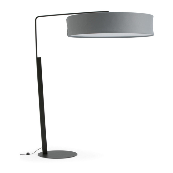
Campfire
Big Lamp
™
©
2010 Steelcase Inc.
Grand Rapids, MI 49501 U.S.A.
Printed in U.S.A.
1
All electrical installations must be done by qualified personnel in accordance
with codes and regulations applicable at the installation site.
2
Before beginning work, ensure that the electrical power has been removed
from the circuits that are being connected to or disconnected from.
WARNING:
To Prevent Risk
3
Ensure that circuits to which the lights are connected are properly grounded
and are the correct voltage.
of Electrical Shock . . .
4
To prevent wiring damage or abrasion, do not expose wiring to edges of
sheet metal or other sharp objects.
Application Note: Consult your local fire code authorities
when planning the use of this product in a building with
sprinklers. Some authorities may limit the use of the Big Lamp
in close proximity to sprinkler heads due to the large shade
being an obstruction in the sprinkler spray pattern.
R
#2 and #3 Philips
Screwdrivers
English - Page 1 of 10 of 30
French - Page 11 of 20 of 30
Spanish - Page 21 of 30 of 30
939500548 Rev B
Advertisement

Related Manuals for Turnstone Campfire Big Lamp

Summary of Contents for Turnstone Campfire Big Lamp
- Page 1 Campfire Big Lamp ™ #2 and #3 Philips Screwdrivers All electrical installations must be done by qualified personnel in accordance with codes and regulations applicable at the installation site. Before beginning work, ensure that the electrical power has been removed from the circuits that are being connected to or disconnected from.
- Page 2 Important Safety Instructions: This portable luminaire has a polarized plug (one blade is wider than the other) as a feature to reduce the risk of electric shock. This plug will fit in a polarized outlet only one way. If the plug does not fit fully in the outlet, reverse the plug. If it still does not fit, contact a qualified electrician.
- Page 3 Contents Box #1 Box #2 Box #3 Base Assembly Lamp Upper Section Shade and Diffuser Assemblies 5/16-18 #6 COVER #10-24 X 1/2" SCREW SCREW SCREW BASE (QTY 4) (QTY 1) (QTY 8) (QTY 1) SHADE ASSEMBLY (QTY 1) UPPER BOOM (QTY 1) CANTILEVER (QTY 2)
- Page 4 5/16-18 FLAT HEAD SCREW Assemble the base to the post using three (3) 5/16-18 flat head screws (1a). Tighten using a #3 phillips screwdriver (1b). Start four (4) #10-24 x 1/2" adjusting screws into the boom plate. Feed the cord into the post until the top electrical connector is exposed.
- Page 5 Connect electrical connectors together. Push the connector partially inside the boom tube. CORD ELECTRICAL CONNECTOR BOOM CORD ELECTRICAL CONNECTOR POST BOOM TUBE Page 5 of 30 POST 939500548 Rev B...
- Page 6 Fully insert the boom Assemble the lock plate into the notch tube into the post up to the (6a). Insert and tighten one (1) 5/16-18 notch in the tube, while screw (6b). Do not over tighten. allowing excess cord to feed out the base of the lamp.
- Page 7 Assemble cantilever to hub by placing hooks on bottom of hub into rectangular holes in cantilever and rotating into position. Install #10-24 x 1/2" SCREW and tighten four (4) #10-24 x 1/2" screws. CANTILEVER Page 7 of 30 939500548 Rev B...
- Page 8 SLOT NOTE: The Shade and Diffuser are packaged folded up. Their spring SHADE steel support rings can unfold rapidly. Hold them out and away from you and TOP RING others as you unfold them. Unfold the shade and confirm the slots in the fabric are visible in the top and bottom rings.
- Page 9 SHADE/CANTILEVER ASSEMBLY Lift the shade/cantilever assembly to align the notch in the cantilever assembly with the boom post (12a). Lower the shade assembly onto the boom post (12b). Adjust the four leveling BOOM POST screws to level the shade assembly. BOOM POST NOTE: Cantilevers and hub...
- Page 10 Install a 100 watt or smaller, 120 volt, Type A19 incandescent light bulb (not provided). Unfold the diffuser and insert the 4 clips in the slots on the bottom ring. DIFFUSER DIFFUSER SLOT ON BOTTOM RING Page 10 of 30 939500548 Rev B...
- Page 11 Grande lampe Campfire ™ Tournevis Phillips n° 2 et 3 L'installation des appareils électriques doit être confiée à du personnel qualifié; elle doit en outre être effectuée conformément aux codes et aux règlements en vigueur. Avant de commencer les travaux, assurez-vous d'avoir coupé le courant aux circuits à...
- Page 12 Importantes directives de sécurité: Ce luminaire portatif est doté d'une fiche polarisée (l'une des lames est plus grande que l'autre) afin de réduire les risques de choc. Cette fiche s'insère d'une seule manière dans une prise polarisée. Si la fiche ne s'insère pas complètement dans la prise, retournez- la.
- Page 13 Contenu Boîte #1 Boîte #2 Boîte #3 Base Section supérieure du luminaire Abat-jour et diffuseur VIS DU 5/16-18 COUVERCLE N° 6 #10-24, 1/2 PO BASE (QTÉ 4) (QTÉ 1) (QTÉ 8) (QTÉ 1) ABAT-JOUR (QTÉ 1) BRAS SUPÉRIEUR (QTÉ 1) BRAS CANTILEVER (QTÉ...
- Page 14 VIS À TÊTE PLATE 5/16-18 Fixez la base au poteau au moyen des trois vis à tête plate 5/16-18 (1a). Serrez au moyen d'un tournevis Phillips n°3 (1b). Insérez quatre vis de réglage 10-24, 1/2 po dans la plaque du bras. Faites passer le cordon dans le poteau jusqu'à...
- Page 15 Branchez ensemble les connecteurs électriques. Enfoncez légèrement les connecteurs dans l'extrémité du tube du bras. CONNECTEUR ÉLECTRIQUE DU CORDON CONNECTEUR ÉLECTRIQUE DU CORDON DU BRAS POTEAU TUBE DU BRAS Page 15 of 30 POTEAU 939500548 Rev B...
- Page 16 Insérez complètement le Insérez la plaque de blocage dans la rainure (6a). tube du bras dans le poteau Insérez, puis serrez une vis 5/16-18 (6b). Évitez de jusqu'à la rainure dans le trop serrer. tube en laissant l'excès de cordon s'écouler vers la Installez la plaque du couvercle, puis alignez-la base.
- Page 17 Fixez le cantilever au moyeu en insérant les crochets à la base du moyeu dans les orifices rectangulaires en cantilever, puis VIS 10-24, 1/2 PO faites-le pivoter en position. Installez, puis serrez les quatre vis 10-24, 1/2 po. CANTILEVER MOYEU Page 17 of 30 939500548 Rev B...
- Page 18 FENTE REMARQUE: L'abat jour et le diffuseur sont emballés pliés. Leur support à ressort d'acier ABAT-JOUR peut se détendre rapidement. Tenez-les fermement loin de vous et des autres personnes ANNEAU lorsque vous les dépliez. SUPÉRIEUR Dépliez l'abat-jour et assurez-vous que les fentes dans le tissu sont visibles sur les anneaux supérieurs et inférieurs.
- Page 19 ABAT-JOUR/ CANTILEVER Soulevez l'abat-jour et le cantilever de manière à aligner la rainure du cantilever avec le bras du poteau (12a). Abaissez l'abat-jour sur le bras du poteau (12b). Rajustez les vis de BRAS DU POTEAU réglage pour mettre l'abat-jour de niveau.
- Page 20 Installez une lampe de type A19, de 100 watts ou moins, 120 volts (non fournie). Dépliez le diffuseur et insérez les quatre languettes dans l'anneau inférieur. DIFFUSEUR DIFFUSEUR FENTE DE L'ANNEAU DU BAS Page 20 of 30 939500548 Rev B...
- Page 21 Lámpara grande Campfire ™ Destornilladores Phillips Nº2 y Nº3 Todas las instalaciones eléctricas deben ser hechas por personal calificado de acuerdo con las normas y reglamentos aplicables en el sitio de instalación. Antes de empezar el trabajo, esté seguro de haber quitado toda la energía eléctrica en los circuitos que están siendo conectados a ó...
- Page 22 Instrucciones importantes de seguridad: Esta luminaria portátil tiene un enchufe polarizado (una clavija es más ancha que la otra), particularidad que reduce el riesgo de sacudida eléctrica. Este enchufe encaja en un tomacorriente polarizado sólo de una manera. Si el enchufe no encaja completamente en el tomacorriente, invierta el enchufe.
- Page 23 Contenido Caja Nº 1 Caja Nº 2 Caja Nº 3 Conjunto base Sección superior de la lámpara Conjunto pantalla y difusor Tornillo de Tornillo de Tornillo Nº 10 18 x 5/16 la tapa Nº 6 de 24 x ½ pulgadas BASE (CANTIDAD 4) (CANTIDAD 1)
- Page 24 TORNILLO DE CABEZA PLANA DE 18 X 5/16 Ensamble la base al montante con los tres (3) tornillos de cabeza plana de 18 x 5/16 pulgadas (1a). Apriete con un destornillador Phillips Nº 3 (1b). Empiece poniendo los cuatro (4) tornillos de regulación Nº 10 de 24 x 1/2 pulgadas en la plancha del brazo.
- Page 25 Conecte entre sí los conectores eléctricos. Empuje parcialmente el conector dentro del tubo del brazo. CONECTOR ELÉCTRICO DEL CABLE CONECTOR ELÉCTRICO DEL CABLE DEL BRAZO MONTANTE TUBO DEL BRAZO Page 25 of 30 MONTANTE 939500548 Rev B...
- Page 26 Inserte completamente el Ensamble la plancha de enganche en la tubo del brazo en el muesca (6a). Inserte y apriete un (1) tornillo de montante hasta la muesca 18 x 5/16 pulgadas (6b). No apriete demasiado. del tubo, dejando que el exceso del cable pase hacia Instale la tapa y alinéela con el montante.
- Page 27 Ensamble el cantilever en el cubo colocando los ganchos de la parte inferior del cubo en los orificios rectangulares del cantilever TORNILLO Nº 10 DE 24 X 1/2 PULGADA y girándolos a su posición. Instale y apriete los cuatro (4) tornillos Nº 10 de 24 x 1/2 pulgada.
- Page 28 RANURA NOTA: La pantalla y el difusor se embalan completamente enrollados. Sus anillos de PANTALLA soporte en acero para resorte pueden desenrollarse rápidamente. Sosténgalos ANILLO alejados de usted o de otros SUPERIOR mientras los desenrolla. Desenrolle la pantalla y confirme que las ranuras del material estén visibles en los anillos superior e inferior.
- Page 29 CONJUNTO PANTALLA/CANTILEVER Levante el conjunto pantalla/cantilever para que la muesca del conjunto cantilever quede alineada con el montante del brazo (12a). Baje el conjunto pantalla sobre el montante del brazo. MONTANTE DEL BRAZO Regule los cuatro tornillos de nivelación para nivelar el conjunto pantalla.
- Page 30 Instale una bombilla de 100 vatios o menos, 120 voltios del tipo A19 (no provista). Desempaque el difusor e inserte las cuatro presillas en las ranuras del anillo inferior. DIFUSOR DIFUSOR RANURA DEL ANILLO INFERIOR Page 30 of 30 939500548 Rev B...
Need help?
Do you have a question about the Campfire Big Lamp and is the answer not in the manual?
Questions and answers