Table of Contents
Advertisement
Aircraft General Description.................................................................... 1-1
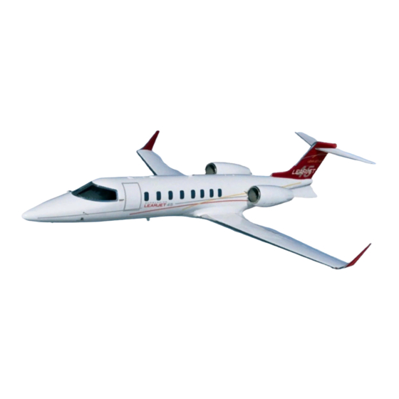
Airplane Three-View (Figure 1-1)........................................................ 1-2
General Arrangement - Exterior (Figure 1-2).................................. 1-3
Cabin Entry Door ..................................................................................... 1-5
Entry Door Annunciations ................................................................... 1-6
Cabin Door Operation........................................................................... 1-8
To Open Cabin Door From the Outside......................................... 1-8
Opening Cabin Door (From Outside) (Figure 1-3)....................... 1-8
To Close Cabin Door From the Inside............................................ 1-9
(Lower Door From Inside) (Figure 1-4) ......................................... 1-9
(Upper Door From Inside) (Figure 1-5) ....................................... 1-10
Cabin Door Closed and Latched Verification ............................. 1-11
Cabin Door Latch Pin Sight Windows (Figure 1-6) ................... 1-11
To Open Cabin Door From the Inside.......................................... 1-13
Opening Cabin Door (From Inside) (Figure 1-7)........................ 1-13
To Close Cabin Door From the Outside....................................... 1-14
Closing Cabin Door (From the Outside) (Figure 1-8)................ 1-14
Emergency Exits ...................................................................................... 1-15
Left Forward Emergency Exit ............................................................ 1-15
Left Forward Emergency Exit Operation ......................................... 1-16
Left Forward Emergency Exit Operation (Figure 1-9).................... 1-16
Right Aft Emergency Exit Hatch ....................................................... 1-17
Aft Emergency Exit Security Pin (Figure 1-10)................................ 1-17
Right Aft Emergency Exit Hatch Operation .................................... 1-18
From the Inside .................................................................................... 1-18
From the Outside ................................................................................. 1-19
(From the Outside) (Figure 1-12) ....................................................... 1-19
From the Inside .................................................................................... 1-20
Right Aft Emergency Exit Annunciations ........................................ 1-20
PM-126A
GENERAL DESCRIPTION
TABLE OF CONTENTS
Pilot's Manual
SECTION I
I
1
-
Advertisement
Chapters
Table of Contents

Subscribe to Our Youtube Channel
Related Manuals for BOMBARDIER LEARJET 45


Summary of Contents for BOMBARDIER LEARJET 45
-
Page 1: Table Of Contents
Pilot’s Manual SECTION I GENERAL DESCRIPTION TABLE OF CONTENTS Aircraft General Description..............1-1 Airplane Three-View (Figure 1-1)............1-2 General Arrangement — Exterior (Figure 1-2)........1-3 Cabin Entry Door ..................1-5 Entry Door Annunciations ..............1-6 Cabin Door Operation................1-8 To Open Cabin Door From the Outside......... 1-8 Opening Cabin Door (From Outside) (Figure 1-3)....... - Page 2 Pilot’s Manual TABLE OF CONTENTS (Cont) External Doors ..................1-21 Baggage Compartment Door............. 1-21 Tailcone Access Door ................1-21 External Doors Annunciations ............1-21 External Service Doors................ 1-21 Oxygen Service Door ..............1-21 Fuselage Fuel Gravity Fill Access Door ........1-22 Single-Point Pressure Refueling Access Door ......
-
Page 3: Aircraft General Description
SECTION I GENERAL DESCRIPTION AIRCRAFT GENERAL DESCRIPTION The Learjet 45 aircraft, manufactured by Learjet Inc., is an all metal, pressurized, low-wing, turbofan-powered monoplane. The high-aspect ratio, fully cantilevered, swept-back wings with winglets are of conven- tional riveted construction except for the upper section of the winglets, which utilize full-depth honeycomb core bonded to the outer skin. - Page 4 Pilot’s Manual NOTE: All dimensions shown for aircraft in static position. 14 ft 1 in (4.29 m) 54 ft 0 in (16.46 m) 58 ft 5 in (17.81 m) 17 ft 2 in (5.24 m) 9 ft 4 in (2.85 m) A06-0002 47 ft 10 in F45-000000-101...
-
Page 5: General Arrangement - Exterior (Figure 1-2)
Pilot’s Manual GENERAL ARRANGEMENT —EXTERIOR Figure 1-2 1 - 11/ 1 - 12 (Blank) PM-126A 1-3/ 1-4 (Blank) -
Page 7: Cabin Entry Door
Pilot’s Manual CABIN ENTRY DOOR The cabin door is located in the forward left side of the fuselage. The cabin door is a clamshell style design which consists of an upper door section which opens upward to form a canopy while open, and a lower door section with integral steps which opens downward. -
Page 8: Entry Door Annunciations
Pilot’s Manual CABIN ENTRY DOOR (CONT) A cable and knob assembly is attached to the forward side of the lower door frame.The cable and knob assembly is used to raise and lower the lower door from inside the cabin. When closing the lower cabin door, a secondary latch will automatically engage and hold the lower door in position against the door seal until the lower door handle is rotated forward to the locked position. - Page 9 Pilot’s Manual ENTRY DOOR ANNUNCIATIONS (Cont) A white ENTRY DOOR PIN message will illuminate on the CAS whenever the aircraft is on the ground and the cabin door pins are not all fully engaged or all not fully disengaged. The ENTRY DOOR CWP message will be simultaneously displayed with the ENTRY DOOR PIN CAS message.
-
Page 10: Cabin Door Operation
Pilot’s Manual CABIN DOOR OPERATION To open the cabin door from the outside: 1. Insert the key in the key lock and rotate to unlock. 2. Lift the upper door handle out and rotate the handle clockwise with both hands to the stop, releasing the door latch pins. 3. -
Page 11: To Close Cabin Door From The Inside
Pilot’s Manual CABIN DOOR OPERATION (CONT) To close cabin door from the inside: The flip-down step could cause injury to the hand or WARNING fingers if it is allowed to suddenly swing down into the stowed position. The flip-down step must be grasped firmly as the door is raised, and lowered by hand before the step nears the vertical position. -
Page 12: Closing Cabin Door (Upper Door From Inside) (Figure 1-5)
Pilot’s Manual CABIN DOOR OPERATION (CONT) 4. Pull the upper door down until the upper door handle is within reach. 5. With the upper door handle in the OPEN position (with the handle pointing up), pull the door tightly against the door seal and rotate the locking handle forward (clockwise) to the locked position. -
Page 13: Cabin Door Closed And Latched Verification
Pilot’s Manual CABIN DOOR OPERATION (CONT) Cabin Door Closed and Latched Verification: The cabin door is equipped with thirteen sight windows located in the cabin door panels (nine in the upper door and four in the lower door). The sight windows allow verification from inside the cabin that the cabin door pins are properly engaged with the fuselage structure and that the lower lock and middle lock pins are properly engaged. -
Page 15: To Open Cabin Door From The Inside
Pilot’s Manual CABIN DOOR OPERATION (CONT) To open cabin door from the inside: 1. Lift the upper door locking handle into the OPEN position. 2. Push the upper door outward and up allowing the door struts to raise the upper door to the fully open position. 3. -
Page 16: To Close Cabin Door From The Outside
Pilot’s Manual CABIN DOOR OPERATION (CONT) To close the cabin door from the outside: 1. Pivot the flip-down step upward until the step rests against the lower door. 2. Raise the lower door until it is against the door seal and secondary latch engages. -
Page 17: Emergency Exits
Pilot’s Manual EMERGENCY EXITS LEFT FORWARD EMERGENCY EXIT The upper portion of the cabin entry door serves as the left forward emergency exit. The upper cabin entry door/left forward emergency exit is secured to the fuselage by six latching pins which extend from the left forward emergency exit into the fuselage structure and by two latching pins which are driven from the left forward emergency exit into an overlapping section in the lower cabin entry door. -
Page 18: Left Forward Emergency Exit Operation
Pilot’s Manual LEFT FORWARD EMERGENCY EXIT OPERATION To open from the inside: 1. Lift the upper cabin door handle (rotate counterclockwise) into the OPEN position. 2. Push the upper door outward and up allowing the door struts to raise the upper door to the fully open position. 3. -
Page 19: Right Aft Emergency Exit Hatch
Pilot’s Manual RIGHT AFT EMERGENCY EXIT HATCH The emergency exit hatch is located on the right aft side of the cabin near the leading edge of the wing, adjacent to the right aft passenger seat. It provides egress from the cabin in the event of an emergency. The hatch is secured to the airframe by two spring-loaded pins which extend from the top of the hatch into the fuselage structure. -
Page 20: Right Aft Emergency Exit Hatch Operation
Pilot’s Manual RIGHT AFT EMERGENCY EXIT HATCH OPERATION To open/remove the right aft emergency exit from the inside: 1. Remove the handle cover from the emergency exit hatch to fully expose the emergency exit handle. The cover is attached with hook and loop fasteners and can be easily pulled from the hatch. -
Page 21: To Open/Remove The Emergency Exit Hatch From The Outside
Pilot’s Manual EMERGENCY EXIT HATCH OPERATION (CONT) To open/remove the emergency exit hatch from the outside: 1. Locate the emergency exit hatch latch. The latch is located above the window in the emergency exit door, immediately above the placard that reads “EMERGENCY DOOR PUSH TO OPEN DOOR OPENS INWARD”. -
Page 22: Installing The Right Aft Emergency Exit Hatch From The Inside
Pilot’s Manual Installing the right aft emergency exit hatch from the inside: The emergency exit hatch is designed to be installed NOTE from inside the cabin only. Ensure the seat next to the emergency exit hatch is positioned in the fully inboard position before installing the hatch. -
Page 23: External Doors
Pilot’s Manual EXTERNAL DOORS BAGGAGE COMPARTMENT DOOR The baggage compartment door provides access to the baggage compartment and is located on the left side of the fuselage below the left engine nacelle. The door is 33 inches (84 centimeters) wide and is hinged on the forward side. -
Page 24: Fuselage Fuel Gravity Fill Access Door
Pilot’s Manual EXTERNAL SERVICE DOORS (CONT) FUSELAGE FUEL GRAVITY FILL ACCESS DOOR The fuselage fuel gravity fill access door is located on the right side of the fuselage. This door is hinged at the top, has a spring-loaded latch at the bottom edge, and opens upward. -
Page 25: Turning Radius (Figure 1-13)
Pilot’s Manual 39 FT 4 in (12.0 m) NOSE WHEEL WING TIP NOTE: Turning radius expressed above is based upon 60° nose-wheel deflection. TURNING RADIUS Figure 1-13 A09-2001 1-23 PM-126A... -
Page 26: Danger Areas (Figure 1-14)
Pilot’s Manual 15 feet (4.57 m) WEATHER RADAR ENGINE INTAKE 12 feet (3.66 m) 12 feet (3.66 m) from intake from intake APU EXHAUST APU INTAKE ENGINE EXHAUST 750° F (399° C) Exhaust danger area shown for idle RPM. Values approximately double for takeoff RPM. -
Page 27: Instrument Panel (Typical) (Figure 1-15)
Pilot’s Manual 16 17 .4 .4 .4 .4 1. Pilot’s Rudder Pedal Adjustment 12. Flight Guidance Controller 23. Copilot’s Audio Control Panel 2. Pilot’s Crew Lighting Panel 13. Standby Instruments 24. #2 AHRS Mode Control 3. #1 AHRS Mode Control 14. -
Page 29: Pedestal (Typical) (Figure 1-16)
Pilot’s Manual 1. Pitch Trim Bias Switch 2. Clearance Delivery Radio (CDR) 3. Gear Freefall Lever 4. Ground Proximity Warning System Switches (opt) 5. Thrust Reverser Levers 6. Thrust Levers 7. Flap Lever 8. MFD Joystick 9. HF Control Panel 10. - Page 30 Pilot’s Manual INTENTIONALLY LEFT BLANK 1-28 PM-126A...
-
Page 31: Pilot's Circuit Breaker Panel (Typical) (Figure 1-17)
Pilot’s Manual AVIONICS INSTRUMENTS/INDICATIONS GEAR/HYDRAULICS FLIGHT ELECTRICAL COMMUNICATIONS DISPLAY NOSE STEER L AV BUS AUDIO 1/ L WARN ELEV L WHL STALL SELCAL HF 1 ATC 1 COMM 1 CLR DLY PANEL L CTRL DU 1 DU 2 SG 1 MOTOR CMPTR SQUAT... -
Page 33: Copilot's Circuit Breaker Panel (Typical) (Figure 1-18)
Pilot’s Manual AVIONICS ELECTRICAL FLIGHT GEAR INSTRUMENTS/INDICATIONS /HYD R AV BUS DISPLAY COMMUNICATIONS STALL R WHL R WARN HOUR MAIN R GEN WARN MSTR FORCE SQUAT SG 2 DU 3 DU 4 R CTRL PANEL METER AUDIO 2 COMM 2 ATC 2 HF 2 COMM 3... - Page 35 Pilot’s Manual SECTION II ENGINES & FUEL TABLE OF CONTENTS Engines......................2-1 Fuel Control Logic Diagram (Figure 2-1) ........... 2-2 Engine Fuel and Control System............. 2-3 Thrust Levers..................2-3 Engine-Driven Fuel Pump..............2-4 Hydromechanical Fuel Control Unit ..........2-4 Digital Electronic Engine Control (DEEC) ......... 2-5 Automatic Performance Reserve (APR)..........
- Page 36 Pilot’s Manual TABLE OF CONTENTS (Cont) Engine Fire Extinguishing System............2-22 L and R Engine Fire and Extinguisher #1/#2 Switches ....2-23 Fire Extinguisher Discharge Indicators ..........2-23 Fire Extinguishing System (Figure 2-3) ........... 2-24 Thrust Reversers ..................2-25 Thrust Reverser Levers............... 2-26 Thrust Reverser Indications...............
-
Page 37: Engines
Pilot’s Manual SECTION II ENGINES & FUEL ENGINES The aircraft is powered by two TFE731-20 turbofan engines manufac- tured by Honeywell. These engines are two-spool, geared transonic- stage, front-fan, jet-propulsion engines. Each engine is rated at 3500 pounds (15.56 kN) thrust at sea level. A spinner and an axial-flow fan are located at the forward end of the engine and are gear driven by the low-pressure (N ) rotor. -
Page 38: Fuel Control Logic Diagram (Figure 2-1)
Pilot’s Manual SURGE BLEED SYSTEM DIGITAL ELECTRONIC ENGINE CONTROL HYDROMECHANICAL FUEL CONTROL UNIT W F /P (Secondary) TLA (Secondary) TLA (Primary) AIR DATA MACH, ALTITUDE, T COMPUTER FUEL ELECTRICAL MECHANICAL A B — AREA BLEED N 1 — LOW PRESSURE ROTOR (FAN) SPEED N 2 —... -
Page 39: Engine Fuel And Control System
Pilot’s Manual ENGINE FUEL AND CONTROL SYSTEM The engine fuel and control system pressurizes fuel routed to the en- gine from the aircraft fuel system, meters fuel flow, filters the fuel, heats it as necessary to prevent filter icing, and delivers atomized fuel to the combustion section of the engine. -
Page 40: Engine-Driven Fuel Pump
Pilot’s Manual ENGINE-DRIVEN FUEL PUMP The engine-driven fuel pump provides high-pressure fuel to the engine fuel control system as well as motive-flow fuel for operation of the air- craft jet pumps. The pump consists of a low-pressure pump element, high-pressure pump element, high-pressure relief valve, filter, filter by- pass valve, and motive-flow provisions. -
Page 41: Digital Electronic Engine Control (Deec)
Pilot’s Manual DIGITAL ELECTRONIC ENGINE CONTROL (DEEC) A DEEC is provided for each engine. The DEEC is basically an N gov- ernor with provisions for fuel limits during acceleration and decelera- tion. The DEEC performs governing, limiting, and fuel scheduling functions for engine start and continuous operation. - Page 42 Pilot’s Manual The DEEC has an extensive self-monitoring and fault analysis system. In the event a minor fault is detected in the system, the DEEC will ini- tiate an ENGCMPTR FAULT white CAS when ENG CMPTR switch is in the ON position. If electrical power to the computer is lost, the man- ual mode solenoid valve is deenergized closed, engine control reverts to manual mode, and an ENGCMPTR FAULT amber CAS illuminates.
-
Page 43: Automatic Performance Reserve (Apr)
Pilot’s Manual AUTOMATIC PERFORMANCE RESERVE (APR) Automatic Performance Reserve (APR) provides a change in thrust on the operating engine in the event of opposite engine thrust loss during takeoff and missed approach conditions. The APR is controlled by the APR switch located on the aft portion of the pedestal. Depressing the switch illuminates the white ARM on the switch and the DEEC per- forms a software verification. -
Page 44: Eng Cmptr Switches
Pilot’s Manual Synchronization is accomplished by maintaining the speed of the slave engine in sync with the speed of the master engine. The master engine is determined and so designated during installation. The following criteria must be satisfied before the system will operate: •... -
Page 45: Surge Bleed Control
Pilot’s Manual SURGE BLEED CONTROL A surge bleed control system for each engine is installed to prevent low-pressure compressor surge. Each system consists of two externally mounted surge valve control solenoids and an internally mounted surge bleed valve. During normal operation, surge bleed valve position is controlled by the DEEC via the solenoid control valves. -
Page 46: Engine Oil System
Pilot’s Manual ENGINE OIL SYSTEM Oil for engine lubrication is drawn from the engine oil tank by the oil pump. The oil is output from the pump through a filter, a pressure reg- ulator valve, an oil-to-air cooler, and a fuel heater/oil cooler. The oil-to- air cooler is a three-segment, finned cooler that forms the inner surface of the fan duct. -
Page 47: Engine Oil System Schematic (Figure 2-2)
Pilot’s Manual BREATHER VENT TO AMBIENT PRESSURIZING OIL SUPPLY LINE VALVE OIL PRESSURE LINE OIL LEVEL SIGHT PLUG OIL SCAVENGE LINE NO. 4 AND NO. 5 FILL PORT BEARING CAVITY VENT LINE ELECTRICAL LINE CAS MESSAGES TRANSFER ACCESSORY FAN REDUCTION ALTITUDE GEARBOX DRIVE GEARBOX... -
Page 48: Engine Ignition And Start Systems
Pilot’s Manual ENGINE IGNITION AND START SYSTEMS IGNITION SYSTEM The engine ignition system is an integral sub-system of the engine. Each engine consists of an ignition unit, two ignitor plugs, two shielded high-voltage output cables and associated aircraft wiring. During nor- mal engine operation the system is controlled by the DEEC and is capa- ble of continuous operation. -
Page 49: Engine Start System
Pilot’s Manual ENGINE START SYSTEM A combined starter/generator is mounted on the front of the accessory gearbox. For normal starts, the DEEC provides for automatic starting which allows the thrust lever to be moved into the IDLE position before activating the starter. When the respective L or R START switch is mo- mentarily depressed, the DEEC begins the start sequence by activating the corresponding standby fuel pump and energizing the starter relay closed. -
Page 50: Engine Indicating (Ei)
Pilot’s Manual ENGINE INDICATING (EI) ENGINE VIBRATION MONITOR The engine vibration monitor system consists of an accelerometer mounted on each engine and a tailcone-mounted engine vibration monitor signal conditioner. The vibration monitor signal conditioner consists of two identical independent channels. Each channel is powered by the corresponding 3-amp L or R VIB MON circuit breaker located within the ENGINE group of the respective pi- lot’s or copilot’s circuit breaker panels. -
Page 51: Oil Pressure Indicator
Pilot’s Manual OIL PRESSURE INDICATOR Oil pressure is displayed for each engine as a digital readout on EICAS. The display consists of an OIL PSI legend with pressure readouts to the left and right. Refer to the following table for pressure ranges and corresponding col- or display during normal engine operation: WHITE AMBER... -
Page 52: N 2 Indicators
Pilot’s Manual INDICATORS is displayed for each engine as a digital readout. The display con- sists of an N legend with digital readouts to the left and right. Refer to the following table for N speeds and corresponding color display for various conditions. - Page 53 Pilot’s Manual Aircraft 45-002 & Subsequent modified by SB 45-72-1: OPERATING WHITE AMBER MODE °C °C °C Start 0 to 991 992 to 1014 Takeoff (no anti-ice) 0 to 991 992 to 1014 (<5 minutes) Takeoff (any anti-ice) 0 to 991 992 to 1014 (<5 minutes) Takeoff or APR...
-
Page 54: Engine Diagnostic System (Eds)
Pilot’s Manual ENGINE DIAGNOSTIC SYSTEM (EDS) An Engine Diagnostic System (EDS) is installed to provide engine fault recording and condition trend monitoring. The system periodically records engine parameters and allows the crew to request that condi- tions be recorded at any time. Normal use of the system entails down- loading data from the DEEC and submitting to the engine manufacturer for timely analysis. -
Page 55: Engine Fire Detection System
Pilot’s Manual ENGINE FIRE DETECTION SYSTEM Three heat-sensing elements connected in series are located in each en- gine nacelle to detect an engine fire. One element is located around the accessory gearbox; one is located around the engine tailcone; and an- other around the engine firewall. -
Page 56: Sys Test/Reset Switch
Pilot’s Manual SYS TEST/RESET SWITCH FIRE DETECTION FUNCTION The rotary-type SYS TEST/RESET switch on the forward pedestal is used to test the fire detection system. Rotating the switch to FIRE DET and depressing the switch (PRESS TEST) button will connect a resis- tance into both fire detect system circuits. -
Page 57: Engine Fire Extinguishing System
Pilot’s Manual ENGINE FIRE EXTINGUISHING SYSTEM The engine fire extinguishing system components include: two spheri- cal extinguishing agent containers, a red FIRE PUSH light/switch for each engine, two white EXTINGUISHER #1 and #2 ARMED light/ switches for each engine, one hydraulic shutoff valve for each engine, one fuel shutoff valve for each engine, a thermal discharge indicator, a manual discharge indicator, and associated wiring and plumbing. -
Page 58: L And R Engine Fire And Extinguisher #1/#2 Switches
Pilot’s Manual L AND R ENGINE FIRE AND EXTINGUISHER #1/#2 SWITCHES The engine fire extinguishing system is operated through the L and R FIRE switches and the EXTINGUISHER #1 and #2 switches located in the respective L and R ENGINE panel on the aft pedestal. Activating the applicable FIRE switch will cause the following events: •... -
Page 59: Fire Extinguishing System (Figure 2-3)
Pilot’s Manual A26-0001 FIRE EXTINGUISHING SYSTEM Figure 2-3 2-24 PM-126A... -
Page 60: Thrust Reversers
Pilot’s Manual THRUST REVERSERS Each engine is equipped with an independent, electrically controlled, hydraulically actuated, clamshell-type thrust reverser. The thrust re- verser system consists of a thrust reverser control unit, an engine na- celle afterbody on each engine, a piggy-back thrust reverser lever on each main thrust lever, associated hydraulic plumbing, and associated electrical wiring. -
Page 61: Thrust Reverser Levers
Pilot’s Manual overstowed condition. Overstowing the thrust reversers allows the un- latch actuators to rotate the latch hooks. As the latch hooks begin to ro- tate, the unlock switch signals the thrust reverser control unit of the unlocked condition. As the latch hooks clear the blocker door recepta- cles, an unlatch switch signals the thrust reverser control unit that the blocker doors are unlatched. -
Page 62: Thrust Reverser Indications
Pilot’s Manual THRUST REVERSER INDICATIONS Thrust reverser control is automatic and status indications are dis- played on the EICAS and CWP. The following EICAS illuminations are specific to the thrust reversers: EICAS Color Description DEP (EI) Uncommanded deployment of the associated (L or R) thrust reverser. -
Page 63: Thrust Reverser System Schematic (Figure 2-4)
Pilot’s Manual MAIN HYDRAULIC SYSTEM THRUST REVERSER UPPER THROTTLE ISOLATION VALVE BLOCKER THRUST REVERSER RETARD DOOR CONTROL VALVE MECHANISM UNLOCK SWITCH PRIMARY LATCH DEPLOY/STO HOOKS ACTUATOR UNLATCH ACTUATOR FULL DEPLO SWITCH UNLATCH SWITCH LOWER THRUST REVERSER BLOCKER CONTROL UNIT DOOR CAS MESSAGES PRESSURE RETURN... -
Page 64: Aircraft Fuel System
Pilot’s Manual AIRCRAFT FUEL SYSTEM The aircraft fuel system consists of two wing tanks, a fuselage tank, a fuel flow indicating system, a fuel quantity indicating system, a fuel transfer system, a fuel vent/expansion system and a single-point pres- sure refueling system. WING TANKS The wing is divided into two separate fuel-tight compartments which serve as fuel tanks. -
Page 65: Fuel Flow Indicating System
Pilot’s Manual FUEL FLOW INDICATING SYSTEM The fuel flow indicating system consists of a Dual Fuel Flow Converter (DFFC) and a fuel flow transmitter located in the main fuel line of each engine. There is no fuel flow transmitter for the APU. The fuel flow transmitters sense flow rate and fuel temperature, and provide these parameters to the DFFC. -
Page 66: Fuel System Schematic (Figure 2-6)
Pilot’s Manual FUEL L STBY XFLOW R STBY LEFT WING RIGHT WING FUEL TANK FUEL TANK WING FUEL COLLECTOR BAYS TYPICAL FOR LEFT AND RIGHT WING TANKS [CLOSED] [CLOSED] FIRE FIRE PUSH PUSH L FUEL R FUEL PRESS PRESS GRAVITY FILLER PORT REFUELING... -
Page 68: Stby Switches
Pilot’s Manual STBY SWITCHES The L and R STBY switches, within the FUEL group of the aft pedestal, manually control the operation of the electric standby pumps. These momentary switches normally remain off. In the event of a main jet pump failure or during fuel crossflow, the L and R STBY switches must be manually selected to ON by the flight crew. -
Page 69: Fuel Indicating System
Pilot’s Manual The following CAS illuminations are specific to the XFLOW switch and crossflow shutoff valve: Color Description FUEL PRESS LOW Fuel pressure is low at the associated (L or R) engine’s fuel pump inlet. FUEL XFLO Amber The fuel crossflow valve is not fully opened or closed as commanded. -
Page 70: Fuel Quantity Signal Conditioner And Probes
Pilot’s Manual FUEL QUANTITY SIGNAL CONDITIONER AND PROBES The fuel quantity signal conditioner is based on two independently powered left and right wing channels. Each channel receives DC inputs from their respective wing probes. Both channels independently mon- itor the fuselage probe and receive aircraft pitch information from the AHRS #1 unit. -
Page 71: Fuel Indicating System Schematic (Figure 2-7)
Pilot’s Manual A28-0001 FUEL INDICATING SYSTEM SCHEMATIC Figure 2-7 2-36 PM-126A... -
Page 72: Ram Air Fuel Vent System
Pilot’s Manual RAM AIR FUEL VENT SYSTEM The fuel vent system provides ram air pressure to all interconnected components of the fuel system to ensure positive pressure during all flight conditions. A flush-mounted ram air scoop (NACA vent scoop) located on the left side of the fuselage (forward of the engine) admits pressure to the fuselage tank main vent system. -
Page 73: Precheck Valve
Pilot’s Manual PRECHECK VALVE The precheck valve is used to check operation of the system shutoff valve before full refueling procedures are commenced. When the pre- check valve is set to PRECHECK OPEN and refuel pressure is applied to the refuel adapter, fuel will be admitted to the precheck line. The shutoff valve will open and fuel will flow into the fuselage tank. -
Page 74: Fuel Drains (Figure 2-8)
Pilot’s Manual LEFT DRAIN MAST RIGHT DRAIN MAST RIGHT WING SUMP LEFT WING SUMP • • • • RIGHT WING ACCESS DOOR LEFT WING ACCESS DOOR • FUEL VENT/EXPANSION • FUEL CROSSFLOW • FUEL TRANSFER • FUEL VENT/EXPANSION • ENGINE SUPPLY •... -
Page 75: Auxiliary Power Unit (Apu)
Pilot’s Manual AUXILIARY POWER UNIT (APU) The Auxiliary Power Unit (APU), located in a special enclosure above the baggage compartment and tailcone equipment bay, is a self-con- tained, single-stage gas turbine unit that can be operated continuously up to an ambient temperature of 125° F (52° C). The APU provides pneumatic and electric power for ground operations of the aircraft En- vironmental Control System and aircraft electrical systems, indepen- dent of the aircraft main engines. - Page 76 Pilot’s Manual There are cooling fans installed in the tailcone equipment bay — one on the tailcone access door, the other on the opposite side of the fuselage. These fans are installed to improve cooling in the tailcone when the APU is operating.
-
Page 77: Apu Cockpit Control Panel
Pilot’s Manual APU COCKPIT CONTROL PANEL The APU cockpit control panel, located on the center pedestal, houses the necessary controls for operation and monitoring. APU fire detec- tion/extinguishing controls are also located on the APU cockpit control panel. 45_APU_CPIT_CTRL APU COCKPIT CONTROL PANEL Figure 2-9 APU FAIL —... -
Page 78: Apu Maintenance Panel
Pilot’s Manual APU GEN AMPS — The GEN AMPS indicator is a digital display in- dicating the amperage output of the APU Generator (shows zero dur- ing start). APU START/STOP — This switch/indicator is a momentary, two-cell, lighted switch. The top portion is labeled START (white) and is on only while the APU is starting. -
Page 79: Apu Fire Warning System
Pilot’s Manual EMERG SHUTDOWN — This switch, when toggled, removes power from the APU ECU and causes the APU to shut down. This function is separate from the APU control panel in the cockpit. On the next ECU power up, a loss of DC power fault is logged. MAINT PORT—... -
Page 80: Apu Pre-Start Check
Pilot’s Manual OPERATING PROCEDURES APU PRE-START CHECK This check should be accomplished if the APU is to be started without accomplishing the standard aircraft preflight. The APU maintenance panel is located in the tail- NOTE cone. Access is gained through the tailcone access door. -
Page 81: Apu Start-Up
Pilot’s Manual APU START UP To start the APU: 1. L INSTR Lights Switch — On. 2. BCN/STROBE Switch — BCN. 3. APU Fire Detection System — Test: Ensure personnel are clear of the nose wheel well/ CAUTION avionics bay area during the APU fire warning sys- tem test. -
Page 82: Apu Shutdown
Pilot’s Manual - At approximately 60% RPM, compressor discharge pres- sure opens the surge control valve, dumping a small per- centage of compressor discharge air overboard preventing engine surge. - As acceleration continues and engine speed reaches approximately 95% RPM plus 4 seconds, the ECU deacti- vates ignition. -
Page 83: Apu Shutdown Features (Automatic)
Pilot’s Manual APU SHUTDOWN FEATURES (Automatic) During APU operation, the ECU monitors engine speed, temperature, oil pressure and electrical surge conditions. The ECU contains circuitry which will automatically remove power from the APU’s internal fuel solenoid valve and shut down the APU under the following conditions: - Overspeed - Electrical surge in ECU driven circuits - Low oil pressure...
Need help?
Do you have a question about the LEARJET 45 and is the answer not in the manual?
Questions and answers