Table of Contents
Advertisement
Quick Links
Advertisement
Table of Contents

Related Manuals for AGM COMANCHE 40

Summary of Contents for AGM COMANCHE 40
- Page 1 COMANCHE 40 NIGHT VISION CLIP-ON SYSTEM USER MANUAL...
- Page 2 AGM Global Vision. If you have questions that are not covered in this manual, or need service, contact AGM Global Vision customer support for additional information prior to returning a product.
-
Page 3: Table Of Contents
SECTION 3. MAINTENANCE 3.1 Cleaning Procedures 3.2 Troubleshooting SECTION 4. WARRANTY INFORMATION 4.1 Warranty Information 4.2 Limitation of Liability 4.3 Product Registration 4.4 Obtaining Warranty Service SECTION 5. SPECIFICATIONS 5.1 Specifications APPENDIX A. List of Spare Parts Comanche 40 USER MANUAL... -
Page 4: Safety Summary
• The light from the infrared illuminator is invisible to the unaided eye. However, the light can be detected by other night vision devices. AGM Global Vision... - Page 5 NOTES: • Optical axes of the Comanche 40 and day scope should align. It is not recommended for the distance between the axes to exceed 3mm. If the difference in the axis heights of the Comanche 40 and day scope above the weapon rail exceeds 3mm, you will need to replace the day scope mounting rings or monoblock.
-
Page 6: Section 1. General Information
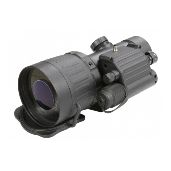
The Comanche 40 is mounted to a standard Weaver or Picatinny rail in front of an existing day scope; transforming it into a Night Vision Device (NVD) with no re-zeroing required. This NVCO can be used with day scopes of up to 12x magnification for optimal performance and is equipped with a quick release mount and remote control. - Page 7 The Comanche 40 is powered by a single Alkaline 1.5V AA or 3V CR123A Lithium battery. The mount system quick and reliable mounts the Comanche 40 to the Picatinny/Weaver rail. The Comanche 40 is shown in Figure 1-1. The ITEM NO. column in Table 1-1 indicates the number used to identify items in Figure 1-1.
-
Page 8: Standard Components
1.4 STANDARD COMPONENTS The Comanche 40 standard components are shown in Figure 1-2 and listed in Table 1-2. The ITEM column indicates the number used to identify items in Figure 1-2. FIGURE 1-2. STANDARD COMPONENTS TABLE 1-2. STANDARD COMPONENTS ITEM... -
Page 9: Optional Equipment
1.5 OPTIONAL EQUIPMENT The Comanche 40 optional equipment are shown in Figure 1-3 and listed in Table 1-3. The ITEM column indicates the number used to identify items in Figure 1-3. FIGURE 1-3. OPTIONAL EQUIPMENT TABLE 1-3. OPTIONAL EQUIPMENT ITEM DESCRIPTION PART NO. -
Page 10: Section 2. Operating Instructions
2. Install the battery (C) into the battery compartment (D), following the polarity order marked on the compartment for reference (E). 3. Replace the battery cap. CR123A BATTERY A A BATTERY FIGURE 2-1. COMANCHE 40 BATTERY INSTALLATION AGM Global Vision... - Page 11 Figure 2-2) and unlocking the cam lever (B). 4. Install the Comanche 40 on the Picatinny/ Weaver rail in front of the day scope so that the stop (C) slides into one of the rail’s transverse slots. The light suppressor should cover the day scope’s objective lens.
- Page 12 FIGURE 2-3. COMANCHE 40 ON A PICATINNY RAIL IN FRONT OF A DAY SCOPE Clamping Device Adjustment To adjust the mount’s clamping device, do the following: 1. Remove the Comanche 40 from the weapon. 2. With the clamping device unlocked, push the cam (D) towards the arrow, which will cause the nut (E) to slide out of its hole.
- Page 13 FIGURE 2-6. SIOUX850 IR ILLUMINATOR Use the optional Platform Ring to install the Sioux850 on the day scope. The Platform Ring with IR illuminator installed on a day scope is shown in Figure 2-7. FIGURE 2-7. SIOUX850 IR ILLUMINATOR Comanche 40 USER MANUAL...
-
Page 14: Controls And Indicators
2.2.1 COMANCHE 40 CONTROLS AND INDICATOR The Comanche 40 controls and indicator are shown in Figure 2-9 and defined in Table 2-1. The ITEM column indicates the number used to identify items in Figure 2-7. FIGURE 2-9. COMANCHE 40 CONTROLS AND INDICATOR... -
Page 15: Operating Procedures
2. Remove the objective lens cap and place it over the lens’ housing. 3. Verify that there are no bright light sources in the Comanche 40’s field of view. Turn the device on by rotation the operation switch to the ON position. After a slight delay, a green glow will appear in the day scope’s output lens. - Page 16 CAUTION: DO NOT store the equipment with the battery still in it. 8. Ensure that the Comanche 40 and any accessories are clean and dry before placing them into the storage case. 9. Place the Comanche 40 and any accessories into the storage case.
-
Page 17: Section 3. Maintenance
Comanche 40. Perform the tests, inspections, and corrective actions in the order listed in the table. This table cannot list all of the malfunctions that may occur with your Comanche 40, or all of the tests and corrective actions that may be necessary. If you experience an equipment malfunction that is not listed, or is not fixed by the corrective actions listed in the table, please contact Customer Service center. - Page 18 Customer Support. Light visible around light Incorrect position of the Reposition the Comanche 40 suppressor. Comanche 40 in relation to on the Picatinny/ Weaver rail. the day scope. Check the light suppressor If light suppressor is defective resilience.
-
Page 19: Section 4. Warranty Information
Customer. AGM Global Vision’s liability hereunder for damages, regardless of the form or action, shall not exceed the fees or other charges paid to AGM Global Vision by the customer or customer’s dealer. AGM Global Vision shall not, in any event, be liable for special,... -
Page 20: Product Registration
4.3 PRODUCT REGISTRATION In order to validate the warranty on your product, the customer must complete and submit AGM Global Vision PRODUCT REGISTRATION FORM on our website (www.agmglobalvision.com/ customer-support). 4.4 OBTAINING WARRANTY SERVICE To obtain warranty service on your unit, the End-user (Customer) must notify the AGM Global Vision service department via e-mail. -
Page 21: Section 5. Specifications
5 SPECIFICATIONS 5.1 SPECIFICATIONS The following tables provide information pertaining to the operational, optical, electrical, mechanical, and environmental characteristics of the Comanche 40 clip-on system. TABLE 5-1. OPTICAL DATA ITEM DATA Magnification Objective Lens Focal Length 80 mm Objective Lens F/number 1:1.44... - Page 22 -40 to +50°C (-40 to 122°F) Storage Temperature -50 to +50°C (-58 to 122°F) Natural night illumination Illumination Required (overcast starlight to moonlight) Environmental Rating Water and Fog-Resistant NOTE: All data are subject to change without notice. AGM Global Vision...
-
Page 23: Appendix
The PART NO. column indicates the primary number used by the manufacturer to identify an item; this number controls the design and characteristics of the item by means of its engineering, specifications, standards, and inspection requirements. FIGURE A-1. COMANCHE 40 SPARE PARTS TABLE A-1. COMANCHE 40 LIST OF SPARE PARTS ITEM DESCRIPTION PART NO. - Page 24 AGM Global Vision MAIN OFFICE 173 West Main Street PO Box 962 Springerville, AZ 85938 Tel. +1.928.333.4300 info@agmglobalvision.com www.agmglobalvision.com EUROPEAN OFFICE Andrey Lyapchev #7 Sofia, P.C. 1756 Bulgaria Tel. +44.292.255.0509 info@agmglobalvision.eu www.agmglobalvision.eu AGMglobalvision.com...
Need help?
Do you have a question about the COMANCHE 40 and is the answer not in the manual?
Questions and answers