
Related Manuals for Met One Instruments 034E


Summary of Contents for Met One Instruments 034E
- Page 1 034E WIND SENSOR OPERATION MANUAL Met One Instruments, Inc Corporate Sales & Service: 1600 NW Washington Blvd. Grants Pass, OR 97526 Tel (541) 471-7111 Fax (541) 471-7116 www.metone.com service@metone.com 034E-9800 REV A Page 1...
- Page 2 034E-9800 REV A Page 2...
-
Page 3: Copyright Notice
Copyright Notice © Copyright 2020 Met One Instruments, Inc. All Rights Reserved Worldwide. No part of this publication may be reproduced, transmitted, transcribed, stored in a retrieval system, or translated into any other language in any form by any means without the express written permission of Met One Instruments, Inc. -
Page 4: General Information
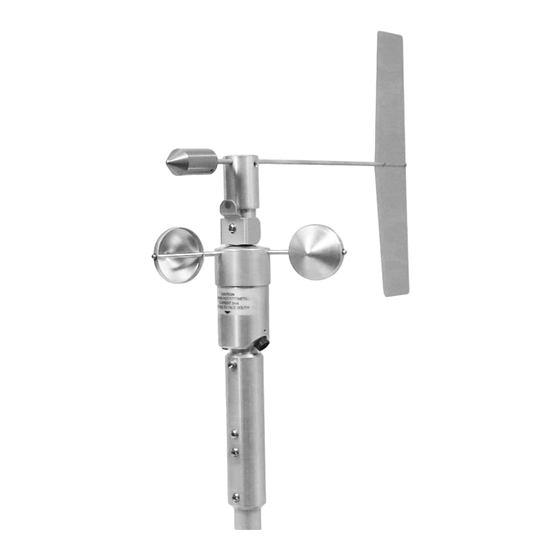
034E WIND SENSOR GENERAL INFORMATION The Met One Instruments Model 034E Wind Sensor consists of a wind speed sensor and wind direction sensor. The wind speed sensor uses a three cup anemometer to produce a series of contact closures in a magnetic reed switch. The frequency of the closures is proportional to wind speed. -
Page 5: Specifications
-50 Degrees C to +70 Degrees C, non-icing conditions Weight 2 lb. 9 oz. With cable Output signal Wind Speed Pulsed contact closure Maximum current 5mA Wind Direction Potentiometer output (0-10K ohms) Maximum current 10mA Maximum open circuit voltage 28 034E-9800 REV A Page 5... - Page 6 In addition, the shield on the signal cable leading to the translator must be connected to a good earth ground at the translator end. The cable route should not be vulnerable to lightning. 034E-9800 REV A Page 6...
- Page 7 RPM points. The vane and counterweight must both be removed for connection to the calibrator motor drive. The 034E wind sensor should be inspected periodically for physical damage to the vane assembly and cable connections. Inspect all vane assembly parts for security and damage.
- Page 8 TABLE 3-1 MODEL 034E WIND SPEED SENSOR CALIBRATION WIND VELOCITY VS OUTPUT FREQUENCY SPEED IN METERS PER SECOND V (mps) F Hz CALIBRATION 2.50 1.39 2.78 EQUATIONS 5.00 2.95 5.91 V mph = RPM +0.63 16.787 7.50 4.52 9.04 V mps = RPM +0.28...
- Page 9 53.55 119.77 66.67 2100.00 56.21 125.73 70.00 2200.00 58.87 131.68 73.34 2300.00 61.54 137.64 76.67 2400.00 64.20 143.60 80.00 2500.00 66.86 149.55 83.34 2600.00 69.53 155.51 86.67 2700.00 72.19 161.47 90.01 2800.00 74.85 167.43 93.34 034E-9800 REV A Page 9...
-
Page 10: Maintenance And Troubleshooting
No WD Sensor output Faulty pot assembly Replace pot assy. (REF 4.3) No WS Sensor output Faulty reed switch Replace reed switch (REF 4.4) No WS or WD output Faulty cable Check cable and connections 034E-9800 REV A Page 10... - Page 11 Gently pull the wires free from the terminal block and straighten them enough to allow easy passage through the stem on the top of sensor. Green J1-3 Black J1-4 White J1-5 034E-9800 REV A Page 11...
- Page 12 Refer to Figure 4-3. To facilitate maintenance and to minimize the risk of damage, support the sensor upright in the foam packing as shipped or some other method. FIGURE 4-3 Remove the alignment adaptor and screw if installed. 034E-9800 REV A Page 12...
- Page 13 Remove the wind direction vane if installed. Using a 5/64” allen wrench, loosen the center hub set screw 1 to 2 turns, and lift the vane up and off. 034E-9800 REV A Page 13...
- Page 14 The ¼ turn loosening will enable easier alignment of the pot/mount assembly during the re-assembly process. Carefully remove entire vane/potentiometer assembly from body of sensor. Use care to avoid snags when withdrawing the wires from the top stem. 034E-9800 REV A Page 14...
- Page 15 CAUTION: DO NOT LUBRICATE OR FORCE BEARINGS Install new bearings (Item 12) and cup assembly (Item 2) onto stem. NOTE: If potentiometer needs replacement, now refer to Section 4-3. NOTE: If reed switch needs replacement, now refer to Section 4-4. 034E-9800 REV A Page 15...
- Page 16 Prior to final closure of sensor body, inspect inside. Ensure that wires are routed as to prevent pinching or over-straining. Make sure wires do not get between spacer and interior of sensor body. Close sensor and secure with screw. Unit is now ready for service. 034E-9800 REV A Page 16...
- Page 17 3 and 5 (approx. 6k ohms). Remove shoulder screw. Rotate vane assembly clockwise ¼ turn as viewed from above. Check that the resistance between pins 3 and 4 is 8.5k ohms Unit is now ready for service. 034E-9800 REV A Page 17...
- Page 18 Using care to avoid stressing switch leads while routing, connect the switch wires in the terminal strip. Match wire colors with sensor connector harness. Refer to Figure 4-2. Follow steps J through O in Section 4.2. 034E-9800 REV A Page 18...
- Page 19 601580 SCREW, 6-32x5/8 PAN HD 601645 SET SCREW, 8-32 x 3/8, BRASS TIP 601650 SET SCREW, 8-32 x 3/16 10969 WD ALIGNMENT JIG, 034E 993000 ALLEN WRENCH 5/64 3368 SPACER, BRASS 601850 SCREW, 10/32 x 5/8 SOC CAP 034E-9800 REV A...
- Page 20 FIGURE 4-7 EXPLODED PARTS VIEW OF 034E 034E-9800 REV A Page 20...
- Page 21 Insert the vane tail shaft into the hub. Make sure the shaft is fully seated at the bottom of its hole. Rotate vane to align axis to sensor body and tighten set screw to secure vane assembly. 034E-9800 REV A Page 21...
- Page 22 This will prevent moisture from collecting in the screw holes during sensor operation. D. Tighten the set screws and recheck balance. Readjust as required and return the sensor to service. Loosen x2 Set Screws to adjust. Move counterweight left & right to balance. 034E-9800 REV A Page 22...
Need help?
Do you have a question about the 034E and is the answer not in the manual?
Questions and answers