Table of Contents
Advertisement
Quick Links
Advertisement
Table of Contents

Subscribe to Our Youtube Channel
Related Manuals for B+K precision 5492B


Summary of Contents for B+K precision 5492B
- Page 1 Model: 5492B, 5492BGPIB 5 ½ Bench Digital Multimeter USER MANUAL...
- Page 2 As described in the International Electrotechnical Commission (IEC) Standard IEC 664, digital multimeter measuring circuits (e.g., B&K Models 5492B) and the USB terminal are Installation Category II (CAT II). All other instruments’ signal terminals are Installation Category I and must not be connected to mains.
- Page 3 Do not install substitute parts or perform any unauthorized modifications to this instrument. Return the instrument to B&K Precision for service and repair to ensure that safety features are maintained. WARNINGS AND CAUTIONS WARNING and CAUTION statements, such as the following examples, denote a hazard and appear throughout this manual.
- Page 4 SAFETY SYMBOL This symbol serves as a warning to users of the input safety ratings. Refer to the operating instructions for details. Electrical Shock hazard. Chassis ground symbol. CAT I IEC Measurement Category I. Inputs may be connected to (1000V) mains (up to 300 VAC) under Category II overvoltage conditions.
-
Page 5: Table Of Contents
Table of Contents Chapter 1 General Information ..................... 9 1.1 Feature Overview ....................... 9 1.2 Input Power and Fuse Requirements ................. 9 Chapter 2 Overview ........................12 1.3 Package Contents ......................11 2.1 Front Panel Overview ....................... 12 2.2 Screen Display ......................... 14 2.3 Front Panel Menu Options .................... - Page 6 3.8.1 mX+b..........................32 3.8.2 Percent ..........................33 3.8.3 dB Calculation ........................34 Chapter 4 Measurement Options ....................37 3.8.4 dBm Calculation ........................ 35 4.1 Measurement configuration ....................37 4.1.1 Range ..........................37 4.1.2 Filter ..........................38 4.1.3 Relative ..........................39 4.1.4 Rate ..........................
- Page 7 5.3 GPIB Interface operation (model 5492BGPIB only) ............60 5.3.1 GPIB Connection ......................60 5.3.2 GPIB Interface Capability ....................61 5.3.3 GPIB Addressing ......................61 Chapter 6 SCPI Command Reference ..................62 5.4 Data Format ........................61 6.1 Command Structure ......................62 6.2 Command Syntax ......................
-
Page 8: Chapter 1 General Information
Input Power and Fuse Requirements The 5492B digital multimeter can operate on 110 V or 220 V with +/- 10% tolerance at 60 Hz or 50 Hz with +/- 5% tolerance respectively. Before powering the instrument, please check for correct power input setup that corresponds to the line voltage to be used for operation. - Page 9 General information Press both sides indicated by the arrows and pull to remove fuse box. Fuse Holder Voltage Indicator Window Fuse Box There is a second fuse with a fuse holder located in the front panel of the multimeter. This is an over current protection fuse for the low current measurement input.
-
Page 10: Front Panel Overview
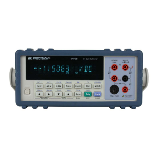
Rear Panel Summary Power up Front Panel Overview The front panel of the B&K 5492B is shown in Figure 2-1. This figure includes some important abbreviated information that should be reviewed before operating the instrument. Figure 1 - Front Panel View... - Page 11 Overview Measurement function keys Select measurement function: DC voltage and current, AC voltage and current, 2-wire and 4-wire resistance, frequency, period, continuity and diode test. Math function keys Select math function: mX+b, %, dB, dBm and Rel. Menu operation keys →...
-
Page 12: Screen Display
Overview Screen Display Figure 2-2 Display Annunciators * (asterisk) Instrument is ready to store readings (when in system menu) / Reading is being stored (when in measurement mode) (Diode) Instrument is in diode testing function (Speaker) Beeper on for continuity testing function Multimeter is in 4-wire resistance measurement mode. - Page 13 Overview 3. PERCENT Set the reference value for PERCENT function. 4. dB REF Set the dB reference voltage value. 5. dBm REF Set the dBm reference impedance value. 6. LIMIT TEST Enable or disable the limit testing. 7. HIGH LIMIT Set the high limit for limit testing.
-
Page 14: Front Panel Menu Overview
Overview Front Panel Menu Overview The menu is organized in a top-down tree structure with three levels (menus, submenus and parameters) as shown in Figure 2-3. You can use down ( ) or up ( ) keys to browse through the menu tree from one level to another. -
Page 15: Rear Panel Summary
“parameter” level, nothing will happen because it is at the lowest menu level. Rear Panel Summary The rear panel of BK 5492B is shown in Figure 2-4. This section includes important information that should be reviewed before operating the instrument. Figure 2-4 Rear Panel 1. - Page 16 Overview Table 2-2 Factory Default Settings Setting Factory Default Autozero Buffer No effect Continuity Beeper Digits 4 1/2 Rate Fast(0.1 PLC) 10 Ω Threshold Current(AC and DC) 5 1/2 Digits(AC) 5 1/2 Digits(DC) Filter Count Mode Moving average Range Auto Relative Value Rate(AC)
- Page 17 2.6.5 Warm-up time The 5492B is ready for use after power-up sequence (boot and self test) is completed. However, to achieve specified accuracy and stability, allow the instrument to warm up for half an hour. If the instrument has been subjected to extreme temperatures, allow additional time for internal temperature to...
-
Page 18: Chapter 3 Basic Measurements
Basic Measurements Chapter 3 Basic Measurements This chapter is outlined as follows: Overview Measuring Voltage Measuring Current Measuring Resistance Measuring Frequency and Period Measuring Continuity Testing Diode Math Functions Overview The front panel has two rows of keys to select various functions and operations. Most keys have a shifted function printed in blue above the key. - Page 19 Basic Measurements 5492B Digit Multimeter SENSE INPUT V Ω FAST SLOW DC Voltage 350V 1000V CATⅠ(1000V) ADRS HOLD TRIG AUTO FILT MATH SHIFT ! CATⅡ(300V) Source Period dB/m Ω POWER D C V AC V ¦ ¸ Fr eq C ont...
-
Page 20: Crest Factor
Basic Measurements 3.2.2 Crest factor AC voltage and current accuracies are affected by the crest factor of the waveform, the ratio of the peak value to the RMS value. Table 3-1 lists the fundamental frequencies at which the corresponding crest factor must be taken into account for accuracy calculations. -
Page 21: Front Panel Fuse Replacement
Basic Measurements 5492B Digit Multimeter INPUT SENSE Ω 4W V Ω FAST SLOW 350V 1000V CATⅠ(1000V) ADRS HOLD TRIG AUTO FILT MATH SHIFT ! CATⅡ(300V) CATⅡ(300V) Current Source Period Ω dB/m POWER D C V AC V ¦ ¸ Fr eq... -
Page 22: Connections
3.5.2 Gate Time Gate time is the amount of time the multimeter uses to sample frequency or period readings. For model 5492B, all RATE settings (Fast, Med and Slow) yield a gate time of one second. 3.5.3 Connections Assuming the multimeter is under factory default conditions, the basic procedure for measuring frequency or period is as follows: 1. -
Page 23: Measuring Continuity
Basic Measurements 5492B Digit Multimeter SENSE INPUT Ω 4W V Ω FAST SLOW AC Voltage 350V CATⅠ(1000V) 1000V ADRS HOLD TRIG AUTO FILT MATH SHIFT ! CATⅡ(300V) Source Period Ω dB/m POWER D C V AC V ¦ ¸ Fr eq... -
Page 24: Threshold Resistance Level
Basic Measurements 5492B Digit Multimeter SENSE INPUT Ω 4W V Ω FAST SLOW 350V 1000V ADRS HOLD TRIG AUTO FILT MATH SHIFT CATⅠ(1000V) ! CATⅡ(300V) Period Ω dB/m POWER Resistance D C V AC V ¦ ¸ Fr eq C ont... -
Page 25: Current Range
Basic Measurements 5492B Digit Multimeter SENSE INPUT Ω 4W V Ω FAST SLOW Diode 350V CATⅠ(1000V) 1000V ADRS HOLD TRIG AUTO FILT MATH SHIFT ! CATⅡ(300V) Period Ω dB/m POWER D C V AC V ¦ ¸ Fr eq C ont... -
Page 26: Math Functions
Basic Measurements Math Functions The multimeter math operations are divided into four categories: mX+b and percent dB and dBm calculations Statistics of buffered readings Limit testing The first two categories are discussed here in this section, while buffered reading statistics and reading limit testing are described in the next chapter, “Measurement Options”. -
Page 27: Percent
Basic Measurements increment or decrement the digits respectively. When the cursor position selects “ ”, the up and down arrow keys can be used to move the decimal place left or right of its current position. 4. Press (ENTER) to confirm the M value and the message “CHANGE SAVED” will be displayed for a moment and then multimeter returns back to the submenu level. -
Page 28: Db Calculation
“Reference”, displayed result will be positive. Contrarily, it will be negative if the value of “Input” is smaller than that of “Reference”. 3.8.3 dB Calculation The 5492B can express AC and DC voltages in dB units. The relationship between dB and voltage is dB = 20 log defined by the following equation: VREF... -
Page 29: Dbm Calculation
1 mW reference. With a user-programmable reference impedance, B&K 5492B reads 0 dBm when the voltage needed to dissipate 1mW through the reference impedance is applied. The relationship between dBm, reference impedance, and the voltage is defined... - Page 30 Basic Measurements 4. Press (ENTER) to confirm the reference value, and the message “CHANGE SAVED” will be displayed for a moment, then the multimeter will return to the submenu level. Press (ESC) to cancel the reference value input, and the multimeter will return back to the submenu level without changing the reference value.
-
Page 31: Measurement Configuration
Measurement Options Chapter 4 Measurement Options This chapter is outlined as follows: Measurement configuration Trigger Operations Buffer Operations Limit Operations System Operations Measurement configuration 4.1.1 Range You can let the multimeter automatically select the range using auto ranging or you can select a fixed range using manual ranging. -
Page 32: Filter
Measurement Options 4.1.2 Filter FILTER lets you set the filter response to stabilize noisy measurements. The multimeter uses a digital filter. The displayed, stored and transmitted readings are simply an average of a number of reading conversions (from 1 to 100). Perform the following steps to select a filter: →... -
Page 33: Relative
Measurement Options the oldest conversion is discarded, and the stack is re-averaged, yielding a new reading. See Figure 4-1 below. Repeat Average (REPEAT) For the repeating average filter, the stack is filled and the conversions are averaged to yield a reading. The stack is then cleared and the process starts over as shown in Figure 4-1. -
Page 34: Rate
Measurement Options displayed offset becomes the reference value. Subtracting the offset from the actual input, the display will be as follows: Displayed reading = Actual Input – Reference Selecting a range that cannot accommodate the relative value does not cause an overflow condition, but it also does not increase the maximum allowable input for that range. -
Page 35: Trigger Operations
Measurement Options Trigger Operations The multimeter’s triggering system allows you to generate triggers either manually, automatically, or externally for taking multiple readings per trigger. The following discusses front panel triggering, programmable trigger delay, and the reading hold feature. 4.2.1 Trigger Model The flowchart below (Figure 4-2) summarizes the triggering process of the instrument. - Page 36 Measurement Options 1. A bus trigger (*TRG) command is received via remote control. 2. The front panel key is pressed (The meter must be in local mode first). Trigger Source The trigger source can be set from the front panel trigger menu. Users can select either IMM, MAN, BUS, or EXT.
- Page 37 Measurement Options Table 4-1 Auto delay settings Function Range and Delay 120mV 1.2V 120V 1000V 120mV 1.2V 120V 750V 400ms 400ms 400ms 400ms 400ms 120mV 1.2V 120V 750V FREQ 12mA 120mA 1.2A 12mA 1.2A 400ms 400ms 400ms 120Ω 1.2kΩ 12kΩ 120kΩ...
-
Page 38: Enabling Limits
Measurement Options A 0.6kΩ reading becomes 600Ω (HI). When the reading is within the configured limit range specified by low and high limits, “IN” will be shown after measured display. If it is higher than the limit range, “HI” will be shown after the measured display. Similarly, if it is lower than the limit range, “LO”... -
Page 39: Configure Limit Beep
System Operations There are some system settings that can be configured on the 5492B multimeter, which include beeper control, saving and restoring instrument settings, front panel display control, key sound control, self-test,... -
Page 40: Beeper Control
4.5.2 Save Settings The 5492B allows user to save up to 10 instrument settings. These settings are saved as files in non-volatile memory (10 files: FILE-0 – FILE-9). Files will not be lost when the instrument is powered off. These settings can be restored at any time after power on. The settings that can be stored in each file are the same settings listed under the default settings. -
Page 41: Restore Settings
4.5.4 Display Control To speed up measurement rate for remote control, the 5492B allows the user to turn off the front panel display. When the front panel display is turned off, readings are not sent to the display. Some annunciators will still stay lid. -
Page 42: Key Sound
Measurement Options key to select ON or OFF for the front panel display. Press (ENTER) to confirm the selection. The message “CHANGE SAVED” will be displayed to show that the change is now in effect. → Press key to exit from the menu. 4.5.5 Key Sound The multimeter by default is shipped with beep sound enabled when keys are pressed. -
Page 43: Calibration
Measurement Options message, it will return to the parameter level for selecting self-test. If “BUILT-IN” is selected, the unit will run an internal self-test. This will take approximately 10-15 seconds. After completion, the message “TEST PASS” will display if no errors occur during the self-test. -
Page 44: Selecting An Interface
GPIB Interface operation Data Format The 5492B supports remote control over the USB (virtual com), RS-232, and GPIB interface located in the rear panel. You can use only one interface at a time. Standard Commands for Programmable Instruments (SCPI) is supported by these interfaces (unless otherwise noted), however they use different hardware configurations and communication protocols. - Page 45 Specifications Chapter 8 Specifications Technical Specifications Specifications Assumptions One year calibration cycle. Operating temperature between 18°C to 28°C Accuracy is expressed as: ±(% of reading + % of range ) after a 30 minute warm up and valid for 10 PLC (slow) ...
- Page 46 Specifications DC CHARACTERISTICS CONDITIONS: SLOW or MED with filter count of 10 DC Voltage Resolution, Full Scale reading and Accuracy ± (% of reading + % of range), 23 °C ± 5 °C Typical Accuracy Full Scale Rate Range Resolution Input (1 year) Reading...
- Page 47 Specifications DC Current Full Scale Accuracy Burden Voltage Rate Range Resolution Reading (1 year) & Shunt Resistor 0.1 μA <0.15 V / 10.1 Ω 12.0000mA 11.9999 0.05+0.008 1 μA <1.5 V / 10.1 Ω 120.000mA 119.999 0.05+0.004 Slow 10μA <0.3 V / 0.1 Ω 1.20000 A 1.19999 0.10+0.004...
- Page 48 Specifications 120.000 mV 1.50+0.200 0.50+0.200 0.10+0.200 0.30+0.300 1.0+0.300 1.20000 V 1.50+0.150 0.50+0.150 0.10+0.150 0.30+0.200 1.0+0.200 12.0000 V 1.50+0.150 0.50+0.150 0.10+0.150 0.30+0.200 1.0+0.200 120.000 V 1.50+0.150 0.50+0.150 0.10+0.150 0.30+0.200 1.0+0.200 750.00 V 1.50+0.150 0.50+0.150 0.10+0.150 0.30+0.200 1.0+0.200 120.00 mV 1.50+0.30 0.20+0.15 0.50+0.15 1.5+0.15 1.2000 V...
- Page 49 Specifications 12.0000 mA 1.0+0.150 0.50+0.150 0.25+0.150 2.0+0.150 1.20000 A 1.0+0.150 0.50+0.150 0.25+0.150 2.0+0.150 12.0000 A 1.0+0.150 0.50+0.150 0.25+0.150 2.0+0.150 12.000 mA 1.0+0.20 0.5+0.10 3.0+0.10 Fast 1.2000 A 1.0+0.20 0.5+0.10 3.0+0.10 12.000 A 1.0+0.20 0.5+0.10 3.0+0.10 Max. crest factor: 3.0 at full scale Specifications are for sine wave inputs >5% of the range Maximum Input and Overload Current Protection: 2A/ 250V fuse.
- Page 50 Specifications Maximum Input Protection: 1000VDC or 750VAC for all ranges. Open circuit voltage: Maximum voltage is 13.3 VDC for 120 Ω, 1.2 kΩ, 12 Ω, 12 MΩ and 120 MΩ ranges. Maximum voltage is 7 VDC for 120 kΩ and 1.2M ranges. Continuity Accuracy ±...
- Page 51 Specifications FREQUENCY AND PERIOD CHARACTERISTICS CONDITIONS: SLOW RATE (GATE TIME 1 Sec) Frequency Accuracy: ± (% of Reading) Input Frequency Gate Resolutio Full Scale Accuracy Sensitivity Range Range Time Reading (Sine Wave) 10 μHz 5 ~ 10 Hz 9.99999 0.05 200 mVrms 100 mV 100 μHz...
Need help?
Do you have a question about the 5492B and is the answer not in the manual?
Questions and answers