
Related Manuals for B+K precision 5490C Series


Summary of Contents for B+K precision 5490C Series
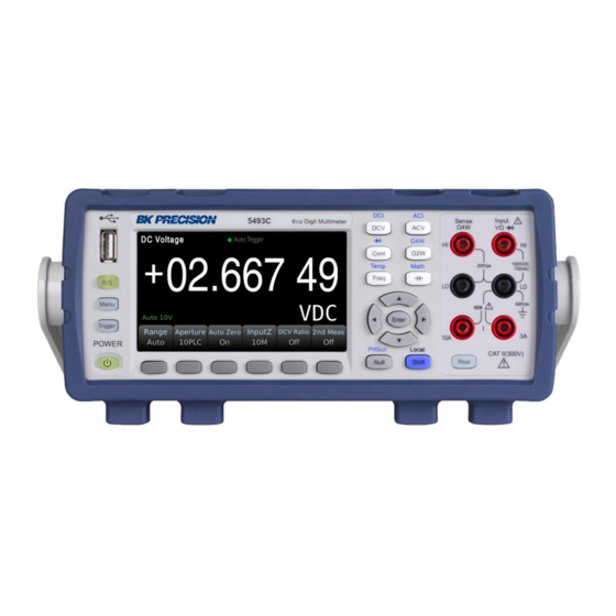
- Page 1 5490C Series 5 ½ and 6 ½ Digit Multimeters Models: 5492C/5492CGPIB, 5493C/5493CGPIB USER MANUAL...
- Page 2 Safety Summary The following safety precautions apply to both operating and maintenance personnel and must be followed during all phases of operation, service, and repair of this instrument. Before applying power to this instrument: Read and understand the safety and operational information in this manual. ...
- Page 3 Do not use this instrument in an electrical environment with a higher category rating than what is specified in this manual for this instrument. You must ensure that each accessory you use with this instrument has a category rating equal to or higher than the instrument's category rating to maintain the instrument's category rating.
- Page 4 finely-divided particulates. In relative humidity conditions outside the instrument's specifications. In environments where there is a danger of any liquid being spilled on the instrument or where any liquid can condense on the instrument. In air temperatures exceeding the specified operating temperatures. ...
- Page 5 Do not touch live circuits Instrument covers must not be removed by operating personnel. Component replacement and internal adjustments must be made by qualified service-trained maintenance personnel who are aware of the hazards involved when the instrument's covers and shields are removed. Under certain conditions, even with the power cord removed, dangerous voltages may exist when the covers are removed.
-
Page 6: Compliance Statements
Cooling fans This instrument contains one or more cooling fans. For continued safe operation of the instrument, the air inlet and exhaust openings for these fans must not be blocked nor must accumulated dust or other debris be allowed to reduce airflow. Maintain at least 25 mm clearance around the sides of the instrument that contain air inlet and exhaust ports. -
Page 7: Ce Declaration Of Conformity
CE Declaration of Conformity This instrument meets the requirements of 2014/35/EU Low Voltage Directive and 2014/30/EU Electromagnetic Compatibility Directive with the following standards. Low Voltage Directive EN 61010-1: 2010 EMC Directive EN 61326-1: 2013... -
Page 8: Safety Symbols
Safety Symbols Refer to the user manual for warning information to avoid hazard or personal injury and prevent damage to instrument. Electric Shock hazard This is the AC mains connect/disconnect mechanical power switch. On (Power). This is the In position of the power switch when instrument is ON. -
Page 9: Table Of Contents
Contents Safety Summary ............................... ii Compliance Statements ............................vi CE Declaration of Conformity ..........................vii Safety Symbols ..............................viii 1 General Information ...........................3 1.1 Operating Environment ............................. 3 1.2 Package Contents ............................... 3 1.3 Product Dimensions ............................4 1.4 Front Panel Overview ............................4 1.5 Rear Panel Overview ............................ - Page 10 Math Functions............................29 5.1 Null Operation ..............................29 5.2 Statistics ................................29 5.3 Limit ................................. 30 5.4 dB Calculation ..............................30 5.5 dBm Calculation ............................... 30 5.6 mX+b ................................30 5.7 Percent ................................30 Save / Recall ............................. 31 6.1 Save Readings ..............................31 6.2 Save Settings ..............................
-
Page 11: General Information
1 General Information The 5490C Series 5 ½ and 6 ½-digit benchtop multimeters offer a broad measurement range with speeds up to 1000 readings per second, and a basic DC Voltage accuracy up to 35 ppm delivering measurement results quickly and accurately. -
Page 12: Product Dimensions
1 x USB interface connection cable 1 x AC power cord 1 x T500 mAL fuse 1 x Test report 1 x Certificate of Calibration Verify that you have received all the items above when you get the multimeter. If anything is missing, please contact B&K Precision. -
Page 13: Rear Panel Overview
1.5 Rear Panel Overview Rear Panel Description Rear input terminals (6 ½-digit models only) Cooling fan GPIB interface (5492CGPIB/5493CGPIB models only) AC power input receptacle & fuse box External Trigger BNC connector LAN interface USB interface RS232 interface Chassis ground... -
Page 14: Getting Started
2.1 Input Power and Fuse Requirements The 5490C Series digital multimeters can operate on 110 V or 220 V with +/-10% tolerance at 60 Hz or 50 Hz. Before powering the instrument, please check for the correct power input setup that corresponds to the line voltage to be used for operation. -
Page 15: Check And/Or Change Fuse
2.2 Check and/or Change Fuse For safety, no power should be applied to the instrument while changing line voltage operation. Disconnect all cables connected to the instrument before proceeding. Check and/or Change Fuse Locate the fuse box next to the AC input connector in the rear panel Remove the fuse box as shown in Figure 2.2 –... -
Page 16: Carrying Handle Adjustment
There is a second fuse with a fuse holder located in the rear panel of the multimeter. This is an overcurrent protection fuse for the low current measurement input. It is a 5 x 20 mm 250 V, 3.15 A slow blow 50T glass fuse. -
Page 17: Front Panel Operation
Front Panel Operation This chapter covers available function settings and how to make basic measurements. 3.1 Front Panel Menu Reference Usage To configure the DC voltage measurement, including DC ratio measurement Range: 100mV, 1V, 10V, 100V, 1000V Range is set to Auto by default DCV(DCI) NPLC: {0.02, 0.2, 1, 10, 100} Default: 10 PLC Auto zero setting: OFF or ON (default: ON) - Page 18 NPLC: {0.02, 0.2, 1, 10, 100} Default: 10 PLC To configure the frequency and period measurements Freq (Temp) Filter: 3 Hz, 20 Hz, 200 Hz Gating time: 10ms, 100ms (default), 1s To configure the temperature test Probe type: two-wire test (default) or four-wire test Shift + Freq R0: resistance at 0 °C, default: 100 Ω...
-
Page 19: Display
3.2 Display The multimeters display can be set to number, bar meter, trend chart, or histogram. By default, the meter will be set to number display. 3.2.1 Change Display Mode To change the display mode, press Menu → Display → Display to access the display options. Use the softkey to select the desired display mode. -
Page 20: Display Label Text
Trend Chart The trend chart plots data as a trend line over time. The mode can be changed to display recent data where the time in seconds before present can be adjusted. Press the ‘Scale’ softkey to then select ‘Manual’ and use the directional keypad to adjust top/bottom boundaries. Histogram The histogram display mode groups data into bins represented graphically in vertical bars. -
Page 21: Digit Mask
3.2.3 Digit Mask The number of display digits can be changed manually. By default, the digit mask will change automatically based on other function settings and PLC settings. To change the digit mask press Menu → Display → Digit Mask. 3.2.4 Probe Hold Function The probe hold function records and displays up to 8 stable measurements adding them to an on- screen list. -
Page 22: Screen Capture And File Transfer
3.2.5 Screen Capture and File Transfer Press then press to save a screen capture to the multimeters internal memory as a .png file. Screen captures can be transferred from internal memory to a USB flash drive using the built-in file management system. Press Menu → Utility → Manage Files to access stored files. Use the directional keypad to highlight the file to be transferred then press Copy. - Page 23 Step 3: Range selection. Press Range and select the range. Auto range (Auto) can automatically select the appropriate range for measurement based on the input signal. The auto range is adjusted upwards to 120% of the existing range and down to 10% of the existing range. Step 4: Set the integration time.
-
Page 24: Dcv Ratio
Step 2: Turn on the DCV Ratio function. In DCV mode, enable DCV Ratio by pressing the softkey. 3.3.3 AC Voltage This section describes how to configure the 5490C Series for AC voltage measurements. In order to get the most accurate measurement, the corresponding RC time constant must be stable to 1/50 of the input AC signal level. - Page 25 Calculate the corresponding settling time using the RC time constant 0.22 s: settling time = ln(bias/settled value)*0.22 s settling time = ln(5 VDC / 2 VDC)*0.22 s settling time = 0.20 s The ACV function should be selected after the signal is connected to the digital multimeter's ACV input or when the signal has been connected, enough extra delay should be given to stabilize the signal.
-
Page 26: Dc Current
For example, if the input signal is 300 Hz, the stable data can be obtained using the 200 Hz filter. Step 5: Speed selection. Filter Slow Medium Fast √ ﹣ ﹣ 20Hz √ √ ﹣ 200Hz √ √ √ Each filter has a different test speed, choosing the right measurement speed based on the filter will result in more accurate test results and/or faster test speeds. -
Page 27: Ac Current
PLC (power-line cycles). 1PLC, 10PLC, 100PLC can inhibit the power supply noise. Selecting 100PLC can provide the best noise rejection, but at a slower rate. Step 5: Auto Zero. Auto-zeroing results in more accurate measurements but requires more test time. With auto zero enabled, the digital multimeter measures the offset once and subtracts the offset from all subsequently measured parameters. - Page 28 Step 3: Range adjustment Use the softkeys to select the range. Auto range (Auto) can automatically select the appropriate range for measurement based on the input signal. The auto range is adjusted upwards to 110% of the existing range and down to 10% of the existing range. Step 4: AC Filter Selection The instrument offers three filter options of 3Hz, 20Hz and 200Hz.
-
Page 29: Resistance 2W (2-Wire)
3.3.6 Resistance 2W (2-wire) Step 1: Configure the test leads as follows: Step 2: Press on the front panel to enter the two-wire resistance test interface. Step 3: Select the range. Press Range and select the range. Auto range (Auto) can automatically select the appropriate range for measurement based on the input signal. -
Page 30: Resistance 4W (4-Wire)
longer the integration time, the higher the accuracy but the slower the measurement. PLC (power-line cycle). 1PLC, 10PLC, 100PLC can inhibit the power supply noise. Selecting 100PLC can provide the best noise rejection, but at a slower rate. Step 5: Auto Zero. Auto-zeroing results in more accurate measurements but requires more test time. -
Page 31: Capacitance Measurement
Step 3: Select the range. Press Range and select the range. Auto range (Auto) can automatically select the appropriate range for measurement based on the input signal. The auto range is adjusted upwards to 110% of the existing range and down to 10% of the existing range. Step 4: Set the integration time. -
Page 32: Diode
Step 3: Select the range. Press Range and select the range. Auto range (Auto) can automatically select the appropriate range for measurement based on the input signal. The auto range is adjusted upwards to 110% of the existing range and down to 10% of the existing range. 3.3.9 Diode This section describes how to configure the diode test from the front panel. -
Page 33: Continuity
Step 2: Press then press on the front panel to enter the diode test interface. When converted to a 0.3V to 0.8V threshold, the instrument beeps (if a beep is enabled). A voltage of 0 to 5V is displayed on the front panel. When the measured break-over voltage is greater than 5V, the front panel will display OPEN. -
Page 34: Temperature Test
The continuity measurement behavior is as follows: ≤ 10 Ω Display the measured resistance and beeps (if the beeper is enabled). 10 Ω to 1.2 kΩ Display measured resistance, no buzzer. > 1.2 kΩ Display OPEN (ON), no buzzer. 3.3.11 Temperature test This section describes how to configure 2-wire and 4-wire temperature measurements from the front panel. -
Page 35: Frequency Measurement
Step 3: Press Probe to select the probe type. If you choose to use RTD, this menu will have a softkey to specify the resistance of the RTD at 0 degrees Celsius (R0). Step 4: Specify if you want to use Auto Zero. Auto-zeroing provides the most accurate measurements but takes more time to perform a zero measurement. - Page 36 Step 2: Press the button to enter the frequency measurement. Use the Type softkey to select frequency or period measurement. Freq is the frequency measurement and Period is the period measurement. Step 3: Range adjustment Press Range and select the range. Auto range (Auto) can automatically select the appropriate range for measurement based on the input signal.
-
Page 37: Secondary Measurement
Secondary Measurement Several measurement functions support secondary measurements. Secondary display measurements are only available when using Number or Bar Meter display modes only. Primary measurement function Available secondary measurement function(s) BeforeMath BeforeMath BeforeMath, Frequency BeforeMath, Frequency 2W, 4W Resistance Before math Frequency BeforeMath, AC Voltage, Period Temperature... -
Page 38: Limit
5.3 Limit The limit test allows the user to perform a Pass/Fail test. By setting the upper and lower limit values, the results will display the amount of Low and High failures. Use the softkeys to adjust Lower and Upper limits. Set the limits by using the cursor navigation keys and button. -
Page 39: Save / Recall
Save / Recall Measurement readings or instrument setting configurations can be saved into the instruments nonvolatile memory or a USB flash drive connected to the front panel USB host port. 6.1 Save Readings This function saves measurement data stored in the instrument buffer. Press Menu →... -
Page 40: Power On
6.4 Power On This function sets the instrument power on state which can be set to last, factory default, or a user defined state. Press Menu → Utility → Save / Recall to access the Power On settings. By default the power on state will be set to ‘Last’. -
Page 41: System Settings
System Settings 7.1 Set the language Press Menu → Utility → System → User Settings → Language to switch the language. The language can be set to English or Chinese. 7.2 Setting the date/time Press Menu → Utility → System → Date Time to set the date and time. Note: Setting the second is not supported using the front panel. -
Page 42: Interface
Data Carrier Detect Data Terminal Ready Transmitted the data Receive the data Grounding The RS232 interface on the 5490C Series uses a 9-pin DB9 connector. The pinouts are defined in the table below: Function Code Pin Connector Pin Number Transmitted Data... - Page 43 RS232 Connection Diagram Users can use the double-core shielded cable to make a three-wire connection cable (the length should be less than 1.5m). When making the connection cable, pins 4-> 6 and pins 7-> 8 should be shorted at the computer connector.
- Page 44 (4) Configure the serial communication Press Menu → Utility → I/O config to enter the port configuration interface. Select the RS232 option to configure RS232 communication. Select the Baudrate option to set the baud rate. Select Data bits to select the data bits. Parity: Select the check mode.
-
Page 45: Usb Interface
USB flash drive, the instrument is used as the host. 8.2.1 USB Device The 5490C Series can communicate with a PC through the USBTMC protocol. This multimeter uses a square type socket on the rear panel with the following pin sequence: This unit uses a USB-B type interface, which can communicate via a standard square USB interface cable. -
Page 46: Gpib Interface
Press Menu → Utility →I/O Config → LAN to Enter LAN Settings Screen. You can select Modify to change the settings or restore LAN settings to its default values. You can also turn ON or OFF the WLAN service. If turning on the WLAN, please insert the wireless network card first. Some LAN setup functions can only be performed through SCPI. - Page 47 GPIB System Interconnection for Double-piggyback Connector Method 2 of GPIB cable connection: GPIB System Interconnection for 3-piggyback Connector GPIB interface function This instrument provides most of the general functions of GPIB except the controller, see the following table: Code Function name Support all data source contact function Support all receiver contact function...
-
Page 48: Setting The Gpib Address
function Remote control / local function Device clear function Device trigger function No controller function Open collector drive 8.4.2 Setting the GPIB Address The instrument's GPIB is addressed in a single address mode with no secondary address; the default GPIB address is 8. Users can set their own GPIB address (0~30), and the address value can be automatically saved in non-volatile memory. -
Page 49: Specifications - 5492C / 5492Cgpib
Specifications - 5492C / 5492CGPIB... - Page 50 Specifications – 5492C / 5492CGPIB...
-
Page 51: Specifications - 5493C / 5493Cgpib
Specifications - 5493C / 5493CGPIB... - Page 52 Specifications – 5493C / 5493CGPIB...
- Page 53 Specifications – 5493C / 5493CGPIB...
-
Page 54: Supplementary Specifications - 5493C / 5493Cgpib
10.1 Supplementary specifications – 5493C / 5493CGPIB Display readings and measuring speed DC resistance, DC voltage, DC current Integration time Digits Readings/second Noise error 6 1 2 ⁄ 100PLC/2s(1.67s) 0.5(0.6) 6 1 2 ⁄ 10PLC/200ms(167ms) 5(6) 5 1 2 ⁄ 1PLC/20ms(16.7ms) 45(55) 0.001% range... -
Page 55: Service Information
Service Information Warranty Service: Please go to the support and service section on our website at www.bkprecision.com to obtain a RMA #. Return the product in the original packaging with proof of purchase to the address below. Clearly state on the RMA the performance problem and return any leads, probes, connectors and accessories that you are using with the device. - Page 56 LIMITED THREE YEAR WARRANTY B&K Precision Corp. warrants to the original purchaser that its products and the component parts thereof, will be free from defects in workmanship and materials for a period of three years from date of purchase. B&K Precision Corp. will, without charge, repair or replace, at its option, defective product or component parts.
- Page 57 22820 Savi Ranch Parkway Yorba Linda, CA 92887 www.bkprecision.com © 2020 B&K Precision Corp. V09212020...
Need help?
Do you have a question about the 5490C Series and is the answer not in the manual?
Questions and answers