Advertisement
2006-08
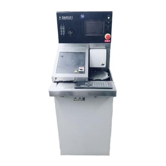
DATA MAINTENANCE MANUAL
Automatic Dicing/Cutting Saws
UHESDE*054C
DAD321
DAC351
DAD361
DAD341
DAD381
SOFTWARE VERSION 5.4 SERIES
Copyright of this document is owned by Disco Corporation ("Disco").
No part of this document may be copied or reproduced in any form
or by any means, without the express written permission of Disco.
Also, this document may not be disclosed or transferred to third
parties.
This document is printed on recyclable Lint-Free paper.
- The blue paper is recyclable as used paper just like plain paper.
- The cover paper and adhesive portions are non-recyclable.
(Remove the cover and adhesive portions before recycling.
Recycle the blue paper only.)
Advertisement
Table of Contents


Need help?
Do you have a question about the DAD321 and is the answer not in the manual?
Questions and answers