Table of Contents
Advertisement
Quick Links
Purpose:
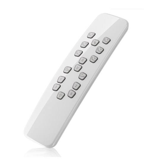
Quick technical description of the HC20 PCBA used in HC20 and HBBRIO RF handsets
Overview:
The PCBA is divided into the following sub circuits:
Ref:
Circuit diagram for HC20 board – 10907483-C.
Block Diagram
Technical description for
HC20 schematic
Side 1/7
Rev. A
Date:
2014-09-26
Init: TOP
Advertisement
Table of Contents

Summary of Contents for Linak HC20 PCBA
- Page 1 Date: HC20 schematic 2014-09-26 Init: TOP Purpose: Quick technical description of the HC20 PCBA used in HC20 and HBBRIO RF handsets Overview: The PCBA is divided into the following sub circuits: 1) Battery connection 2) Micro controller 3) RF transmitter + antenna...
- Page 2 Rev. A Technical description for Date: HC20 schematic 2014-09-26 Init: TOP Sub circuit description Battery connection 4 x AAA (LR03) batteries are connected in series to S24(+) and S19(-). Q1, Z2 and R8 work as a protection against wrong polarization. The MCP1702T step down the input voltage to 3.3VDC.
- Page 3 Rev. A Technical description for Date: HC20 schematic 2014-09-26 Init: TOP Micro controller The uC handles all key scan, Backlight and LED operation and of cause setup and data stream to the RF transmitter. When the handset is not used, the microcontroller (uC) enters a low-power mode where all external clock frequencies are switched off.
- Page 4 Rev. A Technical description for Date: HC20 schematic 2014-09-26 Init: TOP RF transmitter+antenna The RF transmitter is actually a SI4010 but preloaded with a specific supplier software and therefor named SI4012. The modulation scheme is the simplest form of ASK modulation called OOK. The data bit rate is 4 kbit/s (each bit having a length of 250 us).
- Page 5 Rev. A Technical description for Date: HC20 schematic 2014-09-26 Init: TOP Key-matrix The key-matrix (example above) detects if a key is pressed. The uC has KOUTx set to 0. In turn it threstates KINx and listen. KINx is per default “HIGH” (above 0.7xVcc). If KINx is detected as being less than 0.3xVcc it measures KOUTx and thus detects which key is pressed.
- Page 6 Rev. A Technical description for Date: HC20 schematic 2014-09-26 Init: TOP Backlight The backlight is controlled by the microcontroller (uC). When the backlight is turned off the LED_PWM is high and because of the capacitor C13 the gate on Q9 will be pulled down by R9. A voltage of 6V will be on the diodes.
- Page 7 Rev. A Technical description for Date: HC20 schematic 2014-09-26 Init: TOP The circuitry for the torch/transmit indicatior LED is a constant current generator. It is controlled by the u-controller that generates a 100kHz PWM signal with 50% duty-cycle. The LED is turned on ether when the handset is transmitting (HBBRIO) or when a specific button is pressed (HC20).


Need help?
Do you have a question about the HC20 PCBA and is the answer not in the manual?
Questions and answers