Table of Contents
Advertisement
Quick Links
M-Kits include everything required to convert an existing RG-03 to a RG-03M System, except for some basic hand tools and a
soldering iron and solder. Please read these instructions through before beginning the conversion.
Starting Installation
1) Slack off the strings, remove them from the tailpiece and tape them away
from the cover plate. Remove the cover plate screws and set the cover plate
aside. Remove the tailpiece and resonator cone complete with the spider bridge.
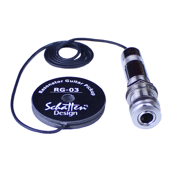
RG-03
The RG-03 was supplied with an endpin jack. Adding the M microphone to
the second channel of the output is quite straight forward.
1) Remove the jack from the instrument.
2) Unscrew the jack cover and insert the bare end of the mic cable through the
hole in the cover.
3) The mic cable is a shielded 2 conductor cable. It is necessary to strip the
outer black insulation from the other end of the cable.
4) Strip about 3/4" of the black insulation, exposing the ground (-) shield wrap.
Twist the wrap to form a single lead and tin it.
5) The inner insulated (+) wire is now exposed. Strip it back about one-quarter inch and tin it.
6) Pry open the two teeth on the cable clamp that are holding the pickup lead wire in place.
7) Solder the mic cable (+) to the lug as shown.
8) Solder the ground (-) to the cable clamp as shown.
9) Bend the teeth of the cable clamp back down around the 2 lead wires and screw the jack cover back in place.
10) Reinstall the jack on the instrument.
11) Continue the installation as detailed in the RG-03M installation instructions.
RG-03 Std
The RG-03 Std was supplied with a black ABS jack assembly with a 1/4" jack
inside
1) Remove the jack assembly from the instrument.
2) Remove the two screws holding the cover on the jack body.
3) Remove the nut and washers that are holding the black jack in place. Note that
the contact closest to the bottom of the jack box is bent upwards slightly so that it
won't come into contact with the ground shield coating of the box.
4) Drill a second 5/32" hole through the top in the area under the tailpiece. Take an
old guitar string and insert it down through the hole in the top. Tape the end of the
mic lead wire to the string and pull it back through the hole.
5) Remove the jack from the jack assembly box and clip the wires soldered to jack
as close to the jack as possible. Slide the pickup lead wire out of the jack assembly
box and remove the small rubber grommet from the box.
a) Insert the pickup lead wire back into the box.
b) Strip about 3/4" of the black insulation, exposing the ground (-) shield wrap. Twist the wrap to form a single lead
and tin it.
c) The inner insulated (+) wire is now exposed. Strip it back about one-quarter inch and tin it. Solder the inner lead
(+) from the pickup to the new jack as shown.
d) Solder the ground shield from the pickup to the new jack as shown.
d) The mic cable is a shielded 2 conductor cable. Insert the mic cable through the same hole in the box wall that the
pickup goes through. It is necessary to strip the outer black insulation from the bare end of the cable. Strip about 3/4" of the
black insulation, exposing the ground (-) shield wrap. Twist the wrap to form a single lead and tin it.
e) The inner insulated (+) wire is now exposed. Strip it back about one-quarter inch and tin it.
f) Solder the (+) mic lead to the jack as shown. Solder the mic outer shield (-) ground to the jack as shown.
g) Reinstall the jack back into the box with the lug for the pickup closest to the bottom of the box. Make sure that the
solder lug is bent up slightly so that it cannot come into contact with the ground shield coating of the box.
h) Put the cover back on the jack assembly and reinstall it on the instrument.
i) Continue installation as detailed in the RG-03M installation instructions.
RG-03 M-Kit Jack Change Instructions
Advertisement
Table of Contents

Related Manuals for Schatten Design RG-03


Summary of Contents for Schatten Design RG-03
- Page 1 RG-03 M-Kit Jack Change Instructions M-Kits include everything required to convert an existing RG-03 to a RG-03M System, except for some basic hand tools and a soldering iron and solder. Please read these instructions through before beginning the conversion. Starting Installation 1) Slack off the strings, remove them from the tailpiece and tape them away from the cover plate.
- Page 2 RG-03 Pro The RG-03 Pro was supplied with a black ABS jack body with a volume control and black 1/4" jack. Note: The Mini Pre 2 has volume controls for the microphone as well as for the pickup. You have a choice as to whether you want to continue to use the volume control on the jack assembly or not.
- Page 3 The M microphone in the RG-03M system was designed to add air, clarity and sound quality to the normal attributes of the RG-03 pickup sensor. The M microphone was not designed to be, nor is it intended to be used as a stand-alone microphone.
- Page 4 ) Place the small length of rubber tubing over the already installed cone mounting screw. Slide the tubing down as close to the cone as you can. The tubing has two functions: it acts as a damper and it isolates the pickup from coming into contact with the mounting screw.
- Page 5 For hanging jack use 1) Drill two holes 5/32" (0.070") in diameter on the face of the instrument directly under the tailpiece. The holes should be placed about 1 ½" from the end of the guitar so that it misses the end block. 2) Unsolder the pickup and mic lead wiring from the endpin jack and clip the ends of the wires clean.
- Page 6 We warrant to the original purchaser that our pickups are free from defects in materials and workmanship for a period of 2 (two) years. Should a product fail to perform properly within the specified warranty period you may contact your dealer or Schatten Design for instructions.
Need help?
Do you have a question about the RG-03 and is the answer not in the manual?
Questions and answers