
Related Manuals for Epiroc SB Series


Summary of Contents for Epiroc SB Series
- Page 1 702, 1102 Safety and operating instructions Hydraulic breakers © Construction Tools PC AB | 9800 1273 01 | 2020-04-03 Original Instructions...
-
Page 3: Table Of Contents
Contents Table of Contents 1 Introduction .......................... 6 About the Safety and operating instructions .................... 6 2 Safety instructions........................ 6 Safety signal words ............................ 6 Personal precautions and qualifications ...................... 6 2.2.1 Transport ................................ 6 2.2.2 Installation, storage, maintenance and disposal.................... 6 2.2.3 Operation................................ 6 2.2.4 Testing................................ 7 2.2.5 Personal protective equipment .......................... - Page 4 Contents Operating ................................ 18 6.2.1 Risk area ................................. 18 6.2.2 Breaking ................................ 18 6.2.3 Breaking under water ............................ 20 6.2.4 Special applications............................ 20 7 Maintenance .......................... 20 Cleaning ................................ 21 Every second hour............................ 21 7.2.1 Lubricating with a grease gun.......................... 21 7.2.2 Automatic lubrication ............................ 21 Every day ................................ 21 7.3.1 Change wear plate and bolts...........................
- Page 5 Contents © Construction Tools PC AB | 9800 1273 01 | 2020-04-03 Original Instructions...
-
Page 6: Introduction
DANGER Indicates a hazardous situation which, if not avoided, will result in death or serious injury. Epiroc is a leading productivity partner for the mining, in- frastructure and natural resources industries. With cut- WARNING Indicates a hazardous situation which, if not avoided, could result in ting-edge technology, Epiroc develops and produces in- death or serious injury. -
Page 7: Testing
Safety and operating instructions 2.2.4 Testing 2.4 Installation, precautions Testing of the hydraulic installation must only be carried out by professional technicians. The technicians must be 2.4.1 Hydraulic system authorised to approve a hydraulic installation in accor- dance with national directives. DANGER Compressed gas, explosion hazard The integrated piston accumulator is pressurized even 2.2.5 Personal protective equipment... -
Page 8: Assembly Or Disassembly
Safety and operating instructions Dust and fumes in the air can be invisible to the naked 2.4.2 Assembly or disassembly eye, so do not rely on eye sight to determine if there is WARNING Moving parts dust or fumes in the air. Risk for leaking oil and personal injury, such as crushed To reduce the risk of exposure to dust and fumes, do all hands and fingers. -
Page 9: Maintenance, Precautions
Safety and operating instructions safety regulations and recommendations. Consult WARNING Noise hazard with physicians experienced with relevant occupa- High noise levels can cause permanent and disabling tional medicine. hearing loss and other problems such as tinnitus (ring- u Work with your employer and trade organization to ing, buzzing, whistling, or humming in the ears). -
Page 10: Storage, Precautions
Safety and operating instructions WARNING Hot working tool The tip of the working tool gets very hot during opera- tion. Touching it may lead to burns. u Never touch the hot working tool. u If you have to carry out any activities, wait for the working tool to cool down first. -
Page 11: Overview
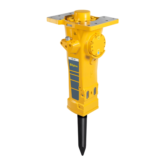
Safety and operating instructions 3.2 Main parts 3 Overview To reduce the risk of serious injury or death to your- self or others, read the Safety instructions section found on the previous pages of this manual before operating the machine. 3.1 Design and function SB is a range of rig mounted hydraulic breakers de- signed for all kinds of demolition works. -
Page 12: Labels
Safety and operating instructions 3.3.3 Labels on the accumulator 3.3 Labels The machine is fitted with labels containing important in- formation about personal safety and machine mainte- nance. The labels must be in such condition that they are easy to read. New labels can be ordered from the spare parts list. -
Page 13: Transport
Safety and operating instructions 4 Transport 5 Installation Before installing the hydraulic breaker on the carrier or WARNING Falling hydraulic breaker operating it, read the operation manual and safety in- If the hydraulic breaker is tipping over and falling, it may structions provided by the carrier manufacturer. -
Page 14: Hydraulic Oil
Safety and operating instructions NOTICE Always use clean oil and filling equipment. Hose connections Left (As seen from operator's seat) 5.3 Assembly Water Pressure to Pressure breaker for Con- Circulate the hydraulic oil before connecting the ma- tiLube II mi- chine. - Page 15 Safety and operating instructions 2. Place NYLOK BLUE PATCH™ (Known as TUF-LOK ® in Europe) screws through all bore holes and fit nuts to the screws. ® If NYLOK BLUE PATCH™ (Known as TUF-LOK Europe) screws are not available we recommend us- ®...
-
Page 16: Pressure Adjustment
Safety and operating instructions 6. After mounting the breaker, carefully extend and re- Position the hydraulic breaker vertically towards solid tract the bucket cylinder to its full extent in each di- bedrock or similar to adjust the pressure using a pres- rection. -
Page 17: Changing The Working Tool
Safety and operating instructions 5.6.1.3 Blunt tool • Very good energy ap- plication • Optimum breaking ef- fect • No torsion effect 5.6.2 Changing the working tool WARNING Running engine Changing the inserted tool or accessories while the car- NOTICE The lock buffer in the tool retainer lock is rier's engine is running can cause serious injury. -
Page 18: Operation
Safety and operating instructions 6.2 Operating 6.2.1 Risk area Before starting the hydraulic breaker, make sure that no persons are in the risk area, 20 meters (66 ft) both hori- zontally and vertically from the hydraulic breaker. 20 m 6 Operation 6.2.2 Breaking NOTICE The hydraulic breaker or the working tool is not to be used as a lifting device. - Page 19 Safety and operating instructions n Start near the edge and work your way in towards the middle. Never start in the middle of large objects. n Never run the hydraulic breaker longer than 15 sec- onds on the same spot. Move the working tool to a new position if the object does not break.
-
Page 20: Breaking Under Water
Safety and operating instructions 1.5-2 NOTICE When operating under water the hydraulic breaker must be fed with compressed air to keep the area between the piston and the inserted tool free from water. If the area between the piston and the inserted tool gets filled with water, it may penetrate into the hy- n Never use the hydraulic breaker as a sledge hammer draulic oil system when the hydraulic breaker is started. -
Page 21: Cleaning
Collect the water used for cleaning if it has been con- and run. To avoid this always use Epiroc chisel paste. taminated by hydraulic oil and chisel paste. u Dispose of the water in accordance with the applica- ble regulations to avoid environmental hazards. -
Page 22: Wear Limits
Safety and operating instructions The wear bushings must be replaced when the inner 7.4.2 Changing the lower bushing diameter (A) has reached its maximum wear limit, NOTICE The upper bushing and stop ring must be re- see section "Wear limits" and "Changing the lower placed in a workshop. -
Page 23: Every Year
Safety and operating instructions 4. Carefully clean the bore and the lower bushing seat Before a used machine is scrapped it must be emptied area. and cleaned from all hydraulic oil. The remaining hy- draulic oil must be deposited and any negative influence 5. -
Page 24: Troubleshooting
Safety and operating instructions 10 Troubleshooting 10.1 Hydraulic breaker does not start Cause Remedy Pressure and tank hoses are Check that the connections of the pressure and tank Carrier driver mixed up. hoses are correct.See section "Hoses and connection". Shut off valve in pressure and/or Check the shut off valve and open it. -
Page 25: Operating Temperature Too High
Safety and operating instructions Cause Remedy Working tool jams in the lower Correct the direction of the carrier boom. The pressing Carrier driver breaker part. force must act in the axial direction of the hydraulic breaker. Check the shaft of the working tool and deburr if required. Use the right type, and amount of grease. -
Page 26: Technical Data
Safety and operating instructions 11 Technical data 11.1 Machine data SB 702 SB 1102 Part number 8460 0300 85 8460 0300 90 Service weight, kg (lb) 720 (1600) 1060 (2300) Delivery weight, kg (lb) 521 (1149) 789 (1739) Suitable carrier weight class, t (lbs) 10-17 (22000-37500) 13-24 (29000-53000) Working length of working tool in standard version, mm (in.) -
Page 27: Noise Declaration Statement
Safety and operating instructions 11.3 Noise declaration statement SB 702 SB 1102 Sound pressure dB(A) Sound power dB(A) Sound pressure level according to EN ISO 3744 in accordance with directive 2000/14/EC at 10 metres distance. Guaranteed sound power according to EN ISO 3744 in accordance with directive 2000/14/EC inclusive spread in pro- duction. -
Page 28: Flow Diagrams For The Correct Operating Pressure
Safety and operating instructions 11.4 Flow diagrams for the correct operating pressure The carrier’s oil flow can be restricted to achieve the right operating pressure. Restrictors can be ordered from the spare parts list. The diagram shows oil flow at viscosity 32 cSt. 11.4.1 SB 702: 120-170 bar (1740-2466 psi) Ø... -
Page 29: Sb 1102: 130-180 Bar (1886-2611 Psi)
Safety and operating instructions 11.4.2 SB 1102: 130-180 bar (1886-2611 psi) Ø 8.9 mm Ø 7.3 mm Ø 8.4 mm l/min © Construction Tools PC AB | 9800 1273 01 | 2020-04-03 Original Instructions... -
Page 30: Ec Declaration Of Conformity
Safety and operating instructions 12 EC Declaration of Conformity 12.1 EC Declaration of Conformity (EC Directive 2006/42/EC) We, Construction Tools PC AB, hereby declare that the machines listed below conform to the provisions of EC Directive 2006/42/EC (Machinery Directive) and 2000/14/EC (Noise Directive). Hydraulic breaker Guaranteed sound Measured sound... - Page 32 Any unauthorized use or copying of the contents or any part thereof is prohibited. This applies in particular to trademarks, model denominations, part numbers, and drawings. epiroc.com...
Need help?
Do you have a question about the SB Series and is the answer not in the manual?
Questions and answers