Table of Contents
Advertisement
Quick Links
STATE OF CALIFORNIA
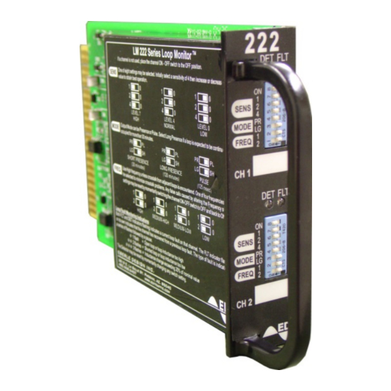
MODEL 222
INDUCTIVE LOOP DETECTOR
SENSOR UNIT
THE MODEL 222 SERIES INDUCTIVE LOOP DETECTOR SENSOR UNIT IS DESIGNED AND
MANUFACTURED IN THE USA BY EBERLE DESIGN INC., PHOENIX, ARIZONA,
AN ISO 9001:2008 REGISTERED COMPANY.
U.S. PATENT NO. 7,855,893.
© COPYRIGHT 2015 EDI
SERIAL NUMBER: 1506XXXXX and up
PCB Issue B, 010-6222-001
REVISION: JUNE 2015
pn 888-0222-002
Advertisement
Table of Contents

Subscribe to Our Youtube Channel
Related Manuals for EDI 222 Series

Summary of Contents for EDI 222 Series
- Page 1 STATE OF CALIFORNIA MODEL 222 INDUCTIVE LOOP DETECTOR SENSOR UNIT THE MODEL 222 SERIES INDUCTIVE LOOP DETECTOR SENSOR UNIT IS DESIGNED AND MANUFACTURED IN THE USA BY EBERLE DESIGN INC., PHOENIX, ARIZONA, AN ISO 9001:2008 REGISTERED COMPANY. U.S. PATENT NO. 7,855,893.
-
Page 2: Table Of Contents
Table of Contents 1.1 Glossary .......................... 1 1.2 General Description ......................1 1.3 General Characteristics ....................2 1.4 Installation and Adjustments .................... 2 1.5 Loop Installation ....................... 3 1.6 Theory of Operation ......................4 1.6.1 System Description ....................4 1.6.2 Description of Circuit Operation ................5 1.7 Maintenance ........................ -
Page 3: Glossary
Model 222 Operations Manual 1.1 GLOSSARY A - Ampere C - Celsius Component - Any electrical or electronic device Crosstalk – a symptom of interference between two adjacent loops running at similar frequencies ∆L/L – Change of inductance divided by the nominal inductance DC - Direct Current DIP –... -
Page 4: General Characteristics
Model 222 Operations Manual 1.3 GENERAL CHARACTERISTICS Each channel of the Model 222 will tune automatically to any loop and lead-in inductance between 20 and 2000 microhenries and will provide satisfactory operation with lead-ins up to 1000 feet in length. The unit will detect inductance changes as small as 0.01% ∆L/L. -
Page 5: Loop Installation
Model 222 Operations Manual HIGH (0). Four frequency positions are available on each channel to assist in alleviating interference affecting more than two units. Frequency FREQ 1 FREQ 0 High Med. High Med. Low e. If a channel is not to be used, it may be switched off (disabled) by setting the top DIP switch (switch 8) away from the ON setting. -
Page 6: Theory Of Operation
Model 222 Operations Manual shield may be connected to earth at the cabinet end but should then be insulated and isolated from earth ground at the loop end. Make sure that the loop wire is pushed fully to the bottom of the saw slot. Small pieces of foam rubber or similar material may be used at various points around the circumference to prevent the loop wire from rising up while the sealant is poured. -
Page 7: Description Of Circuit Operation
Model 222 Operations Manual The microcontroller checks the sample to confirm that it is still within acceptable operating limits and then determines whether the sample has changed sufficiently with respect to the stored reference to indicate the presence of a vehicle. It then controls the output and indicator appropriately. Small changes in period which occur over a relatively long time are considered due to the environment and are tracked out by altering the stored reference. -
Page 8: Maintenance
Model 222 Operations Manual Front panel switch settings are read directly by the microcontroller parallel ports P3 and P4. The Call Output opto-isolator U1 (U2) is driven directly by the microcontroller port P1_2 (P1_3). The front panel LED indicators DS1 (DS2) are similarly driven by the microcontroller port P5. Monolithic regulator VR1 provides a stable 5 volt DC power supply to the digital circuitry and loop oscillators. -
Page 9: Trouble Shooting Sequence Chart
Model 222 Operations Manual 1.7.2 TROUBLE SHOOTING SEQUENCE CHART. Apply 24 VDC power to the unit (pin J1-B) referenced to Logic Ground (pin J1-A). Connect 100 microhenry inductors to the loop inputs pins J1-D (J1-J) and J1-E (J1-K) to simulate the connection of loops. -
Page 10: Specifications
Model 222 Operations Manual 1.8 SPECIFICATIONS Power Supply: 24 VDC, 80mA maximum, 40mA quiescent. Loop Input: The loop inputs incorporate transient protection devices and the loop oscillator circuitry is transformer isolated. The transient protection will withstand the discharge of a 10uF capacitor charged to 2,000V across the loop inputs or between any loop input and earth ground. - Page 11 Model 222 Operations Manual Each channel is fitted with a high intensity RED detect LED indicator (DET) and a Yellow Fault LED indicator (FLT). Front Panel Controls: Front panel mounted DIP switches allow the user to set up sensitivity, operational mode, frequency and channel OFF/ ON state independently for each channel.
-
Page 12: Mechanical
Model 222 Operations Manual 1.8.1 MECHANICAL Height ........................4.50 inches Width ........................1.12 inches Depth (excluding handle) ..................6.875 inches 1.8.2 ENVIRONMENTAL Storage Temperature Range ................-45 to +85 Operating Temperature Range ................. -34 to +74 Humidity Range (non-condensing) ............. 0 to 95% Relative 1.8.3 ELECTRICAL DC Supply Voltage Minimum .................. -
Page 13: Parts List And Schematic
Model 222 Operations Manual 1.9 PARTS LIST AND SCHEMATIC |------------------------------------------------------------------------------------------------------------------| |Bill Of Materials for LM222 Production Issue B Rev D.sch |------------------------------------------------------------------------------------------------------------------| |Item|EDI Part Number|Qty|Description |Reference |Manufacturer |----+---------------+---+-------------------------------------------------+-------------------+-------------------| |(NO COMPONENT) |10 |(NO COMPONENT) |ENABLE1-2 GND |M1-2 |255-0000-S |RESISTOR, 1/8W, 0 OHMS, 5%, 1206 surface mount... - Page 14 Model 222 Operations Manual |430-7313-S |Transistor, Dual N Channel FET, IRF7313, SO8 |Q7 Q10 Q12 |440-1002-S |GAS DISCHARGE TUBE |CR5-6 |LITTLEFUSE |SL1002A090SM |440-7805-S |MC7805BD2T, 5V REG., 1A, D2PAK |VR1 |MOTOROLA |485-7643-S |MICROCONTROLLER, CY8C27643-24PVI |CYPRESS |490-1000-S |IC, 74VHC00, QUAD 2-INPUT NAND GATE, SO14 |FAIRCHILD |520-0102-P |Connector, Header, 2 Pin...
- Page 15 Model 222 Operations Manual Eberle Design Inc. Page 13...
- Page 16 Model 222 Operations Manual Eberle Design Inc. Page 14...
- Page 17 Model 222 Operations Manual Eberle Design Inc. Page 15...
Need help?
Do you have a question about the 222 Series and is the answer not in the manual?
Questions and answers