Table of Contents
Advertisement
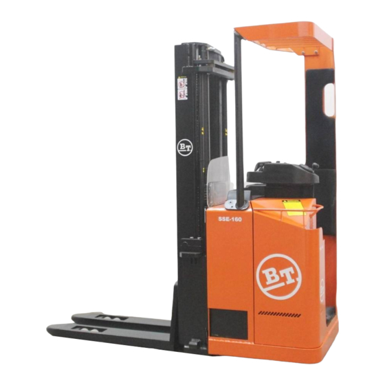
Operator's Manual
SSE135/SSE160
Valid from serial number: 962872-
Order number: 237077-040
Issued: 2006-10-24 ITS
BT Products AB
S-595 81 MJÖLBY SWEDEN
© BT
WARNING!
Do not use the truck before
first reading through the
OPERATOR'S MANUAL.
NOTE!
Keep for future reference.
Valid only for serial number:
en
Advertisement
Table of Contents


Need help?
Do you have a question about the SSE135 and is the answer not in the manual?
Questions and answers