
Related Manuals for KT-Elektronik SOL3-1

Summary of Contents for KT-Elektronik SOL3-1
- Page 1 Solar controller SOL3-1 Installation and operating manual Firmware version 1.0x, November 2008...
- Page 2 Installation and operating manual KT-Elektronik Warranty We permanently enhance our products, therefore we reserve the right to make changes to our products at any time and without prior notice. We take no responsibility for the accuracy or completeness of this manual. No liability can be accepted for the use of our products for a buyer specific purpose.
-
Page 3: Table Of Contents
SOL3-1 Table of contents 1 Operation ........................1.1 Controls ......................... 1.1.1 Control Button and selector switch ..............1.1.2 Rotary switch ....................1.2 Operating modes ....................1.3 Display ........................1.4 Retrieving data - Information level ................. 1.5 Setting the system time .................. - Page 4 Installation and operating manual KT-Elektronik 6.4 Error status register ..................... 6.5 SMS delivery in case of a system failure ............. 7 Communication ......................7.1 Communication module KOM232PC ..............7.2 Communication module iCon485 ................ 7.3 Communication module KOM232M ..............7.4 Data Modem DataMod11 ..................
-
Page 5: Operation
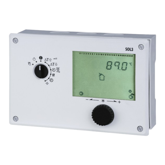
SOL3-1 1 Operation The controller is factory-provided with standard temperature settings and timing programs and therefore ready for use. The current date and time have to be set at initial operation of the controller (Chapter 1.5). 1.1 Controls The operational controls are located on the front side of the controller. -
Page 6: Rotary Switch
(Controller remains in operation) Manual operating mode: manual pump control Rotary switch – Settings Solar-Turn-on threshold Solar-Turn-off threshold Usage schedules for heating and hot water Party mode System time: Setting time, date and year Configuration and settings level not available for SOL3-1 EB_37381_SOL3-1_EN002... -
Page 7: Operating Modes
SOL3-1 1.2 Operating modes Normal operating mode off Normal operating mode is always off, only pump blocking protection and equipment anti- freeze is ensured (if activated). Manual operating mode Manual pump operation (chapter 3). 1.3 Display During operation, the display shows the current time as well as informations about the status of the controller. -
Page 8: Retrieving Data - Information Level
Installation and operating manual KT-Elektronik The following applies to the icon of the collector pump: Description Symbol Icon off Pump off Condition to turn on the pump is met but the Icon flashes briefly pump is still off because of the minimum idle time. -
Page 9: Setting The System Time
SOL3-1 1.5 Setting the system time System time and date have to be set during first start-up and after each loss of power with a duration of more than 24 hours. This is indicated by a blinking time display. Procedure: Turn rotary switch to the position “system time”... -
Page 10: Access Advanced Information Level
Installation and operating manual KT-Elektronik 1.6 Access advanced information level After entering the access code 1999 the following informations are accessible through the menu items as described in chapter 1.4: •Binary input switching status •Info 2 - The following values are sequentially displayed: Controller-ID Memory usage, Data logging module (chapter 7.9) -
Page 11: Prescribe Temperature Set-Points
SOL3-1 1.7 Prescribe temperature set-points The solar circuit of the controller can be programmed with turn-on and turn-off thresholds. The turn-on threshold determines how much the temperature of the collector (at least) has to be higher than the storage temperature in order to allow to turn on the pump. -
Page 12: Operation Level Stucture
Installation and operating manual KT-Elektronik 1.8 Operation level stucture Information level Figure 1: Level structure PA3/CO3: Solar circuit PA5/CO5: general PA6/CO6: Communication Anl: system variant ID 2 Commissioning The configuration procedures and parametrization described in this chapter can only be performed by entering a valid controller access code. -
Page 13: Activate And Deactivate Functions
SOL3-1 2.1 Activate and deactivate functions Each function can be activated within its related function block. The sequence of numbers shown at the head of the display (0 to 24) represent the function block numbers. When accessing the configuration level, a black square is displayed right hand below active function block numbers. -
Page 14: Edit Settings
Installation and operating manual KT-Elektronik To configure more function blocks, repeat the steps highlighted in grey. Select End Leave configuration level. Select End Return to Information level 2.2 Edit settings Depending on the current system variant ID and active functions, not all parameters listed in the parameter list in the Appendix will be accessible (–>... -
Page 15: Sensor Calibration
SOL3-1 2.3 Sensor calibration The controller is designed for connection of Pt1000-sensors. The sensor values of resistance are listed on page 46. If the temperature values displayed by the controller do not match the real temperatures, the measured values of the connected sensors can be adjusted. The temperature value displayed has to be replaced by the value measured directly at the measuring point (reference value). -
Page 16: Reset To Factory Default Settings
Installation and operating manual KT-Elektronik 2.4 Reset to Factory default settings All parameters set by means of the rotary switch as well as the parameters set in level PA3 and PA5 can be reset to factory default settings, Procedure: Switch to configuration and settings level. -
Page 17: Manual Operating Mode
SOL3-1 3 Manual operating mode The manual operating mode allows the configuration of all outputs (Chapter 9). Manual operating mode is set with the turn switch for the requested circuit: Procedure: Move rotary switch to position “Manual operating mode”. Select menu item in compliance with the control circuit:... -
Page 18: Solar Circuit Functions
4 Solar circuit functions 4.1 System diagram Figure 2: System diagram The solar controller SOL3-1 is used to control solar thermal systems with one collector array and one storage tank. 4.1.1 Basic control functions The controller monitors the collector temperature (sensor CF) as well as the storage temperature (sensor SF) and turns the collector pump (CP) on once enough solar energy is available to heat up the storage tank. - Page 19 SOL3-1 Figure 3: temperature chart A) The collector temperature exceeds the storage temperature by more than the turn-on threshold (8 K). The collector pump is turned on. B) The collector temperature dropped below the turn-off threshold (SF + 4 K). The collector pump is turned off.
-
Page 20: Limiting The Storage Temperature
Installation and operating manual KT-Elektronik Parameters for the basic function: Setting Parameter level / Value range Turn-on threshold Direct input Turn-off threshold Direct input Pump minimum run time 60 s PA3 / 0 to 1800 s Pump minimum idle time... -
Page 21: Collector Minimum Temperature
SOL3-1 4.1.4 Collector minimum temperature A minimum collector temperature can be set, underneath which the pump is not turned on at all. This can be reasonable in cases where it is known that the solar gain ratio lays below the pump power ratio. -
Page 22: Forced Pump Operation (Anti-Locked)
Installation and operating manual KT-Elektronik 4.1.6 Forced pump operation (anti-locked) If the pump has not been turned on for 24 hours, it is turned on by force between 12:02 and 12:03 to prevent that it gets stuck in long term idle periods. -
Page 23: System Wide Functions
SOL3-1 5 System wide functions 5.1 Automatic summer/winter switching Switching is done automatically on the last Sunday in March at 2.00 am and on the last Sunday in October at 3.00 am. Functions Configuration Summer/winter switching CO5 -> F08 - 1 5.2 Locking manual operating mode... -
Page 24: Enter A Valid Individual Access Code
Installation and operating manual KT-Elektronik 5.4 Enter a valid individual access code The standard access code can be replaced by an individual code to prevent unauthorized function or parameter changes. The individual code can be selected from 0100 to 1900. -
Page 25: Malfunction
SOL3-1 6 Malfunction A system malfunction is indicated by a flashing icon in the display. An error message is immediately displayed. The error level is opened by pressing the control button. A larger number of error messages might eventually be retrieved by turning the control button. -
Page 26: Temperature Monitoring
Installation and operating manual KT-Elektronik 6.3 Temperature monitoring If the collector temperature deviates more than 50 K from the turn-on threshold with running collector pump for a period of 30 minutes, the error message "Err 6" is generated (temperature monitoring alarm). -
Page 27: Sms Delivery In Case Of A System Failure
SOL3-1 6.5 SMS delivery in case of a system failure If a dial up modem is connected to the KOM232M communication module (chapter 7.1), the controller is able to send error messages to a cell phone. An SMS is sent as soon as a failure is captured in the error status register. -
Page 28: Communication
Installation and operating manual KT-Elektronik 7 Communication The solar controller SOL3 can be connected to a building control system via an optional communication module. A suitable software allows to set up a complete control system for process visualization and communication. -
Page 29: Communication Module Kom232Pc
SOL3-1 7.1 Communication module KOM232PC The connector for the optional communication module (Mat-No. 11988) is located on the left side (front panel view) inside the controller housing (RJ45 connector). The operation of the controller in conjunction with the communication module KOM232PC requires the use of appropriate communication tools (software). - Page 30 Installation and operating manual KT-Elektronik As long as valid Modbus queries are captured, the controller resets the time monitoring; but after a lapse of 30 minutes all collective level bits are reinitialized to "autonomous". ATTENTION! When installing, the relevant standards and regulations related to lightning protection and over-voltage/voltage surge protection have to be attended to.
-
Page 31: Communication Module Kom232M
SOL3-1 7.3 Communication module KOM232M The connector for the optional communication module (Mat-No. 11988) is located on the left side (front panel view) inside the controller housing (RJ45 connector). The communication module KOM232M allows the connection of a dial up modem to the controller. -
Page 32: Data Modem Datamod11
Installation and operating manual KT-Elektronik Wiring diagram for communication module KOM232M 7.4 Data Modem DataMod11 The connector for the optional data modem DataMod11 (Mat-No. 11991) is located on the left side (front panel view) inside the controller housing (RJ45 connector). Settings and notes from chapter 7.3 remain valid. -
Page 33: Modbus-Mbus-Gateway
SOL3-1 7.5 ModBus-MBus-Gateway The connector for the optional ModBus-MBus-Gateway (Mat-No. 11997) is located on the left side (front panel view) inside the controller housing (RJ45 connector). The operation of the controller in conjunction with the ModBus-MBus-Gateway requires a permanent bus connection (data cable). -
Page 34: Memory Module
Installation and operating manual KT-Elektronik A dialling pause (approx 3 to 5 minutes) should be kept within two BCS/SMS provider calls in order not to permanently stress the telecommunication network. The modem dialling pause is programmed as period between two dial attempts. -
Page 35: 55Viewer For Visualization And Remote Maintenance
SOL3-1 7.8 55Viewer for visualization and remote maintenance. The software 55Viewer (Mat-No. 37160) is available to visualize and remote maintain the system. The software allows to display a graphical representation of the complete system installation with all sensor data and all switching states of the pump and valve outlets. -
Page 36: Data Logging
Installation and operating manual KT-Elektronik 7.9 Data Logging The data logging module (part no. 1400-9378) allows saving the following controller data in two minute intervals: Sensor readings Switching states of the pump outlets Error status register and archive ... -
Page 37: Mounting
SOL3-1 8 Mounting The device consists of a controller housing containing the electronics assembly and a mounting panel with the terminal strips. It is suited for control panel, wall and DIN rail mounting (Figure 5). Control panel mounting Loose both screws (1). - Page 38 Installation and operating manual KT-Elektronik Figure 5: Mounting EB_37381_SOL3-1_EN002...
-
Page 39: Electrical Connection
SOL3-1 9 Electrical connection ATTENTION! VDE and utility specifications and regulations have to be attended to when wiring and connecting the controller. Therefore, this task has to be performed by qualified personnel only! Notes for wire installation ● 230 V-supply lines and signal lines must be routed in separate cables! To... -
Page 40: Wiring Diagram
Installation and operating manual KT-Elektronik Connecting the pumps All wires with a minimum diameter of 1.5 mm² are to be connected to the controller according the wiring diagram. Legend for the connection diagrams: Collector sensor Storage sensor Collector pump 9.1 Wiring diagram... -
Page 41: Appendix
SOL3-1 10 Appendix 10.1 Function block lists CO3: Solar circuit Function Function block parameter description/value range (factory default setting) Forced pump CO3 F01 = 1 - Regular Forced pump operation active operation chapter 4.1.6 Collector antifreeze CO3 F02 = 1 - Antifreeze active chapter 4.1.7... -
Page 42: Parameter Lists
Installation and operating manual KT-Elektronik CO6: Modbus Function Sys. Function block parameter description/value range (factory default setting) Modbus CO6 -> F01 - 1: Modbus active Modbus-16-bit only with CO6 -> F01 – 1 addressing CO6 -> F02 - 1: 16-bit addressing, CO6 ->... - Page 43 SOL3-1 Symbol/Icon Parameter name Value range (factory default) Maximum allowed storage tank temperature (turn-off value) °C ST O P 50 to 160 °C (60 °C) Maximum allowed storage tank temperature (turn-on value) °C START 50 to 160 °C (58 °C)
- Page 44 Installation and operating manual KT-Elektronik Symbol/Icon Parameter name Value range (factory default) Minimum allowed collector temperature (turn-on value) °C STA RT –20 to 50°C (35°C) PA6: Modbus parameter Symbol/Icon Parameter name Value range Modbus client address 1 to 247 (255) (with CO6 ->...
- Page 45 SOL3-1 Symbol/Icon Parameter name Value range Number of BCS dial attempts (C) 0 to 255 (15) Phone number of the BCS (TELnr) max. 22 digits; 1, 2, 3, …, 9, 0; „-“ = End of string „P“ = Pause SMS service numbers (TAPnr) max.
-
Page 46: Resistance Values
Installation and operating manual KT-Elektronik 10.3 Resistance values Resistance values with Pt 1000-measuring element Typ2 5277-2 (immersion sleeve required) and 5267-2 (contact sensor). Temperature Resistance value with Pt1000 sensor 842.7 Ω ° ° 882.0 Ω 921.6 Ω ° 960.9 Ω... -
Page 47: Technical Specifications
SOL3-1 10.4 Technical specifications Inputs 2 Inputs for temperature sensor Pt 1000 or BE Outputs 1 x Pump output: Max. power handling 250 V AC, 2A; Relay output with varistor (snubber) Optional interfaces 1 x Modbus interface RS-232 for modem connection... -
Page 48: Accessories
Installation and operating manual KT-Elektronik 10.5 Accessories Part no. Name Description 11988 KOM232PC Adapter to connect the SOL3 to the RS232 plug (PC) Adapter to connect the modem to the SOL3 (analogue / 11989 KOM232M GSM / ISDN) 11994 iCon485... - Page 49 SOL3-1 Function block settings in configuration levels EB_37381_SOL3-1_EN002...
- Page 50 Installation and operating manual KT-Elektronik Parameter PA3 (solar circuit) Setting Value range Pump minimum run time 0 to 1800 s Pump minimum idle time 0 to 1800 s 50 to 160 °C Maximum storage tank temp. (turn-off condition) 50 to 160 °C Maximum storage tank temp.
-
Page 51: Important Abbreviations
SOL3-1 10.7 Important abbreviations Collector sensor Storage sensor Collector pump Binary output Binary input Configuration level Installation and operating manual Function block GLT, BCS Building control system Kl, T. Terminal Parameter level Control circuit time Temperature Default factory setting Common ground 10.8 Access codes... - Page 52 KT-Elektronik GmbH Berlinickestrasse 11 12165 Berlin- Germany Telephone: +49 30 790805-0 Telefax: +49 30 790805-20 E-mail: info@kt-elektronik.de EB_37381_SOL3-1_EN002 Internet: www.kt-elektronik.de...
Need help?
Do you have a question about the SOL3-1 and is the answer not in the manual?
Questions and answers