Table of Contents
Advertisement
Quick Links
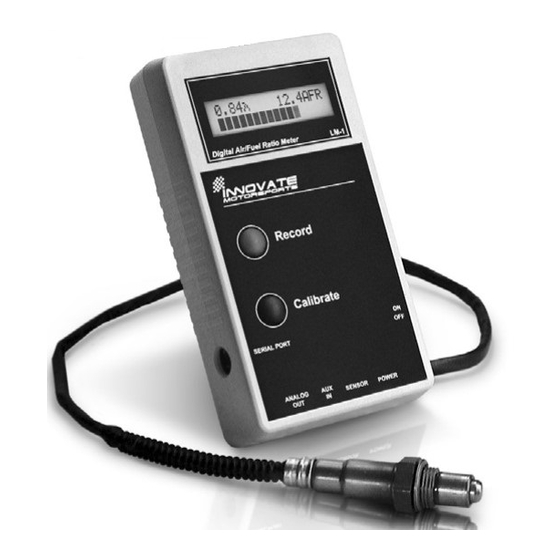
LM-1 Digital Air/Fuel Ratio (Lambda) Meter
Manual
9/03/03
Warning!
The Oxygen Sensor used in this device gets very hot in operation.
Do not touch the hot sensor. Do not let a hot sensor touch a combustible surface.
Do not use the sensor with or near flammable liquids or gases. Failure to heed
these warnings may result in severe burns, explosions or fires.
When installed in the exhaust, the oxygen sensor MUST be connected and
operating with the LM-1 whenever the car is running. An un-powered oxygen
sensor will be quickly damaged when exposed to hot exhaust gases.
Advertisement
Table of Contents

Related Manuals for MD Mustang Dynamometer

Summary of Contents for MD Mustang Dynamometer
- Page 1 LM-1 Digital Air/Fuel Ratio (Lambda) Meter Manual 9/03/03 Warning! The Oxygen Sensor used in this device gets very hot in operation. Do not touch the hot sensor. Do not let a hot sensor touch a combustible surface. Do not use the sensor with or near flammable liquids or gases. Failure to heed these warnings may result in severe burns, explosions or fires.
-
Page 2: Table Of Contents
Table of Contents Table of Contents ..........................2 1. Overview............................3 2. The LM-1 Instrument ........................3 2.1. The LM-1 Instrument (included).................... 3 3. First Time Use ..........................5 4. Installation............................ 6 4.1 Mounting the sensor ......................6 5. Operation ............................. 7 6. -
Page 3: Overview
1. Overview The LM-1 is a hand-held instrument used to measure the Air/Fuel Ratio (AFR) or Lambda for an engine. For gasoline-driven engines, the theoretically optimal air fuel ratio is 14.7 pounds of air for every pound of fuel. At this ratio theoretically all available oxygen in the air combines with all available fuel. - Page 4 2.2 Included cables and devices Oxygen Sensor Sensor Cable Power cable Serial Cable Also included: 9V Battery Bung/Plug set - 4 -...
-
Page 5: First Time Use
3. First Time Use 1. Install the included 9V battery in the battery compartment on the bottom of the instrument. 2. Connect the power cable to the 12V Power connector and plug the other end in your cigarette lighter socket in your car. Note that the 9V battery is for powering the LM-1 electronics and display, but it cannot power the oxygen sensor. -
Page 6: Installation
4. Installation 4.1 Mounting the sensor On non-catalytic converter vehicle: After the instrument is calibrated, and the vehicle's engine is warmed up, readings can be taken from the engine’s exhaust. A probe clamp is required if the vehicle will be in motion (not just on the dyno), and is recommended even when the vehicle is stationary. -
Page 7: Operation
5. Operation Once the LM-1 has been installed and is in place (see Chapter 4: Installation), lambda measurements can be taken. In operation the meter's display shows: Showing the current lambda value and air-fuel-ratio. The numeric lambda and air-fuel-ratio values are averaged over about 0.2-0.3 seconds so that the numbers are more consistent and easy to read. -
Page 8: Recording Other Vehicle Data With The Lm-1
7. Recording other vehicle data with the LM-1 7.1 Overview The LM-1 has the capability to record other vehicle data from other vehicle sensors while driving so as to compile a complete log of engine data. The AUX input connector of the LM-1 allows connecting up to 5 other sensors to the LM-1 whose data values will be recorded. -
Page 9: Special Considerations When Installing Lm-1 Permanently In The Vehicle
allows these instruments to be used as true remote AFR or lambda meters. Connecting these meters to the second analog output of the LM-1 allows to use them as true remote AFR meters, provided the LM-1 analog output is programmed to the characteristics of the used meter. The LM-1's second analog output is factory programmed to provide a linear output between 1V and 2V for an AFR of 10 to 20, allowing using a digital voltmeter as AFR display. -
Page 10: Programming The Lm-1
9. Programming the LM-1 The LM-1 is programmable with the following functionality: 1. Change the relationship between Lambda and AFR. 2. Upgrade and change the software. 3. Switch between sensor types. 4. Change the output characteristics of the Analog outputs. 5. -
Page 11: Resetting The Calibration Data
9.4 Updating the software Click the 'Update Software' in the main page. Update software for the LM-1 has the extension dld. You can download the latest LM-1 software from the Mustang Dynamometer web-site at www.mustangdyne.com If your computer crashes during a download, the LM-1 has a recovery mechanism where it will be able to retry the download again and not be disabled by half loaded software. -
Page 12: Changing The Sensor Type
9.5 Changing the sensor type The LM-1 device is compatible with the following sensors: Device Name OEM Part Number Bosch LSU 4.2 0 258 007 057/058 Bosch LSU 4 0 258 006 066 NTK L1H1 L1H1 To switch a LM-1 to a different sensor type, follow these steps: 1. -
Page 13: Programming The Analog Outputs
9.6 Programming the analog outputs Select one of the Analog output tabs. The Analog output page looks like this: This shows the analog output voltages versus Lambda for one of the two analog outputs. The graph display is automatically scaled to the selected voltages. For each output you can specify a minimum and maximum lambda value and the associated voltages. -
Page 14: Downloading Recorded Data
9.7 Downloading recorded data Select the 'Data Logger' tab. The download page appears: This display is organized in 6 columns. The two rightmost columns are used only if you hooked up the optional LM-1 Aux expander module. See details how to use them in the LM-1 Aux expander manual. The column from left to right: 1. - Page 15 The scale will be automatically expanded to a 0-5V scale. Clicking the check mark in this column switches the input back to either voltage or sample data mode. 4. Input in Use Check the button if this input is actually hooked up. The LM-1 will record from each input regardless if the input is actually connected to something or not.
- Page 16 9.7.5 Graphing the log data. Click the ‘Show’ button. The log data will be shown as graph as in the following display: Select the vertical scale for the input of interest by clicking on the appropriate input selection button in the lower left hand corner of the graph window. You can hide or show a trace by right- clicking on the appropriate input selection button.
- Page 17 9.7.6 Printing the log data graph. To print a graph press the button. The printer dialog appears: This dialog is divided into four sections: In the ‘Printer’ section select the printer to use. Usually you do not need to touch this section. The ‘Print range’...
-
Page 18: Tips, Tricks And Troubleshooting
10. Tips, Tricks and Troubleshooting 10.1 General measurement requirements The LM-1 measures the air-fuel-ratio by measuring the amount of oxygen in the exhaust for lean conditions or the amount of unburned or partially burned fuel for rich conditions. An exhaust leak will allow oxygen to enter the exhaust stream and therefore will measure leaner than the engine is actually running. -
Page 19: Sensor Timing Errors
Under some rare circumstances it is possible that the heater calibration data in the LM-1 is partially destroyed. This can manifest in the above-mentioned errors. Follow the steps in chapter 3 ‘First time use’ to reset the heater calibration data. 10.6 Sensor Timing Errors These errors are typically encountered when the sensor does not have outside air available as reference gas. -
Page 20: Advanced Topics
11 Advanced Topics 11.1 Connecting the LM-1 to simulate a narrow band oxygen sensor. It is possible to install the wide-band sensor in place of the OEM oxygen sensor. In this case the meter's analog output signal will replace the OEM oxygen sensor's signal to the fuel injection computer. -
Page 21: Using A Serial Remote Lcd Display
Typically the 4 wires are heater power, heater ground, sensor ground, and sensor element connection. Proceed as for the 3-wire sensor. 11.2 Using a Serial Remote LCD Display The optional serial remote LCD display ( LMD) connects to the serial port of the LM-1. It has the identical display functions as the built-in LCD display and also provides a 'Record' button.To use the LMD click on the serial display button on the main screen of the LM-1 Manager. -
Page 22: Appendix A: Lm-1 Accessories
Appendix A: LM-1 Accessories A.1 Analog output cable This cable comes with stripped ends to allow you to connect it up easily. Output 1 is the red wire, Output 2 is the white wire, Ground is the bare copper shield. A.2 Auxiliary Input Cable This cable has 6 screw connectors at one end and a Mini-DIN 7 plug at the other end. - Page 23 A.5 Remote serial display LMD This unit is intended to be dash-mounted so that the LM-1 instrument can be mounted out of sight. Its power is supplied by the LM-1 and it connects to the LM-1 serial port. A.6 LM1 Aux Expander, (“AuxBox”) The LM1 Aux Expander contains four sensors and converters: 1.
- Page 24 A.7 LM-1 Exhaust Clamp A.8. LM1-Wall Transformer (Wall-Wart) Note: see Quick start guide or website for current accessory pricing and availability - 24 -...
-
Page 25: Appendix B: Lm-1 Cable Pinouts
Appendix B: LM-1 Cable Pinouts B1. Serial Interface (Mini-DIN8 female connector) Serial Interface: 19.2 kBaud 8 Data bits 1 Stop bit no parity no hardware handshaking Pin Assignments Lambda Meter Mini-DIN8 Signal Computer DB-9 Computer DB-25 Connected to +5V B2. Aux Input Connector (Mini-DIN7 female connector) Note: Connect to signal of maximum 5V only. - Page 26 Lambda Meter Mini-DIN7 Signal Ground Sensor 5 Input Sensor 1 Input Sensor 4 Input Sensor 2 Input Sensor 3 Input +5V from Meter B3. Analog Outputs (3.5mm Stereo connector) Stereo plug shown Pin Assignments Lambda Meter Stereo Signal Analog output 1 Analog output 2 Ground - 26 -...
- Page 27 B4. Sensor Interface Connector (Standard DIN-5 female) Pin Assignments Lambda Meter Signal Pump+ Sens+ Heater - Pump-/Sens- Heater + B5. Power Connector (3.5mm power connector female) - 27 -...
-
Page 28: Appendix C: Lm-1 Error Codes
Appendix C: LM-1 error codes Error 1 Heater circuit shorted Error 2 Heater circuit open Error 3 Pump cell circuit shorted Error 4 Pump cell circuit open Error 5 Reference cell circuit shorted Error 6 Reference cell circuit open Error 7 General System error (typically a software error). -
Page 29: Appendix D: Limited Warranty
Appendix D: Limited Warranty LIMITED WARRANTY Mustang stands behind the quality of its products. Mustang makes the following warranty to purchasers of its products: All new Mustang products carry a six-month warranty from the date of purchase. If proof of purchase cannot be provided, warranty will be determined by date of manufacture. -
Page 30: Revision History
Revision History 1.0 – 5/12/03 Initial release 1.1- 5/14/03 Corrected misc. errata. 2.0 – 6/15/03 Complete revision and update, incl. sections 6, 9, 10, 11 2.1 – 6/20/03 Corrected misc. errata. 2.2 – 6/21/03 Reformatting of TOC. 2.3 – 6/25/03 Corrected/updated Appendix B 2.4 –... - Page 31 Filename: LM-1_Manual_2.8.doc Directory: C:¥Documents and Settings¥Administrator.INNOVATE.000¥Desktop Template: C:¥Documents and Settings¥Administrator.INNOVATE.000¥Application Data¥Microsoft¥Templates¥Normal.dot Mustang Dynamometer Title: Subject: Author: Temp1 Keywords: Comments: Creation Date: 9/3/2003 2:22 PM Change Number: Last Saved On: 9/3/2003 2:25 PM Last Saved By: Administrator Total Editing Time: 1 Minute Last Printed On: 9/3/2003 2:25 PM As of Last Complete Printing...
Need help?
Do you have a question about the Mustang Dynamometer and is the answer not in the manual?
Questions and answers