Table of Contents
Advertisement
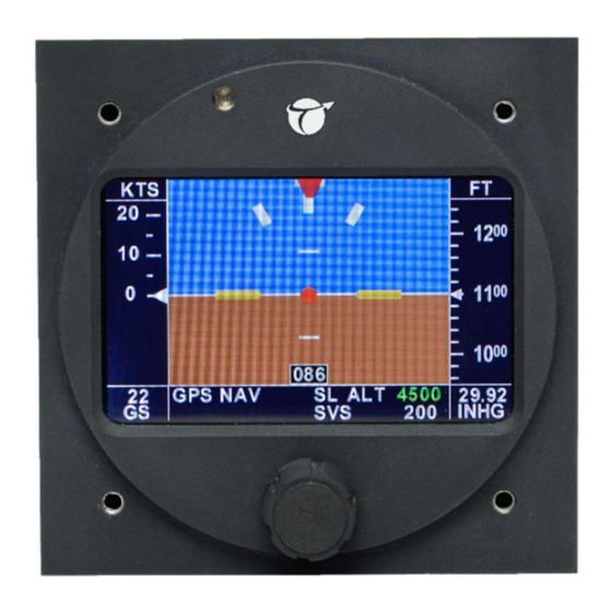
XCRUZE 110 INSTALLATION MANUAL
P/N 8300-088 Rev 1
Jan 2020
Honeywell International, Inc.
9201-B San Mateo Blvd N.E.
Albuquerque, New Mexico 87113 U.S.A.
Telephone: 855-250-7027 (Toll Free U.S.A./Canada)
Telephone: 602-365-7027 (International Direct)
Export Control
This document contains technical data and is subject to U.S. export regulations. These commodities,
technology, or software were exported from the United States in accordance with the export
administration regulations. Diversion contrary to U.S. law is prohibited.
ECCN: 7E994
© Honeywell International Inc. Do not copy without express permission of Honeywell.
Advertisement
Table of Contents

Related Manuals for BENDIXKing XCRUZE 110


Summary of Contents for BENDIXKing XCRUZE 110
- Page 1 XCRUZE 110 INSTALLATION MANUAL P/N 8300-088 Rev 1 Jan 2020 Honeywell International, Inc. 9201-B San Mateo Blvd N.E. Albuquerque, New Mexico 87113 U.S.A. Telephone: 855-250-7027 (Toll Free U.S.A./Canada) Telephone: 602-365-7027 (International Direct) Export Control This document contains technical data and is subject to U.S. export regulations. These commodities, technology, or software were exported from the United States in accordance with the export administration regulations.
- Page 2 _____________________________________________________________________________________ Blank Page 8300-088 xCruze 110 Installation Manual Rev 1 Page T-2 © Honeywell International Inc. Do not copy without express permission of Honeywell.
- Page 3 No license to use any Honeywell trademarks or patents is granted under this License Agreement. 8300-088 xCruze 110 Installation Manual Rev 1 Page T-3 © Honeywell International Inc. Do not copy without express permission of Honeywell.
- Page 4 10. Remedies - Honeywell reserves the right to pursue all available remedies and damages resulting from a breach of this License Agreement. 8300-088 xCruze 110 Installation Manual Rev 1 Page T-4 © Honeywell International Inc. Do not copy without express permission of Honeywell.
- Page 5 The user must know the manufacturer/ supplier data and obey the procedures, recommendations, warnings and cautions set forth for the safe use, handling, storage, and disposal of the materials. 8300-088 xCruze 110 Installation Manual Rev 1 Page T-5 © Honeywell International Inc. Do not copy without express permission of Honeywell.
- Page 6 Changes to this manual are provided to users who have registered via the website to receive updates. BendixKing Customer Support If you need to speak to personnel about Technical matters, the BendixKing Customer Support team provides 24/7 customer service. ...
- Page 7 _____________________________________________________________________________________ RECORD OF REVISIONS Revision Revision Date Description 4/30/2015 Initial release 1/31/2020 BendixKing Version 8300-088 xCruze 110 Installation Manual Rev 1 Page T-7 © Honeywell International Inc. Do not copy without express permission of Honeywell.
-
Page 8: Table Of Contents
_____________________________________________________________________________________ TABLE OF CONTENTS INTRODUCTION ...........................1 How to Use This Manual ......................1 1.1.1 General..........................1 1.1.2 Observance of Manual Instructions ..................1 1.1.3 Symbols ..........................1 1.1.4 Units of Measure ......................... 2 1.1.5 Electrostatic Discharge ......................2 References ..........................2 1.2.1 Other Publications ....................... - Page 9 _____________________________________________________________________________________ LIST OF FIGURES Figure 1-1 Symbols ............................1 Figure 6-1 Rear 25-Pin Connector P101 Viewed from rear of unit .............. 9 LIST OF TABLES Table 1-1 Publications ..........................2 Table 1-2 Acronyms and Abbreviations ....................... 3 Table 6-1 P101 Pin Connections ........................9 Table 9-1 Garmin 155XL/250XL/300XL Connections .................
-
Page 10: Introduction
_____________________________________________________________________________________ 1 INTRODUCTION How to Use This Manual 1.1.1 General (1) This publication gives installation and maintenance instructions for the equipment shown on the Title page. (2) Standard maintenance procedures that technicians must know are not given in this manual. (3) Warnings, cautions, and notes in this manual give the data that follows: A WARNING gives a condition or tells personnel what part of an operation or maintenance procedure, which if not obeyed, can cause injury or death. -
Page 11: Units Of Measure
_____________________________________________________________________________________ 1.1.4 Units of Measure Measurements, weights, temperatures, dimensions, and other values are expressed in the USMS followed by the appropriate SI metric units in parentheses. Some standard tools or parts such as drills, taps, bolts, nuts, etc. do not have an equivalent. 1.1.5 Electrostatic Discharge Touch the items susceptible to electrostatic discharge in accordance with MIL-HDBK-263. -
Page 12: Acronyms And Abbreviations
_____________________________________________________________________________________ Acronyms and Abbreviations (1) The abbreviations are used in agreement with ASME Y14.38. (2) Acronyms and non-standard abbreviations used in this publication are as follows in Table 1-2. Table 1-2 Acronyms and Abbreviations Acronyms and Definition Abbreviations Advisory Circular AHRS Attitude and Heading Reference System Ampere... - Page 13 _____________________________________________________________________________________ Acronyms and Definition Abbreviations kbps kilobytes per second Kilogram kilopascal Pound Meter millibars minute Millimeter Miles per hour Not Applicable NiMh Nickel-Metal Hydride Number Newton Meter Non-Volatile Memory Printed Board Assembly PBIT Power-up Built-in Test Personal Computer Part Number Pub.
-
Page 14: General Information
_____________________________________________________________________________________ 2 GENERAL INFORMATION Introduction This manual gives installation instructions for the xCruze 110 Autopilot PN 8000-150 (formerly known as TruTrak Gemini). 8300-088 AeroCruze 110 Installation Manual Rev 1 Page 5 © Honeywell International Inc. Do not copy without express permission of Honeywell. -
Page 15: Mechanical Considerations
_____________________________________________________________________________________ 3 MECHANICAL CONSIDERATIONS The installation information in this section is extremely important and must be clearly understood by the installer. Improper servo installation or failure to observe and diagnose installation problems prior to flight can result in extremely serious consequences, including loss of ability to control the aircraft. -
Page 16: Controller Installation
4 CONTROLLER INSTALLATION Mounting Considerations The xCruze 110 autopilot controller unit is designed to mount in the aircraft instrument panel within view and reach of the pilot. Maximum recommended viewing angle should be no more than 20 deg. The maximum mounting angle the xCruze 110 can accommodate is 10 degrees longitudinal (pitch) axis and 0 degrees lateral (roll or yaw) axis. -
Page 17: Rfi/Emi Considerations
-6) Toggle the joystick down to select a 500 fpm descent. Make sure the controls move forward. If steps 2-6 are all verified then the xCruze 110 AP is ready to be engaged in flight. *For instructions on accessing the setup menus and adjusting autopilot settings, please see the Autopilot Operating Manual. -
Page 18: Electrical Pin Information
_____________________________________________________________________________________ 6 ELECTRICAL PIN INFORMATION The table below provides a brief explanation of each pin function on the main 25-pin connector P101. 9 10 11 12 13 14 15 16 17 18 19 20 21 22 23 24 25 Figure 6-1 Rear 25-Pin Connector P101 Viewed from rear of unit Table 6-1 P101 Pin Connections P101 Function... - Page 19 _____________________________________________________________________________________ P101 Function Notes J101 Pin 20 Pin 21 Standard J201-4 J201-5 Servo CCW (counter- clockwise) RIGHT Reversed J201-5 J201-4 Servo CW (clockwise) RIGHT TCB-A Unused at this time, for future expansion. TCB-B 8300-088 AeroCruze 110 Installation Manual Rev 1 Page 10 ©...
-
Page 20: Autopilot Wiring Diagram
_____________________________________________________________________________________ 7 AUTOPILOT WIRING DIAGRAM 8300-088 AeroCruze 110 Installation Manual Rev 1 Page 11 © Honeywell International Inc. Do not copy without express permission of Honeywell. -
Page 21: Controller Cut-Outs And Dimensions
_____________________________________________________________________________________ 8 CONTROLLER CUT-OUTS AND DIMENSIONS 8300-088 AeroCruze 110 Installation Manual Rev 1 Page 12 © Honeywell International Inc. Do not copy without express permission of Honeywell. -
Page 22: Gps Setup Guide
_____________________________________________________________________________________ 9 GPS SETUP GUIDE Many new handheld GPS’s have adequate output required to fly a TruTrak autopilot. Although most support data output not all handhelds will provide consistent and reliable information required to fly all TruTrak autopilots. Therefore, some handhelds will not fly the airplane well. Performance may decline by putting the processor in high-load situations. -
Page 23: Garmin Gps 196/295
_____________________________________________________________________________________ Press the MENU key twice. Select ‘Set-Up Menu’. Press ENTER. Select ‘Input/Output’. Press ENTER. The input/output format is ‘No In/NMEA Out.’ Note that the baud rate is automatically set at 4800 bps. Note: This is the baud rate that will need to be entered in the setup mode of the autopilot. Now the Garmin 195 is correctly set up to provide the RS-232 serial output required by your TruTrak autopilot. -
Page 24: Garmin Gps 396/496
_____________________________________________________________________________________ Now the Garmin 296 is correctly set up to provide the RS-232 serial output required by your TruTrak autopilot. Garmin GPS 396/496 The Garmin 496 must be configured to provide the correct output to the autopilot. Press the MENU key twice. Use the rocker keypad to select the SETUP in the vertical tabs. Use the rocker keypad to select the ‘Interface’... -
Page 25: Avmap Ekp Iv
Garmin 430 and 530 connections to autopilot P4001 [P5001] on Signal Name Signal Name P101 on Garmin 430 [530] (Garmin) (TruTrak) xCruze 110 AP GPS RS 232 OUT 1 Primary Serial Input GPS ARINC 429 OUT A ARINC-A GPS ARINC 429 OUT B ARINC-B 8300-088... -
Page 26: Upsat Gx-50/60/65
P101 on on UPSAT (UPSAT) (TruTrak) xCruze 110 AP GX-50/60/65 Use pin 5 – TxD1 – if GX has no GPSS Primary Serial Input Power the GX-50/60/65 up and turn it on while holding down the leftmost and rightmost “smart keys.”... -
Page 27: Garmin At Gns480
Table 9-4 Garmin 430 and 530 Connections Garmin AT GNS480 connections to autopilot P1 on GNS480 Signal Name (Garmin AT) Signal Name (TruTrak) P101 on xCruze 110 AP RS232 TxD2 Primary Serial Input P5 on GNS480 Signal Name (Garmin AT) Signal Name (TruTrak) -
Page 28: Garmin 695/696/795/796
Signal Name P101 on Cable (Garmin) (TruTrak) xCruze 110 AP Blue Wire GPS RS 232 OUT 1 Primary Serial Input Select Tools -> Setup -> Interface Select the drop down menu under Serial Data Format. Choose one of the formats that outputs NMEA Out. -
Page 29: Garmin Aera 500-510-550-560
Garmin G3X connections to TruTrak autopilot P3701 (GDU 37X) Signal Name Signal Name P101 on (Garmin) (TruTrak) xCruze 110 AP GPS RS 232 OUT 1 Primary Serial Input GPS RS 232 IN 1 Serial Output P731 (GSU 73) if P101 on... - Page 30 © Honeywell International Inc. Do not copy without express permission of Honeywell.
Need help?
Do you have a question about the XCRUZE 110 and is the answer not in the manual?
Questions and answers