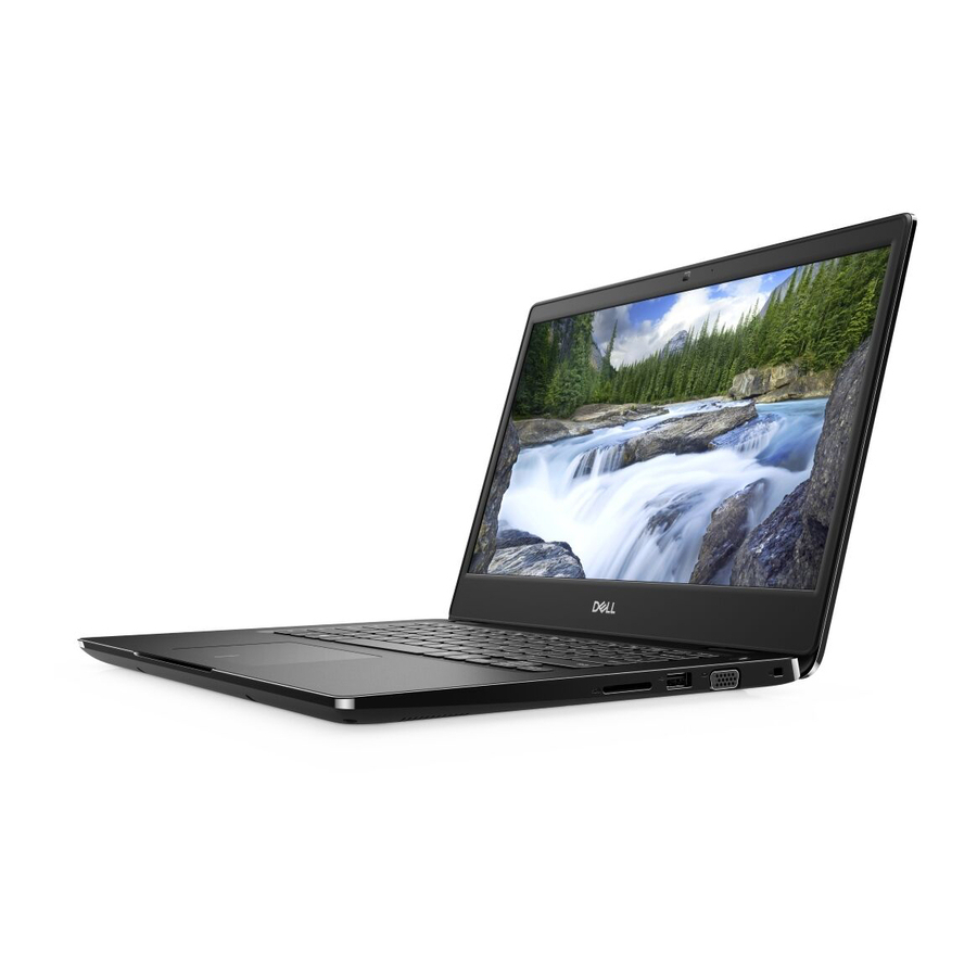
Dell Latitude 3400 Service Manual
Hide thumbs
Also See for Latitude 3400:
- User manual ,
- Service manual (139 pages) ,
- Setup and specifications manual (39 pages)

Related Manuals for Dell Latitude 3400


Summary of Contents for Dell Latitude 3400
- Page 1 Dell Latitude 3400 Service Manual Regulatory Model: P111G Regulatory Type: P111G001...
- Page 2 VÝSTRAHA označuje potenciálne riziko vecných škôd, zranení osôb alebo smrti. © 2019 firma Dell Inc. alebo jej pobočky. Všetky práva vyhradené. Dell, EMC, ako aj ďalšie ochranné známky sú ochranné známky firmy Dell Inc. alebo jej pobočiek. Ďalšie ochranné známky môžu byť ochranné známky príslušných vlastníkov.
-
Page 3: Table Of Contents
Contents 1 Práca na počítači.......................... 5 Bezpečnostné pokyny................................5 Vypnutie počítača – Windows 10............................5 Pred servisným úkonom v počítači............................6 Po dokončení práce v počítači............................. 6 2 Technológia a komponenty......................7 DDR4....................................... 7 Vlastnosti rozhrania USB..............................8 USB typu C................................... 10 Intel Optane memory................................ - Page 4 5 Troubleshooting........................103 Diagnostika Vylepšené vyhodnotenie systému pred zavedením (Enhanced Pre-Boot System Assessment – ePSA)....................................103 Spustenie diagnostiky ePSA............................103 Diagnostika..................................104 M-BIST..................................104 L-BIST....................................104 Diagnostic LED................................... 104 Kontrolka LED stavu batérie.............................105 6 Získanie pomoci........................107 Kontaktovanie spoločnosti Dell............................107 Contents...
-
Page 5: Práca Na Počítači
Poškodenie v dôsledku servisu, ktorý nie je oprávnený spoločnosťou Dell, nespadá pod ustanovenia záruky. Prečítajte si bezpečnostné pokyny, ktoré ste dostali spolu so svojím produktom, a dodržiavajte ich. -
Page 6: Pred Servisným Úkonom V Počítači
POZNÁMKA Skontrolujte vypnutie počítača a všetkých pripojených zariadení. Ak sa počítač a pripojené zariadenia nevypli pri vypínaní operačného systému automaticky, stlačte a podržte hlavný vypínač po dobu asi 6 sekúnd, čím ich vypnete. Pred servisným úkonom v počítači O tejto úlohe V záujme vyhnutia sa poškodeniu počítača vykonajte predtým, než... -
Page 7: Technológia A Komponenty
Technológia a komponenty DDR4 DDR4 (double data rate fourth generation) memory is a higher-speed successor to the DDR2 and DDR3 technologies and allows up to 512 GB in capacity, compared to the DDR3's maximum of 128 GB per DIMM. DDR4 synchronous dynamic random-access memory is keyed differently from both SDRAM and DDR to prevent the user from installing the wrong type of memory into the system. -
Page 8: Vlastnosti Rozhrania Usb
Figure 3. Curved edge Memory Errors Memory errors on the system display the new ON-FLASH-FLASH or ON-FLASH-ON failure code. If all memory fails, the LCD does not turn on. Troubleshoot for possible memory failure by trying known good memory modules in the memory connectors on the bottom of the system or under the keyboard, as in some portable systems. - Page 9 (s vysokou rýchlosťou) a Full-Speed (s plnou rýchlosťou) a bežne sa zvyknú označovať ako USB 2.0 a 1.1, sú pomalšie a stále ponúkajú prenosovú rýchlosť len 480 Mb/s a 12 Mb/s, no naďalej sa využívajú kvôli spätnej kompatibilite. USB 3.0/USB 3.1 Gen 1 dosahuje oveľa vyšší výkon vďaka nižšie uvedeným technickým zmenám: •...
-
Page 10: Usb Typu C
rovnako umiestnenými kontaktmi USB 2.0. Káble USB 3.0/USB 3.1 Gen 1 obsahujú päť nových spojení na nezávislý prenos prijatých a odosielaných údajov. Do kontaktu prichádzajú len po pripojení k samotnému rozhraniu SuperSpeed USB. USB typu C USB typu C je nový a malý fyzický konektor. Konektor podporuje rôzne zaujímavé nové štandardy rozhrania USB (napríklad USB 3.1) a napájanie cez USB (USB PD). -
Page 11: Povolenie Používania Pamäte Intel Optane
Feature Specifications Capacity 32 GB or 64 GB Povolenie používania pamäte Intel Optane Postup 1. Na paneli úloh kliknite na vyhľadávacie pole a napíšte doň „Intel Rapid Storage Technology“. 2. Kliknite na položku Intel Rapid Storage Technology. 3. Na karte Status (Stav) kliknite na položku Enable (Povoliť), čím povolíte používanie pamäte Intel Optane. 4. -
Page 12: Nvidia Geforce Mx130
Intel UHD Graphics 620 Via Optional USB Type-C Port: VGA, DisplayPort External Connectors HDMI 1.4b USB Type–C port Nvidia GeForce MX130 Tabuľka4. Technické informácie o grafickej karte Nvidia GeForce MX130 Vlastnosť Technické údaje Pamäť grafickej karty 2 GB GDDR5 Typ zbernice PCI Express 3.0 Rozhranie pamäte GDDR5... -
Page 13: Major Components Of Your System
Major components of your system 1. Base cover 2. Power adapter port Major components of your system... - Page 14 15. System fan 16. Heatsink NOTE: Dell provides a list of components and their part numbers for the original system configuration purchased. These parts are available according to warranty coverages purchased by the customer. Contact your Dell sales representative for purchase options.
-
Page 15: Demontáž A Inštalácia Komponentov
Demontáž a inštalácia komponentov Recommended tools The procedures in this document require the following tools: • Phillips #0 screwdriver • Phillips #1 screwdriver • Plastic scribe NOTE: The #0 screw driver is for screws 0-1 and the #1 screw driver is for screws 2-4. Karta SD (Secure Digital) Vybratie karty SD (Secure Digital) Požiadavky... -
Page 16: Spodný Kryt
Vloženie karty SD (Secure Digital) Postup 1. Kartu SD zasuňte do zásuvky a zasúvajte ju, kým sa neozve cvaknutie. 2. Postupujte podľa pokynov uvedených v časti Po dokončení práce v počítači. Spodný kryt Demontáž spodného krytu Požiadavky 1. Postupujte podľa pokynov uvedených v časti Pred servisným úkonom v počítači. - Page 17 2. Vypáčte spodný kryt od pravého horného rohu a pokračujte v páčení po pravej strane krytu. Demontáž a inštalácia komponentov...
- Page 18 3. Nadvihnite pravú stranu spodného krytu [1] a odstráňte kryt zo zostavy opierky dlaní a klávesnice [2]. Inštalácia spodného krytu Postup 1. Spodný kryt položte na zostavu opierky dlaní a klávesnice [1]. Demontáž a inštalácia komponentov...
- Page 19 2. Utiahnite deväť skrutiek s roznitovaným koncom, ktoré pripevňujú spodný kryt k zostave opierky dlaní a klávesnice. Demontáž a inštalácia komponentov...
-
Page 20: Batéria
Ak sa batéria vzduje a zostane v počítači zaseknutá, nepokúšajte sa ju z neho vybrať, pretože prepichnutie, ohnutie alebo zdeformovanie lítiovo-iónovej batérie môže byť nebezpečné. Namiesto toho sa obráťte na oddelenie technickej podpory firmy Dell a požiadajte o pomoc. Navštívte webovú stránku www.dell.com/contactdell. •... - Page 21 2. Odskrutkujte štyri skrutky (M2x3), ktorými je batéria pripevnená k zostave opierky dlaní a klávesnice [1]. 3. Vydvihnite batériu zo zostavy opierky dlaní a klávesnice [2]. Demontáž a inštalácia komponentov...
- Page 22 Inštalácia batérie Postup 1. Zarovnajte otvory na skrutky na batérii s otvormi na skrutky na zostave opierky dlaní a klávesnice [1]. 2. Zaskrutkujte štyri skrutky (M2x3), ktorými je batéria pripevnená k zostave opierky dlaní a klávesnice [2]. Demontáž a inštalácia komponentov...
- Page 23 3. Pripojte kábel batérie k systémovej doske. Demontáž a inštalácia komponentov...
-
Page 24: Pevný Disk
Ïalší postup 1. Namontujte späť spodný kryt 2. Namontujte späť pamäťovú kartu SD 3. Postupujte podľa pokynov uvedených v časti po dokončení práce v počítači Pevný disk Removing the hard drive assembly Prerequisites 1. Follow the procedure in before working inside your computer 2. - Page 25 Installing the hard drive assembly Steps 1. Align the screw holes on the hard drive assembly with the screw holes on the palm rest and keyboard assembly [1]. 2. Replace the four (M2x4.5) screws that secure the hard drive assembly to the palm rest and keyboard assembly [2]. Demontáž...
- Page 26 3. Adhere the tape that secures the hard drive cable to the system board [1]. 4. Connect the hard drive cable to the system board [2]. Demontáž a inštalácia komponentov...
-
Page 27: Vstupno-Výstupná Doska
Next steps 1. Replace the battery cable. 2. Replace the base cover 3. Replace the SD memory card 4. Follow the procedure in after working inside your computer Vstupno-výstupná doska Removing the IO board Prerequisites 1. Follow the procedure in before working inside your computer. - Page 28 Installing the IO board Steps 1. Using the alignment posts, place the I/O board on the palm rest and keyboard assembly [1]. 2. Replace the two (M2x3) screws that secure the I/O board to the palm rest and keyboard assembly [2]. Demontáž...
- Page 29 3. Adhere the I/O board cable to the palm rest and keyboard assembly [1]. 4. Connect the I/O board cable to the system board and close the latch to secure the cable [2]. Demontáž a inštalácia komponentov...
-
Page 30: Dotyková Plocha
Next steps 1. Replace the hard drive assembly. NOTE: Required for systems with 42 Whr battery 2. Replace the battery. 3. Replace the base cover. 4. Replace the SD memory card. 5. Follow the procedure in after working inside your computer. - Page 31 5. Remove the four (M2x2) screws that secure the touchpad to the palmrest and keyboard assembly [1]. 6. Lift the touchpad off the palmrest and keyboard assembly [2]. Demontáž a inštalácia komponentov...
- Page 32 Montáž zostavy dotykového panela O tejto úlohe POZNÁMKA Dotykový panel musí byť zarovnaný s vodiacimi prvkami na zostave opierky dlaní a klávesnice a na každej strane dotykového panela musí byť rovnaká medzera. Postup 1. Vložte dotykový panel na miesto v zostave opierky dlaní a klávesnice [1]. 2.
- Page 33 5. Vložte konzolu dotykového panela na miesto v zostave opierky dlaní a klávesnice [1]. 6. Zaskrutkujte späť tri skrutky (M2 x 2), ktoré pripevňujú konzolu dotykového panela k zostave opierky dlaní a klávesnice [2], a prilepte späť pásku, ktorá slúži na pripevnenie konzoly k zostave opierky dlaní. Demontáž...
-
Page 34: Pamäťové Moduly
Ïalší postup 1. Namontujte späť batériu 2. Namontujte späť spodný kryt 3. Namontujte späť pamäťovú kartu SD 4. Postupujte podľa pokynov uvedených v časti po dokončení práce v počítači Pamäťové moduly Removing the memory module Prerequisites 1. Follow the procedure in before working inside your computer 2. -
Page 35: Sim Card
NOTE: If you do not hear the click, remove the memory module and reinstall it. Next steps 1. Replace the battery cable. 2. Replace the base cover 3. Replace the SD memory card 4. Follow the procedure in after working inside your computer SIM Card Removing the SIM card Prerequisites... - Page 36 Installing the SIM card Steps 1. Open the latch that covers the SIM card slot to release it from the system [1]. 2. Insert a needle in the slot and push it to eject the SIM card tray [2]. 3. Pull the SIM card try and place the SIM card on the SIM cad tray [3] and [4]. 4.
-
Page 37: Karta Wlan
5. Follow the procedures in After working inside your computer. Karta WLAN Removing the WLAN card Prerequisites 1. Follow the procedure in before working inside your computer 2. Remove the SD memory card 3. Remove the base cover 4. Disconnect the battery cable. - Page 38 Installing the WLAN card About this task CAUTION: To avoid damage to the WLAN card, do not place any cables under it. Steps 1. Insert the WLAN card into the connector on the system board [1]. 2. Connect the WLAN cables to the connectors on the WLAN card [2]. 3.
-
Page 39: Disk Ssd/Pamäťový Modul Intel Optane
Next steps 1. Disconnect the battery cable. 2. Replace the base cover. 3. Replace the SD memory card. 4. Follow the procedure in after working inside your computer. Disk SSD/pamäťový modul Intel Optane Removing the M.2 2280 Solid-state drive or Intel Optane memory— Optional Prerequisites NOTE:... - Page 40 3. Slide and remove the thermal plate from the solid-state drive/Intel Optane card slot [3]. 4. Remove the single (M2x2) screw that secures the solid-state drive/Intel Optane card to the palmrest and keyboard assembly [1]. 5. Slide and lift the solid-state drive/Intel Optane card off the palmrest and keyboard assembly [2]. Demontáž...
- Page 41 Installing the M.2 2280 Solid-state drive or Intel Optane memory - Optional Steps 1. Slide and insert the tab solid-state drive/Intel Optane card into the solid-state drive/Intel Optane card slot [1]. 2. Replace the single (M2x2) screw that secures the solid-state drive/Intel Optane card to the palmrest and keyboard assembly [2]. Demontáž...
- Page 42 Demontáž a inštalácia komponentov...
- Page 43 3. Align and replace the thermal plate on the solid-state drive/Intel Optane card slot [1,2]. 4. Replace the single (M2x3) screw that secures the thermal plate to the palmrest and keyboard assembly [3]. Next steps 1. Replace the battery cable. 2.
- Page 44 Installing the Solid-state drive bracket Steps 1. Align and replace the solid-state drive bracket on the palmrest and keyboard assembly [1]. 2. Replace the single (M2x3) screw that secures the solid-state drive bracket to the palmrest and keyboard assembly [2]. Demontáž...
- Page 45 Next steps 1. Replace the battery cable. 2. Replace the base cover 3. Replace the SD memory card 4. Follow the procedure in after working inside your computer Removing the M.2 2230 Solid-state drive Prerequisites 1. Follow the procedure in before working inside your computer 2.
- Page 46 4. Remove the single (M2x2) screw that secures the solid-state drive to the solid-state drive bracket [1]. 5. Slide and remove the solid-state drive off the solid-state drive slot [2]. Demontáž a inštalácia komponentov...
- Page 47 Installing the M.2 2230 Solid-state drive Steps 1. Insert the solid-state drive into the solid-state drive slot on the system board [1]. 2. Replace the single (M2x3) screw that secures the solid-state drive to the solid-state drive bracket [2]. Demontáž a inštalácia komponentov...
- Page 48 3. Align and replace the thermal plate on the solid-state drive [1,2]. 4. Replace the single (M2x3) screw that secures the thermal plate to the palmrest and keyboard assembly [3]. Demontáž a inštalácia komponentov...
-
Page 49: Reproduktory
Next steps 1. Replace the battery cable. 2. Replace the base cover 3. Replace the SD memory card 4. Follow the procedure in after working inside your computer Reproduktory Removing the speakers Prerequisites 1. Follow the procedure in before working inside your computer 2. - Page 50 3. Lift the speakers, along with the cable, off the palm rest and keyboard assembly. Demontáž a inštalácia komponentov...
- Page 51 Installing the speakers About this task NOTE: If the rubber grommets are pushed out when removing the speakers, push them back in before replacing the speakers. Steps 1. Using the alignment posts and rubber grommets, place the speakers in the slots on the palm rest and keyboard assembly. Demontáž...
- Page 52 2. Route the speaker cable through the routing guides on the palm rest and keyboard assembly [1]. 3. Connect the speaker cable to the system board [2]. Demontáž a inštalácia komponentov...
-
Page 53: Ventilátor Systému
Next steps 1. Replace the battery cable. 2. Replace the base cover 3. Replace the SD memory card 4. Follow the procedure in after working inside your computer Ventilátor systému Removing the system fan Prerequisites 1. Follow the procedure in before working inside your computer. - Page 54 2. Unroute the VGA board cable and the display cable from the routing guides on the fan [1]. 3. Disconnect the fan cable from the system board [2]. 4. Remove the two (M2x3) screws that secure the fan to the palmrest and keyboard board assembly [1]. Demontáž...
- Page 55 5. Lift the fan off the palmrest and keyboard board assembly [2]. Installing the system fan Steps 1. Align the screw holes on the fan with the screw holes on to the palm rest and keyboard board assembly [1]. 2. Replace the two (M2x3) screws that secure the fan to the palm rest and keyboard board assembly [2]. Demontáž...
- Page 56 3. Connect the fan cable to the system board [1]. 4. Route the VGA board cable and the display cable through the routing guides on the fan [2]. Demontáž a inštalácia komponentov...
-
Page 57: Chladič
5. Connect the VGA board cable [1], and the display cable [2, 3] to the system board. Next steps 1. Replace the battery. 2. Replace the base cover. 3. Replace the SD memory card. 4. Follow the procedure in after working inside your computer. - Page 58 Montáž chladiča – konfigurácia s integrovanou grafickou kartou Postup 1. Chladič umiestnite na systémovú dosku a zarovnajte otvory na skrutky, ktoré v ňom sú, s otvormi na skrutky v systémovej doske [1]. 2. Postupne (podľa označenia na chladiči) utiahnite štyri skrutky so zapustenou hlavou, ktoré zaisťujú chladič na systémovej doske [2]. Demontáž...
- Page 59 Ïalší postup 1. Namontujte späť batériu 2. Namontujte späť spodný kryt 3. Namontujte späť pamäťovú kartu SD 4. Postupujte podľa pokynov uvedených v časti po dokončení práce v počítači Demontáž chladiča – konfigurácia so samostatnou grafickou kartou Požiadavky 1. Postupujte podľa pokynov uvedených v časti Pred servisným úkonom v počítači.
- Page 60 Montáž chladiča – konfigurácia so samostatnou grafickou kartou Postup 1. Chladič umiestnite na systémovú dosku a zarovnajte otvory na skrutky, ktoré v ňom sú, s otvormi na skrutky v systémovej doske [1]. 2. Postupne (podľa označenia na chladiči) utiahnite sedem skrutiek s roznitovaným koncom, ktoré pripevňujú chladič k systémovej doske [2].
-
Page 61: Dcérska Doska Vga
Ïalší postup 1. Namontujte späť batériu 2. Namontujte späť spodný kryt 3. Namontujte späť pamäťovú kartu SD 4. Postupujte podľa pokynov uvedených v časti po dokončení práce v počítači Dcérska doska VGA Removing the VGA daughterboard Prerequisites 1. Follow the procedure in before working inside your computer. - Page 62 3. Remove the two (M2x3) screws that secure the VGA daughterboard to the palmrest and keyboard assembly [1]. 4. Lift the VGA daughterboard away from the system [2]. Demontáž a inštalácia komponentov...
- Page 63 Montáž dcérskej dosky VGA Postup 1. Zarovnajte otvory na skrutky v dcérskej doske VGA s otvormi na skrutky v zostave opierky dlaní a klávesnice [1]. 2. Zaskrutkujte späť dve skrutky (M2 x 3), ktoré pripevňujú dcérsku dosku VGA k zostave opierky dlaní a klávesnice [2]. 3.
-
Page 64: Doska S Tlačidlom Napájania
Ïalší postup 1. Namontujte späť batériu 2. Namontujte späť spodný kryt 3. Namontujte späť pamäťovú kartu SD 4. Postupujte podľa pokynov uvedených v časti po dokončení práce v počítači Doska s tlačidlom napájania Removing the power button board with optional fingerprint reader Prerequisites 1. - Page 65 4. Remove the single (M2x3) screw that secures the power button board to the palmrest and keyboard assembly [1]. 5. Lift the power button board, along with the cable off the palmrest and keyboard assembly [2]. Demontáž a inštalácia komponentov...
- Page 66 Installing the power button board with optional fingerprint reader Steps 1. Place the power-button board into the slot on the palmrest and keyboard assembly [1]. 2. Replace the single (M2x3) screw that secures the power button board to the palmrest and keyboard assembly [2]. 3.
-
Page 67: Systémová Doska
Next steps 1. Replace the display assembly. 2. Replace the system fan. 3. Replace the battery. 4. Replace the base cover. 5. Replace the SD memory card. 6. Follow the procedure in after working inside your computer. Systémová doska Removing the system board Prerequisites 1. - Page 68 a) Power button board [1]. b) Fingerprint reader (optional) [2]. c) IO board [3]. d) Touchpad [4]. e) Keyboard [5]. 2. Disconnect the following cables from the system board: a) DC-in [1, 2]. b) Speaker [3]. Demontáž a inštalácia komponentov...
- Page 69 3. Remove the three (M2x3) screws and two (M2x2) screws that secure the system board to the palmrest and keyboard assembly [1]. 4. Lift the system board off the palm-rest and keyboard assembly [2]. Demontáž a inštalácia komponentov...
- Page 70 Installing the system board Steps 1. Align the screw hole on the system board with the screw hole on the palmrest and keyboard assembly [1]. 2. Replace the three (M2x3) screws and two (M2x2) screws that secure the system board to the palmrest and keyboard assembly [2]. Demontáž...
- Page 71 3. Connect the following cables to the system board: a) DC-in [1, 2]. b) Speaker [3]. Demontáž a inštalácia komponentov...
- Page 72 4. Connect the following cables to the system board: a) Power button board [1]. b) Fingerprint reader (optional) [2]. c) IO board [3]. d) Touchpad [4]. e) Keyboard [5]. Demontáž a inštalácia komponentov...
-
Page 73: Zostava Displeja
Next steps 1. Replace the display assembly. 2. Replace the heatsink. 3. Replace the system fan. 4. Replace the SSD. 5. Replace the Memory. 6. Replace the WLAN. 7. Replace the battery. 8. Replace the base cover. 9. Replace the SD memory card. - Page 74 3. Unroute the display cable from the routing guides on the palmrest and keyboard assembly [1]. 4. Remove the six (M2.5x5) screws that secure the left and right hinges to the system board, and palmrest and keyboard assembly [2]. Demontáž a inštalácia komponentov...
- Page 75 5. Lift the palmrest and keyboard assembly at an angle [1]. 6. Continue to lift the palmrest and keyboard assembly until it separates from the hinges [2]. Demontáž a inštalácia komponentov...
- Page 76 7. Slide and remove the palmrest and keyboard assembly off the display assembly. Demontáž a inštalácia komponentov...
- Page 77 8. After performing all the preceding steps, you are left with display assembly. Installing the display assembly About this task NOTE: Ensure that the hinges are opened to the maximum before replacing the display assembly on the palmrest and keyboard assembly. Steps 1.
- Page 78 2. Press the hinges down on the system board, and palmrest and keyboard assembly [1]. 3. Seat the palmrest and keyboard assembly on the display assembly [2]. Demontáž a inštalácia komponentov...
- Page 79 4. Replace the six (M2.5x5) screws that secure the left and right hinges to the system board, and palmrest and keyboard assembly [1]. 5. Route the display cable through the routing guides on the palmrest and keyboard assembly [2]. Demontáž a inštalácia komponentov...
- Page 80 6. Affix the antenna cables to the system board [1]. 7. Connect the display cable to the connector on the system board [2]. Demontáž a inštalácia komponentov...
-
Page 81: Rám Displeja
Next steps 1. Replace the WLAN. 2. Replace the battery. 3. Replace the base cover. 4. Replace the SD memory card. 5. Follow the procedure in after working inside your computer. Rám displeja Demontáž rámu displeja Požiadavky 1. Postupujte podľa pokynov uvedených v časti Pred servisným úkonom v počítači. - Page 82 3. Odstráňte rám displeja zo zostavy displeja. Demontáž a inštalácia komponentov...
- Page 83 Inštalácia rámu displeja Postup 1. Zarovnajte rám displeja so zadným krytom displeja. Demontáž a inštalácia komponentov...
- Page 84 2. Opatrne ho zacvaknite na miesto. Demontáž a inštalácia komponentov...
-
Page 85: Panel Displeja
Ïalší postup 1. Namontujte späť zostavu displeja. 2. Namontujte späť kartu WLAN. 3. Namontujte späť batériu 4. Namontujte späť spodný kryt 5. Namontujte späť pamäťovú kartu SD 6. Postupujte podľa pokynov uvedených v časti po dokončení práce v počítači Panel displeja Demontáž... - Page 86 3. Odlepte pásku, ktorou je kábel displeja uchytený k zadnej strane panela displeja [1]. 4. Nadvihnite západku a odpojte kábel displeja od konektora kábla panela displeja [2]. 5. Vyberte panel displeja zo zadného krytu displeja [3]. Demontáž a inštalácia komponentov...
- Page 87 POZNÁMKA Neťahajte a neodstraňuje z panela displeja pružné pásky (SR), ktoré sa na ňom nachádzajú. Pri demontáži panela displeja nie je potrebné oddeľovať konzoly od panela displeja. 6. Po vykonaní všetkých krokov vám ostane panel displeja. Demontáž a inštalácia komponentov...
- Page 88 Montáž panela displeja Postup 1. Panel displeja položte na rovný a čistý povrch. Demontáž a inštalácia komponentov...
- Page 89 2. Pripojte kábel displeja ku konektoru na zadnej strane panela displeja a zatvorte západku, aby ste zaistili kábel [1]. 3. Prilepte pásku, ktorá pripevňuje kábel displeja k zadnej strane panela displeja [2]. 4. Prevráťte panel displeja a umiestnite ho na zadný kryt displeja [3]. Demontáž...
- Page 90 5. Zarovnajte otvory na skrutky v paneli displeja s otvormi v zadnom kryte displeja [1]. 6. Zaskrutkujte späť šesť skrutiek (M2 x 2) a dve skrutky (M2 x 3) pripevňujúce panel displeja k zadnému krytu displeja [2]. Demontáž a inštalácia komponentov...
-
Page 91: Kábel Displeja
Ïalší postup 1. Namontujte späť rám displeja 2. Namontujte späť zostavu displeja. 3. Namontujte späť kartu WLAN. 4. Namontujte späť batériu 5. Namontujte späť spodný kryt 6. Namontujte späť pamäťovú kartu SD 7. Postupujte podľa pokynov uvedených v časti po dokončení práce v počítači Kábel displeja Odstránenie kábla displeja Požiadavky... - Page 92 Postup 1. Vyberte kábel kamery a kábel displeja z vodiacich úchytiek na zadnom kryte displeja [1,2]. 2. Odlepte lepiacu pásku, ktorá zaisťuje kábel kamery [3]. 3. Nadvihnite kábel kamery a kábel displeja a odstráňte ich zo zadného krytu displeja. Demontáž a inštalácia komponentov...
- Page 93 Inštalácia kábla displeja Postup 1. Vložte kábel displeja a kábel kamery na pôvodné miesto na zadnom kryte displeja [1]. Demontáž a inštalácia komponentov...
- Page 94 2. Zaveďte kábel displeja a kábel kamery cez vodiace úchytky na zostave zadného krytu displeja a antény [1,2]. 3. Prilepte lepiacu pásku, ktorá zaisťuje kábel kamery [3]. Demontáž a inštalácia komponentov...
-
Page 95: Port Napájacieho Adaptéra
Ïalší postup 1. Namontujte späť panel displeja 2. Namontujte späť rám displeja 3. Namontujte späť zostavu displeja. 4. Namontujte späť kartu WLAN. 5. Namontujte späť batériu 6. Namontujte späť spodný kryt 7. Namontujte späť pamäťovú kartu SD 8. Postupujte podľa pokynov uvedených v časti po dokončení... - Page 96 Montáž portu napájacieho adaptéra Postup 1. Umiestnite port napájacieho adaptéra do otvoru v zostave opierky dlaní a klávesnice [1]. 2. Zaskrutkujte skrutku (M2x3), ktorá pripevňuje port napájacieho adaptéra k zostave opierky dlaní a klávesnice [2]. 3. Pripojte kábel napájacieho adaptéra k systémovej doske [3, 4]. Demontáž...
-
Page 97: Kamera
Ïalší postup 1. Namontujte späť kartu WLAN. 2. Namontujte späť batériu 3. Namontujte späť spodný kryt 4. Namontujte späť pamäťovú kartu SD 5. Postupujte podľa pokynov uvedených v časti po dokončení práce v počítači Kamera Removing the camera Prerequisites 1. Follow the procedure in before working inside your computer 2. - Page 98 Follow the below procedure to remove the camera in systems with the Touch functionality. 4. Peel the tape that secures the camera off the display back-cover [1]. 5. Lift the camera module from the display back-cover [2]. Demontáž a inštalácia komponentov...
- Page 99 Installing the camera Steps 1. Connect the camera cable to the camera module [1]. 2. Route the camera cable through the routing channels [2]. 3. Using the alignment post, adhere the camera module on the display back-cover [3]. Demontáž a inštalácia komponentov...
- Page 100 Following is the procedure to install the camera in systems with the Touch functionality. 4. Align and replace the camera module on the display back-cover [1]. 5. Adhere the tape that secures the camera off the display back-cover [2]. Demontáž a inštalácia komponentov...
-
Page 101: Zostava Opierky Dlaní A Klávesnice
Next steps 1. Replace the display panel. 2. Replace the display bezel. 3. Replace the display assembly. 4. Replace the WLAN. 5. Replace the battery. 6. Replace the base cover. 7. Replace the SD memory card. 8. Follow the procedure in after working inside your computer. - Page 102 10. Remove the touch pad assembly 11. Remove the VGA daughter board 12. Remove the power button board 13. Remove the speakers 14. Remove the system fan 15. Remove the heatsink 16. Remove the system board 17. Remove the display assembly About this task After performing the preceding steps, you are left with the palmrest and keyboard assembly.
-
Page 103: Troubleshooting
Spustite diagnostiku jedným z dvoch nižšie uvedených spôsobov: Postup 1. Zapnite počítač. 2. Keď sa počas zavádzania systému objaví logo Dell, stlačte kláves F12. 3. Na obrazovke s ponukou zavádzania systému vyberte pomocou klávesov so šípkou nadol a nahor položku Diagnostics (Diagnostika) a stlačte kláves Enter. -
Page 104: Diagnostika
10. Zopakujte vyššie uvedené kroky 3 až 7. Diagnostika Tabuľka5. Diagnostika M-BIST L-BIST Účel diagnostického nástroja Vyhodnocuje stav systémovej dosky Pomocou testu napájacieho obvodu displeja LCD s cieľom vyriešiť problém, ktorý sa kontroluje, či systémová doska poskytuje displeju LCD prejavuje nenapájaním systému, požadované... -
Page 105: Kontrolka Led Stavu Batérie
NOTE: The diagnostic pattern consists of a two-digit number being represented by a first group of LED blinks (1–9) in amber, followed by a 1.5 s pause with the LED off, and then a second group of LED blinks (1–9) in white. This is then followed by a three second pause, with the LED off, before repeating over again. - Page 106 • S4 – systém má v porovnaní so všetkými ostatnými stavmi spánku najnižšiu spotrebu energie. Systém je takmer vypnutý, využíva iba udržiavacie napájanie. Kontextové údaje sa zapisujú na pevný disk. • S5 (VYPNUTÝ) – systém je vypnutý. Troubleshooting...
-
Page 107: Získanie Pomoci
O tejto úlohe Spoločnosť Dell ponúka niekoľko možností podpory a servisu on-line a telefonicky. Dostupnosť sa však líši v závislosti od danej krajiny a produktu a niektoré služby nemusia byť vo vašej oblasti dostupné. Kontaktovanie spoločnosti Dell v súvislosti s predajom, technickou podporou alebo službami zákazníkom:...
Need help?
Do you have a question about the Latitude 3400 and is the answer not in the manual?
Questions and answers