
Summary of Contents for Rion DA-20
- Page 1 INSTRUCTION MANUAL 4-Channel Data Recorder DA-20 Tel:0755-28125115 网址:http://www.i1718.com.cn Fax:0755-28125225 代理商:深圳市米乐仪器有限公司 ...
-
Page 3: Organization Of This Manual
Organization of this manual This manual describes the features, operation and other aspects of the 4-Chan- nel Data Recorder DA-20. If the unit is used together with other equipment to confi gure a measurement system, consult the documentation of all other components as well. - Page 4 Recall/Playback of Recorded Data Explains how to recall and delete recorded data. Messages Explains the causes for messages that appear on the display and steps to take in response to such messages. Filter Characteristics Shows the high-pass fi lter and low-pass fi lter characteristics. Specifi cations Lists the technical specifi cations of the unit.
-
Page 5: For Safety
FOR SAFETY In this manual, important safety instructions are specially marked as shown below. To prevent the risk of death or injury to persons and severe damage to the unit or peripheral equipment, make sure that all instructions are fully understood and observed. - Page 6 Do not play the supplied CD-ROM disc in a CD player The DA-20 Viewer software is supplied on a CD-ROM included in the pack- age. This is not a music CD. Inserting this disc in a CD player poses the risk of excessive volume levels than can cause hearing damage and damage to the CD player.
- Page 7 Check the install CD-ROM Before inserting the supplied DA-20 Viewer software install CD-ROM in the CD-ROM drive of a computer, be sure to visually check the disc. If there are any cracks or scratches or if the disc is deformed, do not insert the disc in the CD-ROM drive.
- Page 8 Precautions Operate the unit only as described in this manual. Observe the following conditions with regard to locations for use and storage of the unit: Do not store the unit in locations where the specifi ed permissible range for temperature and humidity may be exceeded (-10ºC to +50ºC, max. 90% RH).
- Page 9 If other earphones are used, there is a risk of excessive volume levels causing hearing damage. Use only CompactFlash cards supplied by Rion. When other commercially available cards are used, the unit may not operate properly. Verify before use that all cables are correctly and safely connected. Do not bend cables sharply or subject them to pressure.
-
Page 10: Table Of Contents
Contents Organization of this manual ............i FOR SAFETY ................iii Outline ....................1 Parts and Functions ...............5 Front panel ................5 Rear panel ................10 Front side panel ..............12 Bottom panel ................13 Power On/Off ................14 Display Explanation ..............17 Display screen ................ 17 Menu Operations and Setting Items ..........25 General menu operation steps ..........25 Menu Items ................34... - Page 11 Recording parameter settings ..........62 Input range setting .............62 Sampling ................65 Recording process .............66 Auxiliary function setup ............73 ID number (Menu 6 < Date Time >: ID) ......73 Voice memo/marker ............74 Preventing inadvertent operation ........77 Remote control operation ..........78 Recording ..................80 Recording steps ..............80 1.
-
Page 13: Outline
Outline The DA-20 is a compact, lightweight data recorder designed for waveform recording. The unit can be powered from batteries, for ease of use in the fi eld. To record sound or vibration waveforms, microphones or accelerometers can be connected easily. The capability for sensor drive power supply (CCLD) is also provided. - Page 14 Playback of data is possible, making it easy for example to check the reliability of data in the fi eld. Supplied viewer software (DA-20 Viewer) for use on a computer provides the minimum features required for checking and storing the...
- Page 15 (vibration and noise data) Road traffic noise (sound pressure waveform data) Product inspection data Other data Application software Tachometer Sound level meter Supplied: Viewer software (DA-20 Viewer) Dedicated Rion software Temperature meter Vibration meter Waveform Processing Software DA-20PA1 Custom software Microphone Accelerometer...
- Page 16 Outline Operation environment The DA-20 allows various operations for recording data. The general concept of the basic functions is as shown in the diagram below. Power on Recording procedure (record data) [REC] Recording end [MENU] or [STOP] Menu screen Main screen...
-
Page 17: Parts And Functions
Shows input data, recorded data, menus for changing settings, etc. Key names and functions The DA-20 has some dedicated keys that perform only a specifi c function, and some keys that perform various functions depending on the current operating state. - Page 18 Parts and Functions (4) [REC] key Serves to start data recording. (5) [PAUSE] key Serves to pause and resume data recording or playback. (6) [MENU] key Serves to bring up a menu screen or return to the main screen. There are a number of menu screens which allow changing the settings of the unit.
- Page 19 Parts and Functions (11) [<]/[>] keys These keys serve to change the data display format, change the index number, perform fast reverse/forward during playback, and perform menu operations. (12) [ENT] key This key serves to confi rm an item to be changed and accept a setting that has been made.
- Page 20 Parts and Functions Indicator names and functions (1) Overload indicators Indicate that the input signal level is excessive. There is one indicator for each channel. Lit in red: While the input signal is causing overload and for 1 second after the overload condition ceases, the indicator is lit.
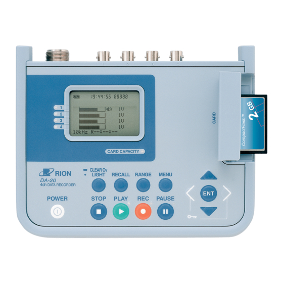
- Page 21 LCD screen Hours : Minutes : Seconds (1) Overload indicators (5) CARD CAPACITY indicator CARD CAPACITY CLEAR Ov LIGHT RECALL RANGE MENU DA-20 4ch DATA RECORDER POWER STOP PLAY PAUSE (4) PAUSE indicator (3) REC indicator (2) PLAY indicator Note...
-
Page 22: Rear Panel
12-V electrical system. If the CC-82 is used in a car with a 24-V electrical system to supply power to the DC IN connector of the DA-20, the unit will be damaged. (2) Remote Controller connector Serves to connect the Remote Controller (option). - Page 23 Parts and Functions (6) Input/Output connectors In modes other than recall mode, these connectors are used to supply the input signal for recording. While recorded data are being played back in recall mode, the playback signal is available at these connectors. Each connector therefore fulfi lls two functions.
-
Page 24: Front Side Panel
CompactFlash cards that contain other data fi les cannot be used in the DA-20. (The indication "Card Error" appears.) To use such a card in the DA-20, it must be formatted in the DA-20 fi rst. CompactFlash cards that use the FAT32 fi le format cannot be used in the DA-20. -
Page 25: Bottom Panel
When the [WAKE UP ON POWER] switch inside the battery compart- ment is set to "ON", the unit is switched on and off in conjunction with the power supplied to the DC IN connector on the DA-20. In this case, the [POWER] key has no effect. -
Page 26: Power On/Off
Power On/Off Turning the power on When you keep the [POWER] key depressed, the startup screen as shown below appears on the display. After a few seconds, the main screen will be shown. If there is a setting fi le on the CompactFlash card, the main screen does not appear straight away. - Page 27 Power On/Off Turning the power off When you keep the [POWER] key depressed, the shutdown screen as shown below appears on the display, and the unit is turned off. 1 0 m 1 4 : 0 6 : 3 1 0 0 0 0 9 S e e Y o u .
- Page 28 Power On/Off About the setting fi le You can store all setting values and parameters of the unit on the Compact- Flash card as a setting fi le (DA20.INI). This capability allows you for example to store the optimum settings for a certain recording task and then quickly re-establish these settings at power- on.
-
Page 29: Display Explanation
Display Explanation Display screen (1) Remaining battery capacity (3) Current time etc. (2) Recording time (4) Monitor channel (5) VP-80 connection channel (6) Index number 04:38:03 00008 Tr i g (17) Status indication (7) Key lock symbol 115dB (16) Trigger level 7 . - Page 30 (4) Monitor channel Indicates which channel signal is being supplied at the Monitor Out connector of the DA-20. The monitor channel can be changed with the [ ]/[ ] keys. (5) VP-80 connection channel Indicates which channel handles a signal supplied via the VP-80.
- Page 31 Display Explanation (8) Input range Shows the input range setting for each channel. The input range setting can be changed by using the [RANGE] key and other keys. (This is not possible during recording and in recall mode.) (9) Trigger information Indicates the setting of the "Trigger Mode"...
- Page 32 Display Explanation (11) Voice input setting Vo only Indicates the setting of the "Voice" item on Menu 2 < Rec.Parameters >. The "Voice" setting determines how the voice memo or marker function during recording is used. When the indication is " "...
- Page 33 Display Explanation (15) Overload history This indication is shown when there has been an overload condition be- tween the current point and a point in the past. To clear the overload history indication, hold down the [CLEAR Ov] key. (This key only affects the display. Any overload history information in recorded data is not deleted when the [CLEAR Ov] key is pressed.) The overload history is cleared in the following cases: ·...
- Page 34 Display Explanation (17-1) Basic operation status Shows the basic mode, such as recording, recall etc. No indication This is the condition when the main screen is shown. The menu screens, recording procedure, and recall mode are all accessed from this screen. This indicates the condition from the point where the re- cording operation is started (by pressing the [REC] key) to the end of the entire operation.
- Page 35 Display Explanation (17-3) Playback indication Shows the recorded data playback status in recall mode. Indicates that recorded data are being played back. The PLAY indicator next to the [PLAY] key also fl ash- Indicates that playback (processing) is carried out in fast-forward.
- Page 36 Display Explanation Data display formats The data display can be switched from bar graph mode to maximum data history for 0.5-second intervals. (In recall mode, this is not possible.) To switch between the bar graph and maximum data history display, use the [>] or [<] key.
-
Page 37: Menu Operations And Setting Items
Menu Operations and Setting Items General menu operation steps Almost all settings of the DA-20 except for the input range setting are made via menus. To make a setting, you call up the menu from the menu list page. When a menu has been selected, the screen with the individual settings of that menu appears. - Page 38 Menu Operations and Setting Items 3. Open the menu page Press the [ENT] key. The items on the selected menu page appear. 12/ 14 12 : 42 : 56 < I n p u t > C h I n p u t H P F L P F 1 : A C...
- Page 39 Menu Operations and Setting Items 6. Detailed explanation of methods A, B, C A: Change setting on sub menu 12/ 14 12 : 42 : 56 < I n p u t > Sub menu C h I n p u t H P F L P F 1 : A C...
- Page 40 Menu Operations and Setting Items The explanation below uses the channel 3 LPF setting on the < Input > page as an example. The procedure is the same for other items. A-1 Use the [ ]/[ ] keys to move the cursor in the sub menu to the desired setting.
- Page 41 Menu Operations and Setting Items If the desired setting does not appear on the sub menu Some sub menus have more settings than fi t into the sub menu frame. In such a case, a " " or " " is shown, indicating that you can bring up more settings by pressing the [ ] or [ ] key.
- Page 42 Menu Operations and Setting Items B-1 Use the [<]/[>] keys to move the sub cursor to the item you want to set (hours, minutes, or seconds in this example). T i m e : 4 8 : 3 6 Select setting item B-2 Use the [ ]/[ ] keys to change the value or unit of the item under the sub cursor (value for hours, minutes, or seconds in this example).
- Page 43 Menu Operations and Setting Items B-4' By pressing the [<] or [MENU] or [STOP] key instead of the [ENT] key, you can cancel the sub cursor operation without changing the setting. In this case, the indication is as shown below. MENU STOP T i m e...
- Page 44 Menu Operations and Setting Items 7. Changing an item on another menu page Press the [MENU] key to bring up the menu list. 12/ 20 10 : 48 : 17 MENU < M e n u L i s t > I n p u t R e c .
- Page 45 Menu Operations and Setting Items Menu fl ow diagram The organization of all menu operations is shown in the diagram below. Note that you always have to use the menu list to go to a menu page. Menu screen MENU Menu list STOP MENU...
-
Page 46: Menu Items
Menu Operations and Setting Items Menu Items Setting items are organized in six pages, with related items appearing together on one page. The menus are numbered from 1 to 6. The contents of each menu page are described below. Menu 1 < Input > Allows you to control input on/off, signal type, and fi lter settings for each channel. - Page 47 Menu Operations and Setting Items CCLD This setting is for microphones, accelerometers and other sensors that require a sensor drive power sup- ply. Select this setting when the input signal is supplied via the VP-80. This setting is available only for channels 1 to 3.
-
Page 48: Menu 2 < Rec.parameters
Sampling frequency setting (A: sub menu) By principle, the sampling frequency should be at least twice as high as the Freq.Range. The DA-20 provides a choice of two settings commonly used for frequency analyzers and voice processing: 2.4 times or 2.56 times the frequency range. - Page 49 Menu Operations and Setting Items Rec.Time Recording time setting (B: sub cursor) The recording time can be set in hours, minutes, or seconds, and a Manual setting is also available. When Manual is selected, the recording time is not predetermined, allowing the operator to press the [STOP] key whenever required.
- Page 50 When the switch is released, no signal (zero) is recorded. The voice memo setting has no effect when the DA-20 is not in record- ing mode. For details about the voice memo and marker function, see the section about auxiliary function setup (page 74) and the section about using the voice memo/marker (page 88).
-
Page 51: Menu 3 < Calibration
Menu Operations and Setting Items Menu 3 < Calibration > This menu comprises items related to the sensor type, sensitivity, units, etc. Menu 3 Sensor Sensor type setting (A: sub menu) Related to the "Input" item on Menu 1 < Input >, this item serves to select the actual sensor type. -
Page 52: Menu 4 < Trigger
Menu Operations and Setting Items Menu 4 < Trigger > Comprises trigger related items (see pages 66 to 72). 01/ 11 23 : 12 : 56 < Tr i g g e r > M o d e S i n g l e Ty p e : L e v e l L e v e l :... - Page 53 Menu Operations and Setting Items Type Trigger signal type setting (A: sub menu) Determines the type of trigger signal. When the "Mode" item is set to "Free", this item does not appear. Level A trigger event occurs and recording is started when the level of the input signal in the specifi ed channel (trigger channel) becomes higher than a preset value (trigger level).
-
Page 54: Menu 5 < System
Menu Operations and Setting Items Menu 5 < System > This menu comprises general items such as display contrast and Compact- Flash card formatting. Menu 5 Play Playback mode setting (A: sub menu) Determines whether the recorded data signal is supplied as a playback signal at the signal output connectors. - Page 55 DA-20. Be sure to use this menu item to format any card that you intend to use with the DA-20. When a format is performed in this way, a setting fi le created or updated with the "Save Settings"...
- Page 56 Menu Operations and Setting Items Light Auto Off LCD backlight timer setting (B: sub cursor) The LCD backlight is automatically turned off when there is no key activ- ity for a certain period. Available settings for this period are 10 seconds, 1 minute, 3 minutes, and CONT.
-
Page 57: Menu 6 < Date Time
The ID number can be set according to the system requirements. The setting range is 1 to 255. Because the ID number information is recorded along with the data, it can be used to identify multiple DA-20 units or data recording conditions. -
Page 58: Preparations
Preparations This chapter describes the settings and steps to take before starting to record data. Preparations and checks before recording 1. Power supply (inserting batteries, AC adapter, power-on mode) 2. CompactFlash card preparations (insertion and removal, format- ting) 3. Connection of external devices (sensors etc.) 4. -
Page 59: Preparations And Checks Before Recording
Preparations Preparations and checks before recording Power supply The DA-20 can be powered from four IEC R6 (size AA) alkaline batteries or from the optional AC adapter (NC-98 series). Inserting the batteries 1. Open the battery compartment cover. 2. Insert four IEC R6 (size AA) alkaline batteries with correct polarity, as shown inside the compartment. - Page 60 DC plug AC adapter (option) To grounded AC outlet (100 to 240 V) Important Use only the specifi ed AC adapter available as an option for the DA-20. Using another kind of AC adapter may lead to damage and malfunc- tion.
- Page 61 Preparations Power-on mode When you open the battery compartment cover as shown below, the [WAKE UP ON POWER] switch becomes accessible. By setting this switch to ON, you can have the on/off status of the unit controlled by the power supplied to the DC IN connector.
-
Page 62: Compactflash Card Preparations
Preparations CompactFlash card preparations Recorded data are saved on CompactFlash cards formatted in the DA-20, using the WAVE fi le format. To enable storing of recorded data fi les on a CompactFlash card, a special data management fi le and directory structure particular to the DA-20 is required on the card. - Page 63 Preparations 5. Verify that the following message is shown, and press the [ENT] key to proceed. To cancel the formatting process, press the [STOP] key. Card Format Delete all data. STOP Cancel 6. When the Menu 5 < System > screen is shown again, press the [STOP] key to return to the main screen.
- Page 64 Preparations Inserting and removing a CompactFlash card Turn power OFF and then proceed as shown below. Note Avoid inserting or removing a CompactFlash card while power is on. Slide card slot cover out Raise card slot cover Front side facing up CompactFlash card Push lever in to remove CompactFlash card...
-
Page 65: Sensor (External Equipment) Connections
Preparations Sensor (external equipment) connections The DA-20 is designed to handle the output of various sensors (including devices that use a sensor element to convert a physical quantity into an elec- trical signal). Correct input settings must be made, depending on the sensor and signal type and whether the sensor requires a constant current power supply. -
Page 66: Input Settings
Rion 3ch preamplifi er VP-80. The DA-20 can record up to four input signals simultaneously. These are handled by channels 1 to 4, each with its own input signal connector (1 to 4). - Page 67 Preparations CCLD For sensors requiring a constant current source For such sensors, a constant current is supplied via the input connectors of the DA-20. The physical quantity sensor in this case is limited to a microphone or accelerometer. Example 1:...
- Page 68 Preparations Sensitivity setting (Menu 3 < Calibration >: Sensor, Sensitivity) Sensor setting For AC or DC type sensors, the use of EU (Engineering Units) can be specifi ed. For CCLD type sensors, the physical quantity detection element can be specifi ed as being a microphone or accelerometer. When the Input setting and the Sensor setting have been made, the sensor signal unit will automatically be set.
- Page 69 Preparations Set the microphone sensitivity level. Example: For UC-53A rated for -28 dB and used together with NH-22, the transmission loss is taken as -0.8 dB and the setting should therefore be "-28.8". Set the physical quantity corresponding to a sensor signal voltage of 1 V.
- Page 70 Preparations The table below shows the correlation formula for the original input range X [V] and the condition after the sensitivity setting. Input range value Unit Sensitivity value Sensor type after conversion X [V] None DC/AC (---) K × X [EU] K[EU/V] DC/AC (EU)
- Page 71 Preparations Input settings and sensitivity settings for some representative sensors are shown below for reference. The sensitivity value differs for each sensor. (For channels where "Input" is set to "DC", the input range cannot be lower than 1 V.) Sensor sensitivity Sensor example Input Sensor...
- Page 72 To make connections for a VP-80 and piezoelectric accelerometer, turn power to the DA-20 off and then perform the following steps. 1. Attach the 3ch preamplifi er VP-80 to the DA-20. If an extension is required, the extension cable EC-04 or similar can be used.
-
Page 73: Calendar (Menu 6 < Date Time >: Date, Time)
(On screens other than Menu 6, the year or the month/day are not shown.) The DA-20 will operate even if the date and time have not been set, but the following message will appear at startup and every time when starting to record. -
Page 74: Recording Parameter Settings
The input range can be set in 7 steps (0.01, 0.03, 0.1, 0.3, 1, 3, 10 V). Select an appropriate setting according to the input signal level and the operation method of the DA-20. For improved S/N ratio, setting the input range as low as possible without causing overload is generally preferred. - Page 75 Preparations 3. Activate the range change mode Press the [ENT] key to allow changing the cur- rent input range setting. Verify that the cursor fl ashes. 115dB 7. 2E + 3 1. 6E + 2 4. Select the new input range setting. Use the [ ]/[ ] keys to change the input range.
- Page 76 Preparations Input range setting and overload In step 4, set the input range while checking whether overload occurs. When this happens, the overload indicator lights up in red, and the indi- cation appears on the display. To improve reliability and ensure that overload does not occur for an extended period, the overload history indication is convenient.
-
Page 77: Sampling
Preparations Sampling The sampling action of the DA-20 is controlled by the frequency range and sampling frequency setting. The sampling frequency can be set to 2.4 times or 2.56 times the frequency range. Setting the frequency range The frequency range can be set in 6 steps (100 Hz, 500 Hz, 1 kHz, 5 kHz, 10 kHz, 20 kHz). -
Page 78: Recording Process
Preparations Recording process When you press the [REC] key, the data recording operation starts. However, if the trigger function (described later) is used, recording may not begin right away. In such a case, actual recording will only start when the trigger condi- tions are met, or in other words when a trigger event occurs. - Page 79 < Rec.Parameters >. The recording time setting cannot exceed the remaining available capacity of the CompactFlash card inserted in the DA-20. If this applies, the recording time will automatically be changed to the maximum available time at the point where the [ENT] key is pressed.
- Page 80 Preparations Setting the pre-time If you wish to include data from a point slightly before the [REC] key was pressed, use the pre-time function. The three available pre-time settings are 0, 1, and 5 seconds. The pre-time function also works in conjunction with the trigger function (described later).
- Page 81 When the trigger type is set to "Level", the trigger level and trigger channel must be set. Only trigger events that occur while the DA-20 is in the trigger standby condition are valid. Any trigger events that occur while data record- ing is in progress are disregarded.
- Page 82 Preparations Recording procedure Data recording in progress Free Recording procedure Trigger Data recording in progress standby Single Recording procedure Trigger Trigger Data recording in progress Data recording in progress standby standby Repeat During data recording, trigger event is disregarded. Trigger events Difference in recording procedure according to trigger mode (Pre-time setting 0, recording time setting not Manual, trigger type not External Gate)
- Page 83 Preparations Setting the trigger type This setting determines the type of event that serves as a trigger. Make the setting using the "Type" item in Menu 4 < Trigger >. Level (level trigger) A trigger event occurs when the level of the input signal in the specifi ed channel (trigger channel) becomes higher than a preset value (trigger level).
- Page 84 Preparations Setting the trigger level When the trigger type is set to "Level" (level of signal at input connector), the actual level to be used as a trigger level must be set as a percentage [%] of the full-scale value of the current input range. Make the setting using the "Level"...
-
Page 85: Auxiliary Function Setup
Some possible uses for the ID number capability are listed below. 1. Temporary management (classifi cation) of recorded data Example 1 In a system where several DA-20 units are used, the ID number can serve to manage data according to the unit on which the data were recorded. -
Page 86: Voice Memo/Marker
Preparations Voice memo/marker The voice memo function allows the operator to add comments before and after the recording procedure or during recording. The marker function can be used to mark a certain position, for example when a particular phenom- enon occurred during recording. This makes it easy to later locate the data for that point. - Page 87 Preparations OFF (Marker) The voice memo function is not used. Marker information can be recorded. The "Voice Only" or "Voice/Input" setting can only be selected when the frequency range setting is 1 kHz or higher. Marker The marker function is only available during data recording. Marker recording does not affect the operation of channel 4.
- Page 88 Preparations Comparison of voice memo and marker operation The diagram below illustrates the operation principle of the voice memo and marker function. The functions differ in the action that occurs when the microphone switch is pressed. Recording start Voice memo Voice memo Voice memo Voice Only...
-
Page 89: Preventing Inadvertent Operation
Preparations Preventing inadvertent operation This section explains the key lock and menu lock functions that serve to prevent operation errors when performing data recording in the fi eld. Key lock Makes almost all keys inactive Pressing and holding the [<] and [>] keys together for a few seconds activates the key lock condition. -
Page 90: Remote Control Operation
DA-20 used to record data under a given set of conditions. Because the Remote Controller is designed to be operative also when the key lock feature is enabled, the DA-20 can be protected from inadvertent operation. - Page 91 Preparations The fi rst push of the [START/STOP] switch on the Remote Controller starts recording. When the switch is pushed while recording is in progress, record- ing stops. The operation status indicator provides the information listed in the following table. Status indicator Operation Flashing red...
-
Page 92: Recording
If the sensitivity setting of the DA-20 can be considered to provide suffi cient accuracy, recording a calibration signal is not necessary. 3. Recording Use the [REC] key to perform the recording procedure, and repeat as necessary. - Page 93 Controller. Is ID number setting appropriate? (See page 73) 3. CompactFlash card Is CompactFlash card appropriate for use in DA-20? (Insert card and check for messages.) (See page 109, 111) Is enough free capacity available? Is spare CompactFlash card available? (Set number of channels and recording parameters as required, and then check remaining recording time on main screen.) (See page 8)
-
Page 94: Input Range Setting / Calibration Signal Recording
Recording 2. Input range setting / Calibration signal recording Changing the input range setting 1. Press the [RANGE] key to cause the input range display section to be shown in reverse (cursor active). 2. Use the [ ]/[ ] keys to move the cursor to the channel whose input range setting you want to change. - Page 95 In actual use, the operator should decide whether calibration is necessary, based on information given in this manual and other data. 1. Sensor input range setting (not input range setting of DA-20) was changed. In this case, the same measurement quantity input may result in a different output signal being supplied to the DA-20.
-
Page 96: Recording
Recording can be started in this condition. [Card Error. Remove or format card.] A CompactFlash card that cannot be used in the DA-20 was inserted. Press any key to cancel the message. Any [REC] key operation is disregarded. - Page 97 Recording When does the recording procedure stop? The recording procedure stops in the following cases. When the recording time setting is "Manual" or when the trigger mode setting is "Repeat", the recording procedure stops only in cases 2 and 3. 1.
- Page 98 Recording Terminating a recording partway Press the [STOP] key. The REC indicator and the indication go out and STOP recording stops. Now Closing fi le. Do not remove Card. While the above message is shown, do not remove the CompactFlash card, because data are being written to it.
- Page 99 Recording Recording procedure conditions and indicator/display status The various conditions of the unit during the recording procedure can be checked using the indicators and the LCD panel. The two illustrations below show the various conditions, with and without the use of the trigger function. (Flashing of an indicator or symbol is indicated in the illustration as PAUSE PAUSE...
-
Page 100: Using The Voice Memo/Marker Function
Recording Using the voice memo/marker function Voice memo Voice memo recording starts when the microphone switch is pushed and stops when the switch is released. While recording a voice memo, the indication VOICE is shown on the bar graph for channel 4. Microphone 0. - Page 101 Recording Marker When the microphone switch is pressed while data are being recorded, the current time is recorded as a marker. Pressing the switch also causes the indication MARKER to appear on the bar graph for channel 4 for about one second.
- Page 102 Recording PAUSE PAUSE Recording start Recording Pause Recording in progress in progress Voice No signal No signal (zero) Voice memo No signal (zero) memo Voice Only (zero) Voice Input4 Input4 Voice memo Input4 Voice/Input memo Voice memo OFF(Marker) This time Released point is recorded Microphone...
- Page 103 Recording Trigger event Recording of data corresponding PAUSE PAUSE PAUSE PAUSE to recording time is completed Recording start Trigger Trigger Trigger Recording Recording in progress standby Pause standby in progress standby paused Voice No signal No signal Voice No signal Voice memo Voice Only...
-
Page 104: Data Recording Example
Connect the comparator output of the sound level meter to the Ext. Trig. con- nector of the DA-20, using the cable CC-94A. Connect the AC output of the sound level meter to the signal input connector 1 of the DA-20. - Page 105 Comparator CC-24S output cable (CC-24 can also be used) CC-94A To Ext. Trig. connector To signal input connector 1 To Voice Input connector DA-20 Generated file name D00005 (Trigger1) D00006 (Trigger2) D00007 (Trigger3) Recorded sound pressure waveform (channel 1) Voice memo...
-
Page 106: Recall/Playback Of Recorded Data
Recall/Playback of Recorded Data You can call up a list of recorded data and select data for playback and for checking. You can also delete unwanted data or determine whether data have to be recorded again. Activating recall mode Press the [RECALL] key. A screen listing recorded data appears, and the unit is switched to recall mode. - Page 107 Recall/Playback of Recorded Data 2. If no CompactFlash card is inserted The recall mode cannot be activated. In this case, the indication No Card!! fl ashes on the display for a few seconds, and then the main screen appears again. 3.
- Page 108 Recall/Playback of Recorded Data Making a rough check of recorded data On the recorded data list screen, the recording start time, recording time, and index number for the data selected by the cursor are shown. The "XXXXX" of "DXXXXX" corresponds to the index number. The recording time shown is the actual recording time of the data.
- Page 109 Recall/Playback of Recorded Data Selecting recorded data for playback Move the cursor to the recorded data you want to play back, and press the [ENT] key. The recall screen appears, and the recorded data can be played back. BNC output Recording time Index number 00:00:00 00007 Recal l B N C...
- Page 110 Recall/Playback of Recorded Data Important If the playback signal is applied to a sensor, the sensor may be destroyed. When the output set- ting for the playback signal is "BNC", disconnect all sensors before starting playback.
-
Page 111: Playback Of Recorded Data
Recall/Playback of Recorded Data Playback of recorded data The recall screen gives access to various operations related to playback of recorded data. Playing recorded data Press the [PLAY] key. Playback of recorded data starts. During playback, the PLAY indicator at the top right PLAY of the [PLAY] key fl ashes, and the playback symbol appears on the display. - Page 112 Recall/Playback of Recorded Data Stopping playback partway Press the [STOP] key. STOP The PLAY indicator and playback symbol go out, and the unit returns to the recall screen. STOP Recording time 12345 Elapsed playback time 12345 Recall Recall B N C Pausing and restarting playback Press the [PAUSE] key.
- Page 113 Recall/Playback of Recorded Data Performing fast forward or reverse during playback Press the [>]/[<] keys. While you press the [>] or [<] key, the playback position is moved quickly forwards or backwards. During this time, no playback signal is output. If the playback posi- tion was moved all the way to the end of the recorded data, playback will stop when you release the [>] key.
- Page 114 Recall/Playback of Recorded Data High-speed forward or reverse Press and hold the [>]/[<] keys during playback pause. When you press and hold the [>] or [<] key for more than 1 second, the playback position is moved at high speed forwards or backwards. When you release the key, the unit again goes into the playback pause condi- tion.
-
Page 115: Canceling Recall Mode
Recall/Playback of Recorded Data Canceling recall mode When you press the [RECALL] key at the data list screen, the recall mode is terminated and the unit returns to the main screen. If a recall screen is currently shown, press the [RECALL] key once to return to the data list screen, and then press it again to cancel the recall mode. -
Page 116: Other Information
Recall/Playback of Recorded Data Other information When CompactFlash card was removed in recall mode While the unit is in recall mode, you should not remove the CompactFlash card. If the CompactFlash card is removed, the following message appears. NO Card Insert Card or Press Go to Main... - Page 117 The supplied viewer software allows you to read this fi le, edit the settings, and write the fi le to the CompactFlash card for use in the DA-20. You can also store the fi le on a different location in the computer, and use suitable...
- Page 118 Recall/Playback of Recorded Data R e c a l l m o d e Recorded data list screen RANGE RECALL Delete recorded Change index data with highest number index number Ensure proper RECALL match between CCLD setting and sensor type Recall screen Change index number...
-
Page 119: Messages
Messages During operation of this unit, various messages giving warnings and providing procedure information will appear. The most important messages are listed and described in this section. (The actual font and placement of the message on the display may differ from the examples shown here.) Messages are listed below in alphabetical order. - Page 120 Messages The message explanation uses the following pattern. Message string Description Explains the meaning of the message or the condition it refers to. Countermeasure Describes steps to take when the message is shown. Condition Describes the operation steps or unit condition that can lead to the message being shown.
- Page 121 Folder/fi le structure as required by the DA-20 is not present, or another folder/fi le structure exists. There has been an error managing a fi le required by the DA-20. The card was formatted using a fi le system other than FAT16, or the card is defective.
- Page 122 Description At power-on, the unit attempted to load settings from a setting fi le, but an error or setting problem was detected. The problem could be setting values that are out of range for the DA-20 or contradictory settings. Countermeasure Press the [ENT] key.
- Page 123 CompactFlash card will be retained.) Copy the existing data (fi les) from the CompactFlash card to a computer or similar and then format the card in the DA-20 again. Alternatively, use a different CompactFlash card.
- Page 124 Messages Card Format. Delete all data. [ENT] Card Format. Now formatting... Cancel STOP Description Confi rmation of CompactFlash card formatting process Countermeasure Press the [ENT] key to format, [STOP] key to cancel. Condition Executing "Card Format" item of Menu 5 < System > CCLD PW Checking Please wait...
- Page 125 Countermeasure Press any key to cancel the message. The DA-20 can be used in this condition. If the recording start time as used by the unit does not need to match the actual time, no setting is required. Otherwise make the setting with Menu 6 <...
- Page 126 Messages Low Battery Shutdown in XX sec. Description Battery voltage has fallen below required level. The unit will auto- matically turn itself off after a countdown of 60 seconds. Countermeasure Supply external power before the countdown fi nishes. (If the countdown fi nishes and the unit shuts down while recording was in progress, the data up to that point will be saved on the Com- pactFlash card.) Menu Lock !
- Page 127 Never remove the CompactFlash card in this condition. Be sure to wait until the message has disappeared. Otherwise the card may become unusable until formatted in the DA-20 again (at this time, previously recorded data will also be destroyed). While the message is being shown, the [REC] key is inactive and any trigger event is disregarded.
- Page 128 Messages Resume CCLD? [ENT] CCLD PW Checking Please wait...VV No(inactivate) STOP Cancel PAUSE Description This is a confi rmation whether it is alright to supply a constant current to a signal input connector set to CCLD (for sensor protection). Countermeasure To maintain the CCLD setting, press the [ENT] key.
- Page 129 If no setting fi le is found, this message does not appear. Countermeasure Press the [ENT] key to set up the DA-20 according to the setting fi le content. Press the [STOP] key to use the settings that were active before power was last switched off.
-
Page 130: Filter Characteristics
Filter Characteristics Representative low-pass fi lter and high-pass fi lter characteristics are shown below. The available low-pass fi lter settings are OFF, 100 Hz, 500 Hz, and 1 kHz, but the setting must be lower than the frequency range setting. When the OFF setting is selected, the low-pass fi lter is set to the cutoff frequency of the frequency range (anti-aliasing fi lter). -
Page 131: Backup Battery
The DA-20 incorporates a backup battery (rechargeable) for clock data backup. The battery is recharged automatically while power to the DA-20 is on. It takes about 12 hours to reach a full charge. With a full charge, data will be retained for about 1.5 months. If this period is exceeded, clock data will be lost. -
Page 132: Specifi Cations
Specifi cations Input section Number of channels Input connectors Signal input BNC × 4 Voice memo input 4-pole mini jack × 1 External trigger input stereo mini jack × 1 (used in monaural confi guration) 3ch preamplifi er (VP-80) input 7-pin connector ×... - Page 133 Specifi cations Inter-channel phase lag 4 deg max. (same range, AC coupling, HPF OFF, fre- quency range 1 Hz to 20 kHz) Frequency response DC coupling DC to 1 Hz ±1.0 dB 1 Hz to 12.5 kHz ±0.5 dB 12.5 kHz to 20 kHz ±1.0 dB AC coupling 1 Hz ±1.0 dB...
- Page 134 Specifi cations Playback output Playback output connectors Output impedance 600 Ω Frequency response DC to 1 Hz ±1.0 dB 1 Hz to 12.5 kHz ±0.5 dB 12.5 kHz to 20 kHz ±1.0 dB Output voltage ±3.16 V (corresponding voltage at range full-scale) Maximum output voltage ±4.0 V Monitor output connector...
- Page 135 Specifi cations Recording section Recording media CompactFlash card (Type I), operation assured with Rion-supplied cards only (128 MB, 256 MB, 1 GB, 2 GB) File system FAT 16 A/D converter 16-bit quantization File format WAVE (16-bit linear, non-compression) Frequency range settings...
- Page 136 Specifi cations Display LCD panel 128 × 64 dots, 121 segments (with backlight) Display contents Setting screen, recording screen, level bar graph, level history. LED indicators Overload indication for each channel, remaining card capacity warning. Status indicator for recording, playback, trigger standby, etc.
- Page 137 Specifi cations Supplied accessories IEC R6 (size AA) battery (alkaline) (LR6) Viewer software (DA-20 Viewer CD-ROM) Soft carrying case (DA-20-007) Shoulder strap (VX-54-003) (included in the soft carrying case) Voice memo microphone Monitor earphone Instruction manual Inspection certifi cate Optional accessories...
- Page 138 Specifi cations Top view CARD CAPACITY CLEAR OV DELETE LIGHT RECALL RANGE MENU DA-20 4ch DATA RECORDER POWER STOP PLAY PAUSE Front view Side view Unit: mm Dimensional drawing of 4-Channel Data Recorder DA-20...
- Page 140 No. 40753 09-09...
Need help?
Do you have a question about the DA-20 and is the answer not in the manual?
Questions and answers