
Related Manuals for Miranda NV5256


Summary of Contents for Miranda NV5256
- Page 1 NV5256 Machine Control Router User’s Guide Miranda Technologies Inc. 3499 Douglas B. Floreani Montreal, Quebec Canada H4S 2C6...
- Page 2 The information and intellectual property contained herein is confidential between Miranda and the client and remains the exclusive property of Miranda. If you find any problems in the documentation, please report them to us in writing. Miranda does not warrant that this document is error-free.
- Page 3 Contact Miranda for details on the software license agreement and product warranty. Technical Support Contact Information Miranda has made every effort to ensure that the equipment you receive is in perfect working order and that the equipment fits your needs. In the event that problems arise that you cannot resolve, or...
- Page 4 D.Cox Restriction on Hazardous Substances (RoHS) Miranda is in compliance with EU Directive RoHS 2002/95/EC governing the restricted use of cer- tain hazardous substances and materials in products and in our manufacturing processes. Miranda has a substantial program in place for RoHS compliance that includes significant invest- ment in our manufacturing process, and a migration of Miranda product electronic components and structural materials to RoHS compliance.
- Page 5 The fuse symbol indicates that the fuse referenced in the text must be replaced with one having the ratings indicated. The presence of this symbol in or on Miranda equipment means that it has been designed, tested and certified as complying with applicable Underwriter’s Laboratory (USA) regulations and rec- ommendations.
- Page 6 General Warnings A warning indicates a possible hazard to personnel which may cause injury or death. Observe the following general warnings when using or working on this equipment: • Heed all warnings on the unit and in the operating instructions. •...
-
Page 7: Table Of Contents
Power Supply Alarms ............18 NV5256 Machine Control Router • User’s Guide... - Page 8 Table of Contents Power ............... 18 Connectors .
-
Page 9: Preface
1. Preface Chapter 1 provides an introduction to the NV5256 User’s Guide. It presents the following topics: • Chapter Structure • The PDF Document • Terms, Conventions and Abbreviations Chapter Structure The following chapters provide information regarding the NV5256 Machine Control Router: •... -
Page 10: Terms, Conventions And Abbreviations
• Press ‘Keyer 2’ button ... The following terms and abbreviations are used throughout this guide: • The term “router” refers to the NV5256 machine control router, unless it used in a broader con- text such as “NV9000 Router Control System.”... -
Page 11: Introduction
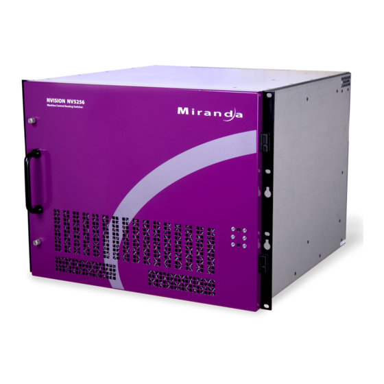
• All control panels properly configured. Overview The NV5256 is a machine control router — a successor to the NV3256. A machine control router transmits control messages and responses between devices such as VTRs and edit stations. Physically, the NV5256 has an 8RU frame that holds the following items: •... - Page 12 Cards (2) Control Card (diagn. port) Empty Control Card Slot Port I/O Cards (16) Power Supply Module Power Supply Module Figure 2-1. NV5256, Front View Primary Control Redundant Control Card Ports Card Ports Serial Control Ports Diagnostic Ports Expansion AES Ref.
-
Page 13: I/O Signals
The Tx-to-Rx connection, of course, depends on the cable. Straight-through cables are consid- ered preferable. Router Configuration The NV5256 router has several configurable options. It supports several signal options that can be configured for each port. The router can be (and must be) configured to operate according to your system constraints. You will need to specify the size of the router matrix, the type of ports, communication parameters, and so on. -
Page 14: Router Expansion
Router Expansion Two NV5256 frames can be connected to create an expanded router. Six expansion ports are at the top right at the rear of the router. There are 6 BNC connections — 3 coming in and 3 going out. -
Page 15: Sms7000
Functions The NV5256 router can be configured with partitions of 4 types. Each partition is considered a physical level. The physical levels can be of 4 “signal types.” The signal types accommodate the different characteristics of Miranda’s NVISION series routers and third-party routers. -
Page 16: Machine Control Broadcast
Any dynamic port connected to a “master” port will be a controlled port. The NV5256 applies logic to the port direction setting when a master port is connected to a dynamic port. In this case, the machine at the dynamic port is always controlled and the machine at the master port is always controlling. -
Page 17: Summary
In general, a controlling machine must connect, through the router, to a controlled machine. That is because Tx must connect to Rx and vice versa. In NV9000-SE Utilities, when you add the NV5256 router to your system, set ‘Signal Type’ to ‘Machine Control’. Also set both ‘Output Protect’ and ‘Output Lock’ to ‘In Server’. - Page 18 Warning: Disconnect power, if it is connected, before mounting the frame in the rack. Warning: The NV5256 draws cooling air from the front through the door and exhausts it at the top rear edge of the frame. Make certain that airflow is not blocked at these locations. If air flow is restricted, overheating may occur.
-
Page 19: Detail
3. Detail Chapter 3 describes the structure and use of the NV5256 Machine Control Router. It presents the following topics: • Connections • Alarms • Power • I/O Cables • Port Cards • Expansion • Terminators • Jumpers Connections The rear of the router has a bay that holds up to 16 I/O backplanes. Unused backplane slots are gen- erally covered with a plate that improves cooling air flow. -
Page 20: Control Ports
3. Detail Connections Control Ports At the top left portion of the rear of the NV5256 frame are 6 DE9 connectors, and further below that are 2 Ethernet connectors: for Primary for Secondary Control Card Control Card PRI CTRL SEC CTRL... -
Page 21: Ethernet Control
1 Supply an AES reference to the primary control card of both frames. You can use either connec- tor. If you have a secondary control card, supply an AES reference to that also. Use the connectors at the top left portion at the rear of the NV5256 frame: for Primary... -
Page 22: Inter-Frame Communication
If the frames in an expanded router are not clock-locked, data errors will occur when the router uses ports across frame boundaries. Inter-Frame Communication At the top left portion of the rear of the NV5256 frame are two 10Base2 (BNC) connectors: for Primary for Secondary... -
Page 23: Aux Bus
50Ω terminators on both connectors. In any expanded router, place 50Ω terminators on unused 10Base2 connectors. Aux Bus At the middle left portion of the rear of the NV5256 frame are 2 ‘NVISION Aux Bus’ (BNC) con- nectors: 10/100 BT... -
Page 24: Time Code Reference
If you have an expanded router, use the loop-through connector to connect the master and slave frames. Terminate any reference chains with 75Ω terminators. Time Code Reference At the lower left portion of the rear of the NV5256 frame are 2 connectors for time-code reference: ALARMS Time-Code... - Page 25 CAUTION: If the alarm load is inductive, protect the internal alarm relay contacts with a reversed- biased diode. The external supply voltage should not exceed ±30VDC and the load resistors should be sized to limit contact current to less than 150mA. NV5256 Machine Control Router • User’s Guide...
-
Page 26: Power Supply Alarms
3. Detail Power Power Supply Alarms At the lower right portion of the rear of the NV5256 frame is a Phoenix 3-pin connector for power supply alarms: TO REDUCE THE RISK OF ELECTRIC SHOCK, DISCONNECT TWO POWER SUPPLY CORDS BEFORE SERVICING. -
Page 27: Connectors
3. Detail Power Connectors At the middle right portion of the rear of the NV5256 frame are 2 AC connectors: PS 1 LEFT AC connector for PS 1 PLEASE READ INSTRUCTION PS 2 MANUAL BEFORE CONNECTING RIGHT EQUIPMENT TO THE MAINS... -
Page 28: Ground Lug
PROFESSIONAL VIDEO/AUDIO Connect this “lug” to earth ground using 8–14 AWG wire. Expansion Connectors At the top right portion of the rear of the NV5256 frame are 6 Expansion (BNC) connectors: FUSES LOCATED ON POWER SUPPLIES T 8.0A 250V FOR 90-130V~ T 6.3A 250V... -
Page 29: Breakout Panel
If you are using the BP-PORT-64 breakout panel, you might need to know the mapping of the sig- nals from the RJ-45 side to the 9-pin (female) side. The breakout panel is RS-422/485 only. See Breakout Panel on page 6 for an illustration. NV5256 Machine Control Router • User’s Guide... -
Page 30: Rs-232 Cables
Any DE9-to-DE9 cables you might use will be straight-through. Port Cards The NV5256 has slots for 16 port I/O cards. Each card supports 16 inputs from its corresponding backplane. There are two types of port cards: • The EM0503-01 module, supporting RS-422/485. -
Page 31: Expansion
Expansion The NV5256 can be expanded to a maximum of 512 ports. To accomplish this, interconnect two NV5256 frames. The frames share each other’s input space. The first frame receives commands from the router control system and acts as the master to the second frame. -
Page 32: The Expansion Card
You can use 75Ω Belden 8281 cable, up to 250 meters, to make these connections. The Expansion Card The NV5256 has 2 slots for expansion cards. A stand-alone router requires no expansion card. One card is required for expansion. The second expansion card provides redundancy. -
Page 33: Terminators
50Ω terminator on each unused 10Base2 connector. Terminators 10Base2 The NV5256 ships with two 50Ω terminators for each frame. The terminators are required for an expanded router. In older routers, termination for a stand-alone router is required. In newer routers, it is not. -
Page 34: Jumpers
AESREF1 SBUS PC0436–02 AESREF2 AESREF1 Figure 3-5. EM0374 Router Control Card Jumpers Table 3-2 describes the jumpers appropriate to the NV5256. Jumpers not listed should be left in the factory position: Table 3-2. EM0374 Jumpers Jumper Settings J1, J2 Frame-to-frame communication. Leave these jumpers in the 10B2 position. The control card (and therefore the NV5256) does not support SBus yet. -
Page 35: Configuration
4. Configuration Chapter 4 describes the structure and use of the NV5256 Machine Control Router. It presents the following topics: • Summary • UniConfig—Stage 1 • UniConfig—Stage 2 Summary There are several phases to configuring an NV5256 router. 1 Use UniConfig (first) to define its network address and (second) to define its basic partitions and specify its port types. - Page 36 Specify your PC’s COM port. Choose 9600 for the Baud rate. 4 From the Windows menu, choose ‘Configuration’. The following window appears: Click ‘Read All’ to obtain the NV5256 parameters and the router control card’s software and firmware versions. Rev 1.7 • 18 Aug 10...
- Page 37 Asterisks (*) indicate which modules are in effect. (APP1 should indicate that it is an NV5256 application. PLD0 should indicate that it is an NV5256 PLD.) 6 Enter the IP address for this NV5256 control card. Also enter the IP subnet mask. The mask should always be 255.255.255.0. Make sure Ethernet control is enabled.
-
Page 38: Uniconfig-Stage 2
11 When everything is correct, click ‘Write All’ (next to ‘Read All’) to send the configuration data to the NV5256. Now the router control card has its IP address and its basic partitioning. 12 Repeat this entire process for each router control card in each NV5256 frame. The redundant control card in any frame should be configured the same as the primary control card. - Page 39 8 for information on port types. 4 Click the ‘Write’ button at any time to send the port type definitions to the NV5256. 5 The ‘Machine Control Port Setup’ window also has an option where you can specify the take delay: NV5256 Machine Control Router •...
-
Page 40: Perform Takes In Uniconfig
1 Launch UniConfig. If your installation permits, choose ‘Ethernet’ from the Communications menu. Otherwise, use a serial connection. Select and read the NV5256 configuration. 2 Choose ‘Connections’ from Window menu: Click ‘Read Outputs’ to obtain the current crosspoint status. You can specify the range of out- puts to read. -
Page 41: Other
If the ports’ physical level were designated machine control forward, port 3 (the output) would be the controlled device, and port 10 (the input) would be the controlling device. 4 It is not possible to write any of this to the NV5256 control card, because these takes are not part of its configuration. - Page 42 4. Configuration UniConfig—Stage 2 Rev 1.7 • 18 Aug 10...
-
Page 43: Maintenance
Only qualified service personnel should perform procedures in this section. Caution Periodic Inspection Periodically inspecting the NV5256 for signs of trouble is the best way to prevent unplanned out- ages. Begin the inspection at the front of the frame. Open the door to the matrix and make these observations. -
Page 44: Intake Air Filter Cleaning
Intake Air Filter Cleaning The air intake filter is located on the front door assembly of the NV5256. Slide the filter up and to the right to remove it. The process might be easier if you remove the entire door. To remove the door, simply open the door and lift it straight up. -
Page 45: Fuse Replacement
Please contact Miranda for assistance if a fault cannot be isolated. NV5256 Machine Control Router • User’s Guide... -
Page 46: Led Status Indicators
5. Maintenance LED Status Indicators Figure 5-2 shows the location of the fuse on either power supply module. Fuse 2 5 0 V Figure 5-2. Fuse Location, PS6000 or PS6100 Power Supply LED Status Indicators Each I/O card has status indicators (LEDs). Table 5-1 lists the control card’s main LEDs: Table 5-1. -
Page 47: Specifications
6. Specifications Chapter 6 provides specifications for the NV5256. It presents the following topics: • Electrical Specifications • Mechanical Specifications • Environmental Specifications • I/O Card Specifications • Expansion Card Specifications • Communication Port Specifications • Reference Port Specifications Electrical Specifications Table 6-1. -
Page 48: Environmental Specifications
Table 6-3. Environmental Requirements for the NV5256 Parameter Specification Operating temperature 0–40°C (32–104°F) Humidity 0–90%, non-condensing I/O Card Specifications Table 6-4. I/O Card Specifications for the NV5256 Parameter Specification Ports per card Input voltage 200 mV to 10 V p-p Output voltage RS-422: 5V p-p. -
Page 49: Communication Port Specifications
6. Specifications Communication Port Specifications Communication Port Specifications Table 6-6. Communications Port and Related Specifications for the NV5256 Parameter Specification Serial communication One primary DE9 female (CTRL1) and one secondary DE9 female (CTRL2) RS- ports 422 receptacles for each control card (4 in total). - Page 50 6. Specifications Reference Port Specifications Rev 1.7 • 18 Aug 10...
-
Page 51: Misc. Topics
There are two sets of AES reference connectors, one for the primary control card and one for the secondary control card. You can use either the BNC connector or the Phoenix 3-pin STP connec- tors. This figure shows the pinouts of the Phoenix connectors: PRI CTRL SEC CTRL NV5256 Machine Control Router • User’s Guide... -
Page 52: Ordering Information
7. Misc. Topics Ordering Information Ordering Information These are the NV5256 components: FR0007-00 NV5256 frame EM0501 NV5256 motherboard EM0405 Power distribution EM0407 Power interconnect EM0503-01 RS-422 I/O card EM0503-50 RS-232 I/O card EM0502 Expansion card EM0483 I/O backplane BP2-PORT-64 64-Port RJ-45-to-DE9 Breakout Panel (FR0008-00) -
Page 53: Index
....... iii port specifications, NV5256 ....41 shipping . - Page 54 EM0503-01 ......22, 44 I/O card specifications, NV5256 ... . . 40 EM0503-50 .
- Page 55 ......iii NV5256, rear view ..... . 4 technical support .
- Page 56 ..... .2 Website, Miranda ......iii System alarms .
Need help?
Do you have a question about the NV5256 and is the answer not in the manual?
Questions and answers