Table of Contents
Advertisement
2
nd
PRINTING
June 2017
Sega Amusements International Limited.
42 Barwell Business Park, Leatherhead Road, Chessington, Surrey, KT9 2NY. United Kingdom.
Telephone: +44 (0) 208 391 8090
Facsimile:
+44 (0) 208 391 8099
email: mailbox@sega.co.uk
Web: http://www.segaarcade.com
Sega Games Co,. Ltd.
1-2-12, Haneda, Ota-ku, Tokyo, 144-8531. Japan.
Telephone: +81-3-5736-7111
Facsimile:
+81-3-6871-7672
sega-games.co.jp
© SEGA
Errors and omissions excepted (E&OE)
IMPORTANT
• Before using this product, read this manual carefully to understand the
contents herein stated.
• After reading this manual, be sure to keep it near the product or in a
convenient place for easy reference when necessary.
Advertisement
Table of Contents

Related Manuals for Sega Let's Go Island


Summary of Contents for Sega Let's Go Island
- Page 1 PRINTING June 2017 Sega Amusements International Limited. 42 Barwell Business Park, Leatherhead Road, Chessington, Surrey, KT9 2NY. United Kingdom. Telephone: +44 (0) 208 391 8090 Facsimile: +44 (0) 208 391 8099 email: mailbox@sega.co.uk Web: http://www.segaarcade.com Sega Games Co,. Ltd. 1-2-12, Haneda, Ota-ku, Tokyo, 144-8531. Japan.
- Page 2 BEFORE USING THE PRODUCT , BE SURE TO READ THE FOLLOWING: To maintain safety: To ensure the safe operation of this product, be sure to read the following before usage. The following instructions are intended for the users, operators and the personnel in charge of the operation of the product.
- Page 3 INSPECTIONS IMMEDIATELY AFTER TRANSPORTING THE PRODUCT TO THE LOCATION Normally, at the time of shipment, SEGA products are in a status allowing for usage immediately after transporting to the location. Nevertheless, an irregular situation may occur during transportation. Before turning on the power, check the following points to ensure that the product has been transported in a satisfactory status.
-
Page 4: Table Of Contents
TABLE OF CONTENTS INTRODUCTION HANDLING PRECAUTIONS PRECAUTIONS REGARDING INSTALLATION LOCATION 2-1 LIMITATIONS OF USAGE 2-2 OPERATION AREA PRECAUTIONS REGARDING PRODUCT OPERATION 3-1 BEFORE OPERATION 3-2 DURING OPERATION (PAYING ATTENTION TO CUSTOMERS) PART DESCRIPTIONS ACCESSORIES ASSEMBLY AND INSTALLATION 6-1 CONNECTING FRONT AND REAR CABINETS 6-2 INSTALLING THE FLOOR 6-3 INSTALLING THE BILLBOARD 6-4 FIXATION TO SITE... - Page 5 CONTROLLER UNIT(S), SWITCHES AND BUTTONS 10-1 ADJUSTING/REPLACING THE VOLUME POT 10-3 GREASING 10-4 START BUTTON ASSY GRAPHICS DISPLAY 11-1 SAFETY PRECAUTIONS WHEN HANDLING THE MONITOR COIN HANDLING 12-1 CLEANING THE COIN SELECTOR 12-2 FAULT FINDING 12-3 ADJUSTING THE PRICE OF PLAY (EXCEL) 12-4 ADJUSTING THE PRICE OF PLAY (VTS) SEAT MECHANISM 13-1 PITCH VOLUME...
-
Page 6: Introduction
Indicates a warning or caution that, if ignored, may result in the mishandling of the product and cause faulty operation or damage to the product. Sega Amusements International Limited. 42 Barwell Business Park, Leatherhead Road, Chessington, Surrey, KT9 2NY. United Kingdom. - Page 7 Version numbers appearing in TEST MODE are displayed as asterisks. When describing sotware version upgrades, only major versions and minor version numbers are displayed. Release version numbers are for SEGA's administrative use only. If you require these numbers, please contact the office listed in this manual or the point-of- purchase for this product.
- Page 8 The symbol shown below will be placed on all products manufactured from 13th August 2005, which indicates this product must NOT be disposed of with other normal waste. Upon purchasing any EEE from SEGA Amusements International Ltd. The user accepts responsibility to dispose of their waste equipment by arranging to return it to a designated UK collection point (AATF) or an Approved Exporter (AE) for the correct recycling of waste electrical and electronic equipment.
- Page 9 LIST OF THIRD-PARTY RIGHTS RFC1321 - The MD5 Message-Digest Algorithm License (Request for comments: 1321) Copyright (C) 1991-2, RSA Data Security, Inc. Created 1991. All rights reserved. License to copy and use this software is granted provided that it is identified as the “RSA Data Security, Inc. MD5 Message-Digest Algorithm”...
-
Page 10: Handling Precautions
SEGA shall not be held responsible for damage, compensation for damage to a third party, caused by specification changes not designated by SEGA. Do not perform any work or change parts not listed in this manual. Doing so may lead to an accident. - Page 11 VIDEO GAME-INDUCED SEIZURES (VGS) AND PHOTOSENSETIVE EPILEPSY (PSE) This SEGA product has warning displays on stickers which outline the risk of epilepticform and photosensetive seizures. These warning displays on stickers are applied close in proximity of the device which may promote symptoms of either video game-induced seizures or epilepsy.
- Page 12 STICKER DISPLAY 440-DS0010UK 440-DS0010UK Danger Sticker - High Voltage Danger Sticker - High Voltage Inside 440-CS0010UK Caution Sticker - Heavy P.A.T. Label Rating Label Serial No Label WEEE Label 440-CS0358UK Caution Sticker - Enter/Leave 440-WS0010UK Danger Sticker - High Voltage DV-3724UK 440-CS0186UK Caution Sticker - Seat move...
- Page 13 DV-3905UK STKR CHEVRON TOWER Do not stand/sit or place objects upon this surface as this may result in personal damage or injury DV-3027UK STKR CHEVRON CAUTION Do not stand/sit or place objects upon this surface as this may result in personal damage or injury DV-3027UK STKR CHEVRON CAUTION...
-
Page 14: Precautions Regarding Installation Location
Securing a safe area for operation as described in this manual will ensure safe operation for players and observers. SEGA shall not be held responsible for damage or compensation for damage to a third party, resulting from the failure to observe this instruction. -
Page 15: Limitations Of Usage
LIMITATIONS OF USAGE Be sure to check the Electrical Specifications. Ensure that this product is compatible with the location's power supply, voltage, and frequency requirements. A label describing Electrical Specifications is attached to the product. Non-compliance with the Electrical Specifications can cause a fire and electric shock. -
Page 16: Operation Area
It can cause generation of heat and a fire. • SEGA shall not be held responsible for damage or compensation for damage to a third party, resulting from the failure to observe this instruction. -
Page 17: Precautions Regarding Product Operation
PRECAUTIONS REGARDING PRODUCT OPERATION In order to prevent accidents and inappropriate behaviour, please check the following before operating the product. BEFORE OPERATION • To ensure maximum safety for the players and the customers, ensure that where the product is operated has sufficient lighting to allow any warnings to be read. Operation under insufficient lighting may result in customers bumping into each other or the product causing injury. • Check if all the Leg Adjusters are in contact with the surface. (The casters should be raised approximately 5mm from the floor) If they are not the cabinet will move and may cause damage to property or injury to a player or observer. - Page 18 • Check each safety device and also check to see if any of the rides move abnormally. Abnormal motion may cause an accident, so do not operate the machine until the cause of the abnormality has been removed. - Does the ride move in the direction corresponding to the direction of operation? - Does the ride move smoothly? - Is there any undesirable looseness in the ride? - Is any unusual noise emitted while the ride is operating? - Is any unusual vibration emitted while the ride is operating? - Does the ride stop at an even position when the game is over? - Are there any cracks or breaks in places such as the handle that the player touches? - Are there any foreign objects in the seat? • To ensure safety, carry out a trial run before operation, and be sure to check the safety devices such as the “MOTION STOP” button. • Inspect the seat to make sure it moves correctly. Abnormal movement of the seat could lead to accidents, so do not make the game available for play until any abnormalities have been resolved. • Check the surrounding area before applying power. The product will perform the initializing operation automatically after the power has been turned on. If there are people near the product during this time they may be struck or knocked over when the seat moves.
- Page 19 • Inspect for the following items during a trial run. If there is any type of error, use the Test Mode, etc., to resolve the problem. If you continue use with an error, it can cause an accident or irreparable parts damage. - Does the ride move smoothly during the initialization operation? - Are the bellows torn or has a screw dropped out of them? • During daily cleaning, be sure to check the surface of the controllers and other parts that the player touches with his hands for damage, cracks, or loose screws. If a player uses the machine while it is damaged, cracked, or has a loose screw, the player may become injured. • During daily cleaning, be sure to check the seat for any abnormality, wetness, etc. Failure to do this may result in deliberate tampering or negligence being left undetected.
-
Page 20: During Operation (Paying Attention To Customers)
DURING OPERATION (PAYING ATTENTION TO CUSTOMERS) In order to prevent an accident or unnecessary trouble, the attendant or operator must endeavor to always pay attention to the behavior of the players and customer. This machine has movable rides of about the same size as an automobile. - Page 21 • Instruct customers not to get on or in any ride part, such as the rear of the ride or behind the back of the seat, other than the seat. Failure to observe this precaution may results in players falling over, falling off, or catching body parts in the ride. • Entering the cabinet with a wet umbrella or wet shoes is strictly forbidden. There are electrical parts and wiring underneath the cabinet floor. If these become wet, this can cause an electric shock or short circuit. Be especially careful in managing the product on days when it rains.
- Page 22 • Immediately stop such violent acts as hitting and kicking the product. Such violent acts can cause parts damage or cause the cabinet to fall over, resulting in injury. • Items such as large finger rings can cause injury to the fingers while playing. Instruct players to remove all accessories that could cause an accident before playing.
-
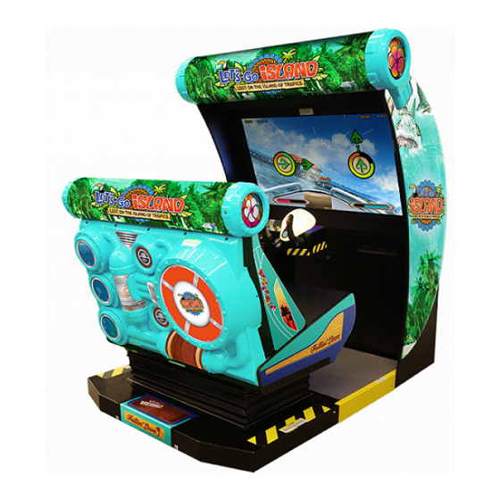
Page 23: Part Descriptions
PART DESCRIPTIONS FRONT CABINET BILLBOARD REAR DOOR REAR BILLBOARD SEAT FRONT DOOR AC UNIT REAR CABINET JOINT FLOOR MOTION STOP BUTTON 1P CONTROLLER 2P CONTROLLER 1P START BUTTON 2P START BUTTON COIN DOOR Items Width Depth Height FRONT CABINET 1,436mm (56.53 in) 880mm (34.64 in) 2000mm (78.74 in) (WITHOUT BILLBOARD) -
Page 24: Accessories
ACCESSORIES Confirm that the accessories listed in the table below are present when setting up the product. Accessories marked “Spare” in the note column are consumable items but included as spares. Parts not labeled with part numbers are yet to be assigned. Be sure to handle all parts with care, as some parts are not available for purchase separately. - Page 25 The DVD drive is sold separately but it is required in order to install the software for this product. If you do not have the drive when re-installing the product, consult the dealer which you purchased this product. Alternatively use the kit number below when ordering the drive from the SEGA SPARES DIVISION. Part name/Part no.
-
Page 26: Assembly And Installation
ASSEMBLY AND INSTALLATION • Perform assembly work by following the procedure herein stated. Failure to comply with the instructions can cause electric shock. • Perform assembling as per this manual. Since this is a complex machine, incorrect assembling can cause an electric shock, machine damage and/or improper functioning as per specified performance. • When assembling, be sure to use additional help from another person(s). Depending on the assembly work, there are some cases in which working by one person alone can cause personal injury or parts damage. - Page 27 • For the sake of safety and workability, use 3 core coaxial CE/UL approved cables for the power cables (provided). • When inserting or removing a connector, always hold it by its main part. If you hold it by anything else while doing so, the connections between wire and connector terminal fixtures could be damaged; and there could be a short circuit or fire. There could also be poor connectivity.
- Page 28 TOOLS NECESSARY FOR WORK Phillips Screwdriver (for M4) Torx T20 Security Driver Spanner / Adjustable spanner (24mm) Key Master Step or Stool Socket Wrench (13mm) Hex Key...
-
Page 29: Connecting Front And Rear Cabinets
CONNECTING FRONT AND REAR CABINETS Move the Display Cabinet to the installation location. Be carefully not to push on the screen or the plastic components. Place the product so that the back of the front cabinet is at least 0.15m (5.9 in) from the wall. Using a 24mm spanner, lower the Leg Adjusters until the casters have been raised from the ground approx 5mm. - Page 30 Fit the Board Harness (DV-0010UK) to the underside of the Joint Bridges and secure using the 4x M4 SKT CAP SCREWS. M4x16 SKT BH BLK (029-B00416-0B) Board Harness (DV-0010UK Route the harness from the Display cabinet through to the front of the Board as illustrated. Harness Carefully maneuver the Moving Seat cabinet into position so that the Joint Bridges located firmly into position.
- Page 31 Once the Motion Seat cabinet is secure to location, fit the 2x Joint Bridges (DV-0001UK) to the base of the Motion Seat cabinet. First remove the 8x fixings from the location points and slide the 2x Joint Bridges into position. Once in position re-fit the 8x fixings back into their location points. (Tighten all 16 fixings). M8x20 SKT CAP (4) M8x20 SKT CAP (4) Make all connections on the joining harness good. Harness from Display Cabinet Harness from Seat Cabinet...
-
Page 32: Installing The Floor
INSTALLING THE FLOOR Place the floor [DV-0002UK] into the space between the two cabinets, taking note of orientation. Secure into position using the JOINT SASH REAR [DV-0004UK] and secure using M4x14 SKT BH BLK [029-B00416-0B] (4), M4 WSHR BLK 16OD [068-441616-0B] (4) and M4 WSHR SRNG BLK [060-S00400-0B] (4) JOINT SASH REAR (DV-0004UK) JOINT FLOOR (DV-0002UK) - Page 33 Fit and secure the JOINT SASH FRONT (DV-0006UK) to the front edge of the floor, Secure into position using M4x14 SKT BH BLK [029-B00416-0B] [4] [068-441616-0B] [4] and (060-S00400-0B) [4] JOINT SASH FRONT (DV-0006UK) Secure using M4x14 SKT BH BLK [029-B00416-0B] [4] [068-441616-0B] [4] and (060-S00400-0B) [4]...
-
Page 34: Installing The Billboard
INSTALLING THE BILLBOARD Correctly position and secure the END CAP INNER (2) [DV-0512UK) to the ASSY BILLBOARD and secure using the M8x70 BLT PAS (4) and M8 WSHR 22OD FLT BLK (4). Do not tighten fixings at this point as it may prevent fixture to cabinet. END CAP INNER DV-0512UK M8x70 BLT PAS (4) M8 WSHR 22OD FLT BLK Using a minimum of 2 people and either a step or step ladder, carefully raise the Assy Billboard into position. - Page 35 Align the 3 holes each side of the Billboard and secure to cabinet using M8x50 BLT PAS (6) [030-00850] and M8 WSHR 20OD FLT BLK (6) [030-000850] - Tighten all 10 fixings. Fix into position using M8x50 BLT PAS (6) and M8 WSHR FLT BLK FIT END CAP HEADER (2) [LMI-0513UK] to both ends of the ASSY BILLBOARD and secure using M4x12 TMP PRF STN (8) [008-OS0412] and M4 WSHR 16OD FLT CRM (8) [068-441616-0C...
-
Page 36: Fixation To Site
FIXATION TO SITE • Make sure that all the adjusters contact the floor. Otherwise the cabinet could move, causing an accident. • Provide a ventilation space at least 15cm wide behind the cabinet. There are ventilation holes on the back of the cabinet. Do not block the ventilation holes. Doing so could trap heat inside resulting in fire. It could also result in equipment damage or cause parts to become exhausted prematurely. • Do not position the product on uneven surfaces or a surface which slopes. Positioning the cabinet on either an uneven or sloped surface may cause the cabinet to become unstable which may result in damage or injury. The product comes with castors attached to 8 locations. When the installation sire has been determined, have the ad- justers come in direct contact with the floor. Establish a gap of approximately 5mm between the floor and the castor and adjust the unit so that it will remain level. - Page 37 Move the product to location. When adjusting the front cabinet position, use the parts which are shaded to hold the cabinet. Be careful not to push/pull on the screen or any plastic parts which may break. Bring the adjusters into direct contact with the floor. Use a wrench to align the height of the adjusters until the cabinet is perfectly level. Not having the adjusters level will cause the cabinet to rock and move from position.. After setting. screw the nuts upwards to the base and tighten. This will prevent the adjusters from moving.
-
Page 38: Power Supply And Other Connections
POWER SUPPLY AND OTHER CONNECTIONS • Use the power supply equipped with an earth leakage breaker. Use of power supply without such a breaker could result in fire if there is a current leakage. • Have available a securely grounded indoor ground terminal. Without proper grounding, customers could be electrocuted and product operations might not always be stable. • Do not expose the power cord or ground wire. If these are exposed, customers could stumble over them, for instance, and easily damage them. Additionally, if these lines are damaged, there could be a risk of electrical shock or short circuit. -
Page 39: Turning On The Power
Fully insert the power cord connector on the side opposite the power plug into the AC unit IEC inlet. Insert the power cord plug into the outlet. The power code is laid out indoors. Protect the power cord by attaching wire cover to it. WIRE COVER TURNING ON THE POWER Set the main switch of the AC unit to ON and engage the power. When you turn on the power, the billboard LED’s will come on. After the start up screen is displayed on the LCD screen, the Advertise (Attract) Mode will start. - Page 40 COMPONENTS WHICH CHANGE STATE WHEN POWER IS APPLIED BILLBOARD ILLUMINATES GRAPHICS ON DISPLAY BILLBOARD ILLUMINATES AUDIO OUTPUT LAMPS ILLUMINATE SEAT MOVES LAMP ILLUMINATES...
-
Page 41: Confirmation Of Assembly
CONFIRMATION OF ASSEMBLY Use the TEST MODE to check whether or not the product has been correctly assembled and whether or not everything operates normally. • The seat moves during the initialization of the cabinet. Please wait and stand aside of the cabinet during this time. Do not touch the seat while it is initializing. Turn ON the power switch. The Billboard and Rear Moulding LED’s will illuminate along with the Plasma Disc. The Gameboard logo is displayed on screen The initialization screen appears on screen. -
Page 42: Applying Warning Labels (Epileptiform Seizures)
APPLYING WARNING LABELS (EPILEPTIFORM SEIZURES) • The operator MUST apply the Epileptiform Seizure Label to this product. Failing to apply this label may result in the player/observer suffering from a photosensitive seizure. Warning the potential player/ observer of this before the start of a game may prevent such accidents. • It is also important to apply the correct language label for each location. There are nine (9) different language labels - please apply the label which matches your location. Application of any warning labels must be placed in a location which is easy for the player/observer to read. Please follow the instructions below and apply the label in the location stated. -
Page 43: Precautions When Moving The Machine
PRECAUTIONS WHEN MOVING THE MACHINE • As used in these instructions, the term “moving” refers to moving of the product within the same building, store or facility. These instructions do not cover moving between different buildings, areas, stores or facilities, since diverse factors are involved, not only packaging but also loading onto transport vehicles, and securing the product in place during transport. To transport the product to a different building or store, contact the vendor where the product was purchased or the office indicated in these instructions. Or request that... - Page 44 • When inserting or removing a connector, always hold it by its main part. If you hold it by anything else while doing so, the connections between wire and connector terminal fixtures could be damaged; and there could be a short circuit or fire. There could also be poor connectivity. • Do not move unit with the adjusters in contact with the floor. Otherwise parts might be damaged or deformed and there might be accidents.
- Page 45 • Do not push plastic parts or any part associated with the moving mechanism. Do not lift or support the product by any plastic part. Parts can be damaged, and fragments can cause injury. • Do not push on or hold onto the LCD or controllers to move the unit. Doing so could break the parts and lead to people getting injured.. • Do not stack parts that have been separated or disassembled indiscriminately. The surface of the parts could be damaged or deformed. Significant deformations can result in improper operation and breakdowns. • Do not lean separated or disassembled parts against a wall or other surface indiscriminately. The parts could be deformed. Accidents could also occur should the parts fall over.
- Page 46 When moving across the floor, detach the rear cabinet, joint floor and front cabinet. If the height of the area in which the cabinet is to be moved changes it may be required to remove the Billboard. Refer to Chapter 6 and work in reverse order to reform disassembly BILLBOARD REAR CABINET...
- Page 47 PLAYING THE GAME PLAYING THE GAME 8-1 GAME OUTLINE “Let’s Go ISLAND!” is an action-adventure gun shooting game. Players sit on a moving seat and fire a machine gun at attacking giant enemies in a thrilling, adrenaline-charged gaming experience. Besides shooting giant creatures with a gun, the game includes a number of other mechanics to keep players’ interest, such as mashing buttons to escape from tight spots.
- Page 48 PLAYING THE GAME 8-2-2 BASIC CONTROLS TRIGGER 1P (left seat) target sight 2P (right seat) target sight Targets Sight Controller - Moving the controller will move the target sight on the screen. - Pulling the trigger fires a bullet. (Bullets are fired continuously as long as the trigger is held. You have unlimited ammunition.
- Page 49 PLAYING THE GAME HINTS FOR PLAYING THE GAME - Making a shot or performing an action that requires more skill than normal (a shot that makes a Shot Bonus appear or an S-Rank action) causes points to build in the Life Bottle Meter in the center of the screen. Life Bottle Meter - When the meter reaches a certain number of points, the player receives a set LIFE bonus..
-
Page 50: Explanation Of Test And Data Display
EXPLANATION OF TEST AND DATA DISPLAY Perform tests and data checks periodically by manipulating the TEST Button and SERVICE Button in the cabinet. Follow the instructions in this chapter to conduct checks when the game machine is first installed, when money is being collected, or when the game machine does not operate properly. -
Page 51: Switch Unit And Coin Meter
Press the TEST Button after powering on the unit to display the following SYSTEM TEST MODE. For further details, see the RINGWIDE service manaul. If you do not have a RINGWIDE service manual with this product, there is a copy available for download on the SEGA AMUSEMENTS website. (www.segaarcade.com) -
Page 52: Game Test Menu
9-3 GAME TEST MENU Press the TEST Button to enter TEST MODE and bring up the SYSTEM TEST MENU screen. Press the SERVICE Button to select “GAME TEST MODE”, then press the TEST Button to bring up the GAME TEST MENU screen. GAME TEST MENU BOOKKEEPING INPUT TEST... -
Page 53: Bookkeeping
9-4 BOOKKEEPING View game data. BOOKKEEPING COIN1 COIN2 TOTAL COINS COIN CREDITS SERVICE CREDITS TOTAL CREDITS PRESS TEST BUTTON TO NEXT BOOKKEEPING 1/3 screen ■Controls - Press the TEST Button to display the BOOKKEEPING 2/3 screen. ■Menu Items COIN 1/COIN 2 Displays the number of coins inserted into each coin insertion slot. - Page 54 BOOKKEEPING TOTAL TIME * D ** H ** M ** S PLAY TIME * D ** H ** M ** S PLAY TIME 1P * D ** H ** M ** S PLAY TIME 2P * D ** H ** M ** S NUMBER OF GAMES NUMBER OF GAME START 1P NUMBER OF GAME START 2P...
- Page 55 BOOKKEEPING TIME HISTOGRAM 00 – 01 min 14 – 15 min 01 – 02 min 15 – 16 min 02 – 03 min 16 – 17 min 03 – 04 min 17 – 18 min 04 – 05 min 18 – 19 min 05 –...
-
Page 56: Input Test
9-5 INPUT TEST View the status of input devices. Use this screen to perform periodic checks on input devices. INPUT TEST 1P CONT X 1P CONT Y 1P CONT TRIGGER_L 1P CONT TRIGGER_R 1P START BUTTON 2P CONT X 2P CONT Y 2P CONT TRIGGER_L 2P CONT TRIGGER_R 2P START BUTTON... - Page 57 2P CONT Y Normal if the displayed value changes accordingly when the 2P controller is moved up and down. Pointing the controller down decreases the value, while pointing it up increases the value. 2P CONT TRIGGER_L Normal if the display changes from “OFF” to “ON” when the left trigger on the 2P controller is pulled.
-
Page 58: Output Test
9-6 OUTPUT TEST View the status of output devices. Use this screen to perform periodic checks on output devices. OUTPUT TEST 1P CONT 1P START LAMP 2P CONT 2P START LAMP REAR LAMP > EXIT SELECT WITH SERVICE BUTTON AND PRESS TEST BUTTON OUTPUT TEST screen ■Controls - Press the SERVICE Button to select menu items. -
Page 59: Game Assignments
9-7 GAME ASSIGNMENTS Configure the game settings. GAME ASSIGNMENTS GAME DIFFICULTY NORMAL LIFE SETTING NORMAL ADVERTISE SOUND KIDS MODE DRESS CODE > EXIT SELECT WITH SERVICE BUTTON AND PRESS TEST BUTTON GAME ASSIGNMENTS screen ■Controls - Press the SERVICE Button to select menu items. - Press the TEST Button to change the value of the selected item. -
Page 60: Controller Calibration
9-8 CONTROLLER CALIBRATION Calibrate the 1P and 2P controllers. CONT CALIBRATION SETTING CALIBRATION START DEFAULT SETTING > EXIT SELECT WITH SERVICE BUTTON AND PRESS TEST BUTTON CONT CALIBRATION SETTING screen ■Controls - Press the SERVICE Button to select menu items. - Press the TEST Button to execute the selected item. - Page 61 CONT CALIBRATION SETTING 1P CONT X 1P CONT Y 2P CONT X 2P CONT Y 1P MIN_X MAX_X 1P MIN_Y MAX_Y 2P MIN_X MAX_X 2P MIN_Y MAX_Y PULL TRIGGER AND ROTATE CONTROLLER TO CALIBRATION PRESS TEST BUTTON TO SET AND EXIT CONT CALIBRATION SETTING screen 2 ■Controls - Pull the triggers on the 1P and 2P controllers and slowly move the controllers all the way up, down, left, and...
-
Page 62: Cabinet Setting
9-9 CABINET SETTING View and adjust cabinet settings. CABINET SETTING CABINET TYPE NONMOVE SEAT MOTION TEST GAME MOVEMENT MOVING ADVERTISE MOVE > EXIT SELECT WITH SERVICE BUTTON AND PRESS TEST BUTTON CABINET SETTING screen ■Controls - Press the SERVICE Button to select menu items. - Press the TEST Button to change the value of the selected item. -
Page 63: Seat Motion Test
9-9 SEAT MOTION TEST... -
Page 64: Backup Data Clear
9-10 BACKUP DATA CLEAR Clear backup data (the operational data contained in BOOKKEEPING). BACKUP DATA CLEAR YES(CLEAR) > NO(CANCEL) SELECT WITH SERVICE BUTTON AND PRESS TEST BUTTON BACKUP DATA CLEAR screen ■Controls - Press the SERVICE Button to select menu items. - Press the TEST Button to execute the selected item. -
Page 65: Controller Unit(S), Switches And Buttons
CONTROLLER UNIT(S), SWITCHES AND BUTTONS • When working with the product, be sure to turn the power off. Working with the power on may cause an electric shock or short circuit. • Be careful not to damage the wires. Damaged wires may cause an electric shock, short circuit or present a risk of fire. • Exercise due caution in performing soldering work. If soldering iron is handled carelessly, there could be fires or burns. • When fastening plastic parts, be careful not to tighten screws or nuts excessively. If these are tightened to excess, parts could be damaged, resulting in injuries from fragments, etc. • After the unit has been disassembled and reassembled again, check carefully that the unit has been reassembled correctly. • Be sure to inspect the outer covers on both gear and hand brake units. • Assemble so that there is no gap between the L and R covers. If there is a gap or rattling, the players could get fingers or hands caught, resulting in injury. • Once the product has been disassembled, use slack preventive agent (product No. : 090-0012-N). Coat screws with suitable amounts of this agent and then tighten them. If this agent is not used, the product might start rattling or come apart. • Use the slack preventive agent prescribed in these instructions. If any other agent is used, there could be chemical changes that inhibit the use of screws and part surfaces could be damaged. • Be careful not to damage or lose small parts or screws. • When a part has been replaced, be sure to always make adjustments and check conditions in Test Mode. -
Page 66: Adjusting/Replacing The Volume Pot
Be sure to perform volume's move value setting in the INPUT ASSIGNMENTS in the Game Test Mode after replacing or adjusting the Volume. 10-1 ADJUSTING/REPLACING THE VOLUME POT Turn off the power. Remove the 3 screws from the undersides of the Controller. REMOVE FIXINGS Carefully remove the Controller Cover to reveal the Volume Pots for adjusting. COVER... - Page 67 ADJUSTMENT PROCEDURE Apply this procedure to both Horizontal and Vertical Volume Pots. Loosen the 2 screws that secure the VR Bracket and move the VR Bracket to adjust the angle and condition of the gear alignment. LOOSEN FIXINGS H VOLUME BKT V VOLUME BKT Locate the central position of the pot by turning the pot in both clockwise ans counterclockwise positions.
- Page 68 REPLACEMENT PROCEDURE This procedure requires the following tools: Phillips screwdriver for the M4 screws, 1.5 mm hexagonal wrench, 11- 12 mm monkey wrench, nipper, cutter, wire stripper, soldering iron, industrial dryer and heat-shrinkable tube. Remove the connectors. Remove the 2 screws securing the VR Bracket and remove the entire Bracket and V.R. (See previous instruction) Loosen the 1 hexagon socket screws on the Gear Holder and remove the Gear Holder.
- Page 69 The wire connected to the volume pot will be reused. Use a tool such as a pair of snips or cutters to remove the old heatshrink tubes which cover the contacts. Use a soldering iron to melt the solder and seperated the wires from the old volume pot. Be very careful when using a soldering iron.
-
Page 70: Greasing
10-3 GREASING • Be sure to use the designated grease. Using undesignated grease can cause parts damage. • Do not apply grease to locations other than as specified. Doing so may create a risk of operational problems and deterioration of parts. • The designated periods for greasing serve only as a guide. Whenever there are squeaks or other anomalies, apply grease at designated locations. Use spray grease once every three months to grease up the gear mesh portion of the constituent parts. Use "Grease Mate" (part number 090-0066) for the spray grease. GREASING POINT GREASING POINT... -
Page 71: Start Button Assy
10-4 START BUTTON ASSY ● When working with the product, be sure to turn the power off. Working with the power on may cause an electric shock or short circuit. ● Be careful not to damage the wires. Damaged wires may cause an electric shock, short circuit or present a risk of fire. If the start switch input does not function correctly on the INPUT TEST screen, the switch may need to be replaced. To carry out this maintenance, you must first remove the start button unit. For this task, you will need a tamper proof wrench (for M4 screws), Start Button Removal Turn the power OFF Unlock and open the coin door in order to gain access to the rear of the START BUTTON ASSY. -
Page 72: Graphics Display
GRAPHICS DISPLAY 11-1 SAFETY PRECAUTIONS WHEN HANDLING THE MONITOR Responding to breakdown or abnormality ● If smoke or a strange odor appears, immediately unplug the power cable from the power source. Continuing to use the product may cause a fire or an electric shock. Ensure that smoke is no longer emitted, and contact the point of purchase. ● If nothing displays on the screen, immediately unplug the power cable from the power source. Continuing to use the product may cause a fire or an electric shock. Contact the point of purchase and request an inspection. ● If water or a foreign object enters the monitor’s interior, immediately unplug the power cable from the power source. Continuing to use the product may cause a fire or an electric shock. Contact the point of purchase and request an inspection. ● If the monitor is dropped or the cabinet is damaged, immediately unplug the power cable from the power source. Continuing to use the product may cause a fire or an electric shock. Contact the point of purchase and request an inspection. During operation ● Do not repair, reconstruct, or disassemble the monitor. The monitors interior contains high voltage parts. A fire or an electric shock could result. For inspections, adjustments, and repair of the monitors interior, request work from the point of purchase. - Page 73 11-2 CLEANING THE SCREEN SURFACE ● Use a soft, dry cloth (flannel-type) to wipe away dirt. Do not use materials such a s coarse mesh gauze. ● Alcohol (ethanol) is the recommended solvent for removing dirt. When using a c leaning agent, follow the precautions below. - Dilute neutral cleaning agents for home use with water. Soak a soft cloth in the s olution, and wring it thoroughly before wiping the screen. - Do not use abrasive cleaning agents or powders, or cleaning agents c ontaining bleach. - Do not use alkaline cleaning agents such as glass cleaners, or solvents such as t hinners. ● Do not scrub or scratch the screen surface with abrasive materials such as b rushes or scrub brushes. CLEAN THE SCREEN DAILY.
- Page 74 11-3 ADJUSTMENT METHOD All adjustment values are set accurately at the time of shipping from the factory. Do not readjust these values needlessly or apply adjustments not specified in this manual. The display may not appear properly if the values are incorrect.
- Page 75 11-3 ADJUSTMENT METHOD Button Names and Functions 11-3 Fig. 02 MENU: Turn the Picture Menu display ON and OFF. SELECT: Gains entry to the Item selected in the menu. (Highlights in Yellow when selected) Exits the Item adustment. Any changes made during this operation are actioned.
- Page 76 11-3 ADJUSTMENT METHOD On-Screen Display (OSD) Press the MENU Button while the OSD is not displayed to bring up the Picture Menu. On the Picture Menu, it is possible to perform various screen adjustments. 11-3 Fig. 03 Use the UP and DOWN Buttons to move the ‘Black Bar’to the item you want to adjust. After selecting the desired item, pressing the SELECT Button will extend the MENU Screen and allow adjustments to be changed.
- Page 77 11-3 ADJUSTMENT METHOD On-Screen Display (OSD) <continued> 11-3 Fig. 06 Available Settings (Selects Operation Mode)) Selection availble - 6500K - 9300K - USER BRIGHTNESS (Adjust Brightness) Adjust screen Brightness. - Values: 0 - 100 (0” being the darkest setting, and “100” being the brightest) CONTRAST (Adjust Contrast) Adjust Contrast level.
-
Page 78: Coin Handling
COIN HANDLING Handling the Coin Jam If the coin is not rejected when the REJECT button is pressed, open the coin chute door and open the selector gate. After removing the jammed coin, put a normal coin in and check to see that the selector correctly functions. 12-1 CLEANING THE COIN SELECTOR ● Remove and clean smears by using a soft cloth dipped in water or diluted chemical... - Page 79 CLEANING THE COIN SELECTOR (MECHANICAL). Remove and clean smears by using a soft cloth dipped in water or diluted chemical detergent and then squeezed dry. Remove the CRADLE.. When removing the retaining ring (E ring) be very careful so as not to bend the rotary shaft.
- Page 80 CLEANING THE COIN SELECTOR (SR3) <continued> Remove and clean smears by using a damp soft cloth dipped in water. DO NOT use any diluted chemical detergent or cleansing agent as this will impair the workings of the component. GATE Open the reject gate to gain access to the rundown path.
-
Page 81: Fault Finding
12-2 FAULT FINDING Fault Finding The following information is presented for customers’ guidance in rectifying a fault but does not cover all possible causes. All acceptors with electronic faults should be returned to an approved service centre for repair. SYMPTOM INVESTIGATE POSSIBLE CAUSE Poor Contact... -
Page 82: Adjusting The Price Of Play (Excel)
12-3 ADJUSTING THE PRICE OF PLAY (EXCEL) ● The price of play is determined by the configuration of switches located on either an EXCEL board or VTS board. The type of board used is determined by product location. Switch settings for both types of board remain the same. This product comes equipped with a Money Controls SR3 Coin Acceptor. To adjust the price of play ALL credit setting are adjusted via the EXCEL CREDIT BOARD. -
Page 83: Adjusting The Price Of Play (Vts)
12-4 ADJUSTING THE PRICE OF PLAY (VTS) This product comes equipped with a Money Controls SR3 Coin Acceptor. To adjust the price of play ALL credit setting are adjusted via the EXCEL CREDIT BOARD. IMPORTANT! The CREDIT SETTINGS within the SYSTEM TEST MODE must be set to 1 coin 1 credit to allow the CREDIT BOARD to function correctly. - Page 84 REGIONAL AND ACCEPTOR SETTINGS (SW3)
- Page 85 STERLING PRICE OF PLAY SETTINGS (SW1)
- Page 86 EURO PRICE OF PLAY SETTINGS (SW1)
-
Page 87: Seat Mechanism
SEAT MECHANISM • This work should be performed by site maintenance personnel or other skilled professionals. Work performed by non-technical personnel can cause a severe accident such as electric shock. • When working with the product, be sure to turn the power OFF. Working with the power on may cause an electric shock or short circuit. • Exercise due caution in performing soldering procedures. If a soldering iron is handled carelessly it could cause a burn or start a fire. • Proceed very carefully when heating thermal contraction tubes (heatshrink). Careless heating of such tubes may can cause burns or fire. • Be careful not to damage wires. Damaging wires may cause electric shock, short circuit or present a risk of fire. • Do not touch undesignated places. Handling or touching such places may cause an electric shock, short circuit or crush hazard. -
Page 88: Pitch Volume
13-1 PITCH VOLUME 13-1-1 PITCH VOLUME ADJUSTMENT Turn OFF the power switch. Note: Turn off the power when the cabinet is in Advertise Mode and the seat is not moving. Using an Allen wrench, remove the 4 inner hex socket screws positioned along the top rail of the seat back. Once removed carefully lift the seat back in an upwards movement to unlatch it for the base. - Page 89 Locate the Pitch Volume Bracket and loosen the 2 screws to adjust the gear mesh angle and seating. Ensure that the D cut surface of the volume control axis is as shown in the figure when the seat is in its horizontal position.
- Page 90 VALUE DECREASES VALUE INCREASES 13-1-2 PITCH VOLUME REPLACEMENT Turn off the power when the seat is in Advertise Mode and the seat in NOT moving. Refer to Steps 2 to 4 in the previous section to remove the Seat back and base. Undo the cord clamp and disconnect the connector.
- Page 91 Remove the setscrews and remove the gear from the volume shaft. Remove the nut holding the pitch volume bracket in place and take the volume off the pitch volume bracket. The wires connect to the volume will be reused. Use a tool such as a pair of snips or cutters to remove the old heatshrink tubes from the areas were the wires are connected.
- Page 92 13-1-3 PITCH VOLUME GREASING • Be sure to use the designated grease. Using an undesignated grease can cause parts damage. • Do not apply grease to locations other that those specified. Doing so may create a risk of operational problems and deterioration of parts. • The designated periods for greasing serve only as a guide. Whenever there are squeaks or other anomalies, apply grease at designated locations. Grease the parts listed below once every three months. Use GREASE MATE (PART No. 090-0066) spray grease. Refer to steps 1 to 4 of 13-1-1 PITCH VOLUME ADJUSTMENT and remove the seat and seat back. Grease the gear interface as shown in the figure.
-
Page 93: Roll Volume
13-2 ROLL VOLUME 13-2-1 ROLL VOLUME ADJUSTMENT Turn OFF the power switch. Note: Turn off the power when the cabinet is in Advertise Mode and the seat is not moving. Remove the 4 screws and take off the bellows upper base hatch. SCREW (4) Below base hatch Loosen the 2 screws and move the volume bracket to adjust the gear mesh angle and seating position. - Page 95 13-2-2 ROLL VOLUME REPLACEMENT Turn OFF the power switch. Note: Turn off the power when the cabinet is in Advertise Mode and the seat is not moving. Refer to step 2 of 13-2-1 ROLL VOLUME ADJUSTMENT and remove the upper bellow base hatch. Undo the cord clamp and disconnect the connector.
- Page 96 Remove the nut holding the roll volume bracket in place and take the volume off the roll volume bracket. The wires connect to the volume will be reused. Use a tool such as a pair of snips or cutters to remove the old heatshrink tubes from the areas were the wires are connected.
- Page 97 13-2-3 ROLL VOLUME GREASING • Be sure to use the designated grease. Using an undesignated grease can cause parts damage. • Do not apply grease to locations other that those specified. Doing so may create a risk of operational problems and deterioration of parts. • The designated periods for greasing serve only as a guide. Whenever there are squeaks or other anomalies, apply grease at designated locations. Grease the parts listed below once every three months. Use GREASE MATE (PART No. 090-0066) spray grease. Refer to steps 1 to 4 of 13-2-1 ROLL VOLUME ADJUSTMENT and remove the upper bellows hatch. Grease the gear interface as shown in the figure.
-
Page 98: Periodic Inspection
PERIODIC INSPECTION The items listed below require periodic check and maintenance to retain the performance of this machine and to ensure safe business operation. When handling the controller, the player will be in direct contact with it. In order to always allow the player to enjoy the game, be sure to clean it regularly. - Page 99 Cleaning the Cabinet Surfaces When the cabinet surfaces are badly soiled, remove stains with a soft cloth dipped in water or diluted with a chemical detergent and squeezed dry. To avoid damaging surface finish, do not use such solvents as thinner, benzine, etc.
- Page 100 PERIODIC INSPECTION TABLE PERIOD ITEMS DESCRIPTION As appropriate CABINET SURFACE Cleaning LAMPS Inspection Daily CABINET Confirm adjusters contact floor SAFETY DEVICES Confirm bellows Check rubber on foot guard Check perimeter sensors ON/OFF Weekly Screen Cleaning Check monitor adjustment MOTION STOP Check switch operation Monthly START Check switches and lamps...
-
Page 101: Troubleshooting
TROUBLESHOOTING 11-1 TROUBLESHOOTING (WHEN NO ERROR MESSAGE IS SHOWN) • In order to prevent electric shock and short circuit, be sure to turn power off before performing work. • Be careful so as not to damage wirings. Damaged wiring can cause electric shock or short circuit. - Page 103 PROBLEM CAUSE COUNTERMEASURE With main switch ON there Power is not supplied Insert power lead all the way into is no activation outlet Supply voltage is not correct Make sure that supply voltage is correct Circuit protector activated Reset circuit protector/replace fuse There is sound and lighting Video signal connector or...
-
Page 104: Game Board (Ringwide)
GAME BOARD (RINGWIDE) ● When working with the product, be sure to turn the power off. Working with the power on may cause an electric shock or short circuit. ● Be careful not to damage the wires. Damaged wires may cause an electric shock, short circuit or present a risk of fire. ● Do not use this product with connectors other than those that were connected and used with the game board at the time of shipping. Do not carelessly connect wires to connectors that were not used at the time of shipping, as this may cause overheating, smoke or fire damage. In this product, setting changes are made during the test mode. The game board need not be operated. Use the game board, etc. as is with the same setting made at the time of shipment so as not to cause electric shock and malfunctioning. Static electricity from your body may damage some electronics devices on the IC board. Before handling the IC board, touch a grounded metallic surface so that the static electricity can be discharged. - Page 105 16-1 HANDLING PRECAUTIONS ● To prevent electric shock or IC Board malfunctioning, be sure to turn off the power for the cabinet when installing or removing the IC Board. ● Extraneous matter such as dust on the IC Board can cause the IC Board to generate heat and result in a fire due to short circuit, etc. Ensure the IC Board surfaces are always kept clean. ● Keep the IC board well cooled. RINGWIDE is provided with ventilating fans. Do not block the air outlets of these fans. Also do not place anything closely to RINGWIDE. Failure to observe these instructions may cause an overheating and fire. ● Always follow the usage conditions from SEGA as well as the usage conditions for the cabinet you are using for RINGWIDE. Failure to do so may cause an overheating and fire. ● Be sure to connect the IC Board and connectors completely. Insufficient insertion can damage IC Board, etc. ● For the IC Board circuit inspection, only the use of Logic Tester is permitted. The use of ordinary testers is not permitted as these can damage the IC Board. ● Do not subject the IC Board to static electricity when installing the IC Board in the cabinet or when connecting wire harness connectors to the IC Board. ● When soldering buttons, etc. to the wire harnesses, be sure to remove the wire harnesses from the IC Board so as not to subject the IC Board to heat. ● Using RINGWIDE without the Shield Case can cause electric wave trouble. Be sure to use RINGWIDE together with the accessory Shield Case. ● Some parts are the ones designed and manufactured not specifically for this product. The manufacturers may discontinue, or change the specifications of, such general-purpose parts. If this is the case, SEGA cannot repair or replace a failed product whether or not a warranty period has expired.
- Page 106 16-2 PARTS DETAILS Shield case Exhaust vent (Do not block or cover.) Intake vent (Do not block or cover.) Board number Board serial number...
- Page 107 CONNECTORS, SWITCHES AND LED ● When connecting the connector, check the orientation and type carefully and connect securely. The connector must be connected in the proper direction and type. If it is connected in the wrong direction or indiscriminately at an incline, or connected wrong connector, so that a load is applied, the connector or its terminal pins could break, causing a short circuit or fire. ● Do not connect components to JVS I/O that are not designated by SEGA. Connecting unspecified components could cause an accident such as an electric shock or fire. Power input port External power supply port Test/Service button external input port DIP SW (Dip switches) Service button (SW2) LED1, LED2 (From right to left: 1, 2)
- Page 108 1 Power Input Port Terminal Signal Terminal Signal Name Name +12V DC IN +12V DC IN +12V DC IN +12V DC IN NOTE: Before connecting, be sure to check the type of connector. 2 External Power Supply Port Terminal Signal Terminal Signal Maximum Output Current Name Name +12V DC +12V DC 2.3A +12V DC...
- Page 109 4 DIP SW No. 1, No. 2 and No.3: Use differs depending on game software. Set according to the Service Manual provided with the game software itself. No. 4: Changes the facing of the monitor. Use differs depending on game software. Set according to the Service Manual provided with the game software itself.
- Page 110 16-3 RINGWIDE COMPONENTS ■ ACCESSORIES Parts not labeled with part numbers are as yet unregistered or cannot be registered. Be sure to handle all parts with care, as some parts are not available for purchase separately. DESCRIPTION/PART NO. FIGURES/NOTES TAPPING SCREW 011-P00412 Used for installing the RINGWIDE.
- Page 111 16-4 ERROR CODE DISPLAY ● If an error code is displayed get on-site maintenance personnel or other qualified professional to look at it. An unqualified person attempting to resolve an error code problem may lead to electric shock, short circuit and risk of fire. If no on-site maintenance personnel or qualified professional is available immediately turn off the power and contact the customer services in this manual or your supplier. ● If a problem not described in this manual occurs, or the resolution to a problem described in this manual is not effective, do not make further attempts to resolve the problem yourself. Immediately turn off the power and contact the office listed in this manual or your supplier. Any unguided attempts to solve such problems may lead to a serious accident. If an error number or message not listed below appears, cease using the product immediately and contact the office listed in this manual or the point of purchase for this product. RINGWIDE is equipped to display various errors on-screen to help solve any problems. If an error is displayed the game cannot be used.
- Page 112 DISPLAY Error 0008 Keychip Access Failed CAUSE The key chip could not be accessed. COUNTERMEASURES Reinsert the key chip and restart RINGWIDE. If that doesn’t fix the problem, contact the office listed in this manual or the point of purchase for this product. DISPLAY Error 0010 Unexpected Game Program Failure...
- Page 113 DISPLAY Error 0042 Game Program Not Found on Install Media CAUSE Some part of the game program is missing. COUNTERMEASURES Check how the game was installed. If that doesn’t fix the problem, contact the office listed in this manual or the point of purchase for this product.
- Page 114 DISPLAY Error 0082 Game Program Access Failed CAUSE The storage device cannot be recognized. COUNTERMEASURES Reinstall the game program. If that doesn’t fix the problem, contact the office listed in this manual or the point of purchase for this product. DISPLAY Error 0083 Storage Device Not Acceptable...
- Page 115 DISPLAY Error 0531 (No message) CAUSE The connected graphics device cannot be recognized. COUNTERMEASURES Turn the power off and then restart the RINGWIDE. If that doesn’t fix the problem, contact the office listed in this manual or the point of purchase for this product.
- Page 116 DISPLAY Error 0906 Sound Function Not found CAUSE The RINGWIDE sound function cannot be recognized. COUNTERMEASURES Contact the office listed in this manual or the point of purchase for this product. DISPLAY Error 0907 Not Enough System Memory CAUSE RINGWIDE does not have enough memory. COUNTERMEASURES Contact the office listed in this manual or the point of purchase for this product.
- Page 117 GAME ERROR CODES DISPLAY Error 1001 There is an error in the COIN ASSIGNMENTS SETTINGS. CAUSE COIN ASSIGNMENTS SETTINGS are incorrect. COUNTERMEASURES Make sure “SYSTEM TEST MODE” > “COIN ASSIGNMENTS” > “COIN CHUTE TYPE” and “SERVICE TYPE” are both set to “COMMON.” DISPLAY Error 6001 Unable to recognize SEAT MOTOR DRIVE BD.(PITCH)
- Page 118 DISPLAY Error 6009 The SEAT VOLUME is abnormal.(PITCH) CAUSE There is something wrong with the SEAT VOLUME (PITCH). COUNTERMEASURES Refer to 14-1-1 “PITCH VOLUME ADJUSTMENT” and adjust the volume. If the error per- sists, it is likely a faulty volume. Replace the volume. DISPLAY Error 6011 Unable to recognize SEAT MOTOR DRIVE BD.(ROLL)
- Page 119 Manual Recovery Use the following procedure to return the RINGWIDE system software to a previous state. Press the TEST and SERVICE Buttons simultaneously with the RINGWIDE power off. Hold the buttons down and turn on the power. After RINGWIDE starts up and the following message is displayed, release the buttons. The system software will recover automatically.
- Page 120 16-5 REPLACING THE BUTTON BATTERY ● Make sure you do not damage the printed board and wires. Such damage can lead to electric shock, short circuit and fire hazard. ● To prevent overheating, explosion, or fire: - Do not recharge, disassemble, heat, incinerate, or short the battery. - Do not allow the battery to come into direct contact with metallic objects or other batteries. - To preserve the battery, wrap it in tape or other insulating material. ● Follow local regulations when disposing of the battery. Improper disposal can damage the environment. ● Even the site maintenance personnel or other qualified professionals must not perform replacement operations for parts not described in this manual. In the event that such work is required either contact the office listed in this manual or first confirm the procedure with the place or office of purchase. Failure to do so may lead to electric shock or short circuit. ● Do not turn on the power with current carrying parts exposed. Doing so could result in electric shock or short circuit. To avoid risk of malfunction and damage: - Make sure the positive and negative ends are aligned correctly. - Use only batteries approved for use with this unit. ● The batteries in RINGWIDE can be used for approximately 4 years of standard usage. If the battery appears to require replacement sooner than 4 years it is more likely that an error has occurred with some other part of the board. Rather than exchanging the battery requesting repair of the board itself may be more appropriate. ● Static electricity from your body may damage some electronics devices on the IC board. Before handling the IC board, touch a grounded metallic surface so that the static electricity can be discharged.
- Page 121 The button battery that require replacement can be found on the main board, inside the RINGWIDE shield case. Remove the unit on which RINGWIDE is placed from the game cabinet. RINGWIDE must be removed still attached to the base (wooden shelf, etc.). Remove 2 screws for the RINGWIDE lid.
- Page 122 16-6 CLEANING RINGWIDE ● Clean RINGWIDE once a year or whenever either “Error 0090” or “Error 0091” occurs. Dust accumulating in game boards may not function properly. ● Set each cabinet to correct settings after cleaning the product. Be sure to set RINGWIDE to correct settings when returning. If the proper settings are not used, the units may not function properly. Once a year remove RINGWIDE from the cabinet and use a vacuum cleaner to clean around the RINGWIDE’s air vents and installation area. Refer to the manual included with the game machine, and remove RINGWIDE from the cabinet. Clean around the intake/exhaust vents of RINGWIDE with a vacuum cleaner.
- Page 123 Clean around installment parts of RINGWIDE in the cabinet with a vacuum cleaner. Be sure not to damage wirings and boards. Electronic devices on boards may damage by static electricity, and be sure not to vacuum electronic devices by a vacuum cleaner. Set each RINGWIDE you removed by the reverse method.
- Page 124 16-7 GAME BOARD (RINGWIDE) - LOCATION ● When returning the game board after making repairs or replacements, make sure that there are no errors in the connection of connectors. Erroneous connections can lead to electrical shock, short circuits or fires. ● When connecting a connector, check the direction carefully. Connectors must be connected in only one direction. If indiscriminate loads are applied in making connections, the connector or its terminal fixtures could be damaged, resulting in electrical shock, short circuits or fires. The machine is fitted with a Ringwide Game Board and several other Ancilliary Boards which are mainly housed inside the Display Cabinet.
- Page 125 FIXING POINTS (4) TAKE WEIGHT WHILST REMOVING FIXINGS Do not open the Game Board without the express permission of SEGA. If for any reason entry has been gained into the Game Board without the permission of SEGA, then all warranty rights become void. When returning the Game Board to SEGA for service, then please make sure that...
-
Page 126: Design-Related Parts
DESIGN-RELATED PARTS For the warning display stickers, refer to Section 1. HEADER INSERT EDCAP (LIM-0522UK) (LIM-0513UK) STKR ENDCAP (LIM-0514UK) STKR FRONT CABI R (LIM-1051UK) STKR REAR SIDE UPPER R (LIM-3513UK) STKR REAR SIDE R (LIM-3511UK) STKR END CAP (LIM-3014K) STKR FRONT CABI L (LIM-1050UK) STICKER REAR UPPER L (LIM-3512UK) - Page 127 TUBE INSERT (LIM-3022UK) STKR MID UPPER (LIM-3714UK) STKR LIT L OUTER LIFE BELT STKR (LIM-3719UK) (LIM-3720UK) STKR MID LOWER (LIM-3715UK) STKR TUBE HOR (LIM-3717UK) STKR TUBE VERT (LIM-3716UK) ENDCAP (LIM-3013UK) STKR FACE TOP STKR WARN SEAT MOVE (LIM-3722UK) (DV-3724UK) STKR MANIFOLD (LIM-3723UK)
-
Page 129: Parts List
PARTS LIST ASSY TOP LET'S GO ISLAND STRUCTURE TOP ASSY LET'S GO ISLANDBOM STRUCTURE LIM-0000UK TOP ASSY LET'S GO ISLAND DE **** ***** LIM-1000UK DV-1020UK ASSY MAIN CABI ASSY SPEAKER DV-1080UK ASSY AC UNIT DV-1100UK ASSY 52 LCD DISPLAY DV-1340UK... - Page 130 1 ASSY TOP LET'S GO ISLAND (LIM-0000UK) (D-1/2) ITEM NO PART NO DESCRIPTION LIM-1000UK ASSY MAIN CABI LIM-3000UK ASSY REAR CABINET DV-3860UK ASSY COIN CRADLE 421-7988-91UK STICKER SERIAL NUMBER UK 421-7020UK STICKER CAUTION FORK LB1102 STICKER DANGEROUS VOLTAGE LB1046 LABEL TESTED FOR ELEC. SAFETY...
- Page 131 1 ASSY TOP LET'S GO ISLAND (LIM-0000UK) (D-2/2)
- Page 132 2 ASSY BILLBOARD (LIM-0500UK) (D-1/2) ITEM PART NO DESCRIPTION ***1 DV-0501UK BILLBOARD ENCLOSURE DV ***2 DV-0511UK TUBE BILLBOARD ***4 DV-0515UK SASH TUBE FRONT ***5 DV-0516UK SASH TUBE REAR ***6 LIM-0522UK TUBE HEADER INNER INSERT ***7 SSR-1225UK LIGHT COVER CHEEK SHORT ***106 390-2012-RGB LED STRIP RGB...
- Page 133 2 ASSYBILLBOARD (LIM-0500UK) (D-2/2)
- Page 134 3 ASSY MAIN CABINET (LIM-1000UK) (D-1/2) ITEM NO PART NO DESCRIPTION DV-1002UK ASSY FRONT CABINET DV-1080UK ASSY AC UNIT DV-1100UK ASSY LCD DISPLAY DV-1020UK ASSY SPEAKER **10 DV-1340UK ASSY 100V FAN **11 RD-1340UK ASSY 120V FAN **12 DV-1002-DUK PANEL 52 INCH LCD MOUNTING **13 DV-1006UK BRKT FRONT BRIDGE JOINT...
- Page 135 3 ASSY MAIN CABINET (LIM-1000UK) (D-2/2) **306 DV-60008UK WH I/O & AUDIO **307 DV-60010UK WH DC SERIAL OUT **308 DV-60011UK WH SPKR MAIN CAB **309 DV-60039UK WH BLOWER EXTN **310 600-7158-0150UK WH 3.5 JACK TO RCA **311 600-7009-3000 ASSY RGB CA D-SUB 15 **312 600-7141-100UK CABLE JVS TYPE A-B 100CM...
- Page 136 4 ASSY FRONT CABI (DV-1002UK) (D-1/1) 201 202 ITEM NO PART NO DESCRIPTION ***1 DV-1002-AUK CABI BLANK ***2 DV-1002-BUK DOOR FRONT ***3 DV-1002-CUK DOOR BACK ***4 ADH-F0038UK ADJUSTER PLATE ***101 601-5699UK-01 LEG ADJUSTER M16X100 1L/NUT ***102 CASTOR ***104 LOCK RADIAL PIN ***105 117-0062 PLATE LOCK RETAINER SPIKE WASH...
- Page 137 5 ASSY SPEAKER (BE-1020UK) (D-1/1) 201 202 203 ITEM NO PART NO ***1 DV-1027UK BRKT SPEAKER MOUNT ***101 130-5156-02-91 SPEAKER BOX 8OHM 20W VA1 YL ***201 030-000512 M5X12 BLT PAS ***202 060-S00500 M5 WSHR SPR PAS ***203 068-551616 M5 WSHR 16OD FLT PAS...
- Page 138 6 ASSY AC UNIT (DV-1080UK) (D-1/1) ITEM NO PART NO DESCRIPTION ***1 DV-1081UK PLATE AC ***2 ST-0403UK PLATE AC CAP ***3 LB1096 STICKER PROTECTIVE EARTH ***101 EP1302 EUROSOCKET FUSED 10A 250VAC ***102 514-5078-5000 FUSE 5X20 CERAMIC SB 5000mA ***103 SW1109 SWITCH ROCKER 250V AC ***104 EP1419...
- Page 139 7 ASSY LCD DISPLAY 52"/55" (DV-1100UK/DV-1200UK) (D-1/1) ITEM NO PART NO DESCRIPTION ***3 DV-1106UK BRKT LCD MOUNT ***7 LGI-1110UK PANEL PRISMA BD MOUNT ***101 200-6052-SMSNG DISPLAY 52" LCD SAM LT1520HB02 ***101 200-6055-SMSNG DISPLAY 55" LCD SAM LT1520HB02 (USA/ASIA) ***102 400-356-024-01 PSU 52 LCD PVP-3680 ***103 280-A01264-WX...
- Page 140 8 ASSY CONTROLLER (DV-2000UK) (D-1/1) 202 203 ITEM NO PART NO DESCRIPTION ***1 DV-2001-01UK CONT CHASSIS W/BLK HANDLE ***2 DV-2002UK BRKT LIGHT MTG INTERNAL ***3 DV-2003UK STKR GUN BACK ***4 DV-2004UK CONT COVER ***101 601-0460-0W CABLE TIE WHT 100MM ***102 390-2012-RGB LED FLEX STRIP RGB 0.05...
- Page 141 9 ASSY FAN (DV-1340UK) (D-1/1) ITEM NO PART NO DESCRIPTION ***1 GST-1008UK BRKT FAN ***101 260-0011-02 FAN AC100V 50-60HZ (SP100A-1123 X 5T) ***102 FN1012 FAN GUARD METAL 120MM (FG-12) ***103 OS1195 RIVET SNAP SR-4080B ***201 000-P00312-W M3X12 MSCR PAN W/FS PAS ***301 ST-60026UK WH 240V FAN...
- Page 142 10 ASSY REAR CABINET (LIM-3000UK) (D-1/3) ITEM NO PART NO DESCRIPTION DV-3100UK ASSY MOVING MECHA DV-3500UK ASSY BENCH WOOD DV-3600UK ASSY SEAT BTM DV-3650UK ASSY SEAT BACK DV-3700UK ASSY REAR VAC DV-3001UK BELLOW UPPER BASE FRONT DV-3002UK BELLOW UPPER BASE REAR DV-3003UK BELLOW UPPER BASE HATCH DV-3005UK...
- Page 143 10 ASSY REAR CABINET (LIM-3000UK) (D-2/3) **216 060-S00400-0B M4 WSHR SPR BLK **217 068-441616-0B M4 WSHR 16OD FLT BLK **218 030-000830 M8X30 BLT PAS **219 030-000850 M8X50 BLT PAS **220 000-F00412 M4X12 MSCR CSK PAS **221 008-OS0412 M4X12 TMP PRF STN **222 068-441616-0C M4 WSHR 16OD FLT CRM...
- Page 144 10 ASSY REAR CABINET (LIM-3000UK) (D-3/3)
- Page 145 11 ASSY MOVING MECHA (DV-3100UK) (D-1/2) ITEM NO PART NO DESCRIPTION ***1 DV-3101UK REAR BASE ***2 LGI-3200 ASSY MOVING POST ***3 LGI-3280 ASSY ROLL SHAFT ***4 LGI-3300 ASSY PITCH BASE ***5 LGI-3400 ASSY ROLL VOLUME ***6 LGI-3420 ASSY PITCH VOLUME ***12 LGI-3004 BELLOWS...
- Page 146 11 ASSY MOVING MECHA (DV-3100UK) (D-2/2) 211 211 210 210 212 213 202 203 204...
- Page 147 12 ASSY MOVING POST (LGI-3200) (D-1/1)
- Page 148 13 ASSY ROLL MOTOR UNIT (LGI-3220) (D-1/2)
- Page 149 13 ASSY ROLL MOTOR UNIT (LGI-3220) (D-2/2)
- Page 150 14 ASSY ROLL ROD END (D-1/1)
- Page 151 15 ROLL FAN UNIT (LGI-3270) (D-1/1)
- Page 152 16 ASSY ROLL SHAFT (LGI-3280) (D-1/1)
- Page 153 17 ASSY PITCH BASE (LGI-3300) (D-1/1)
- Page 154 18 PITCH FAN UNIT (LGI-3370) (D-1/1)
- Page 155 19 ASSY PITCH SHAFT L (LGI-3380) (D-1/1)
- Page 156 20 ASSY PITCH SHAFT R (LGI-3390) (D-1/1)
- Page 157 21 PITCH MOTOR UNIT (LGI-3320) (D-1/2)
- Page 158 21 PITCH MOTOR UNIT (LGI-3320) (D-2/2)
- Page 159 22 ASSY PITCH ROD END (LGI-3350) (D-1/1)
- Page 160 23 ASSY ROLL VOLUME (LGI-3400) (D-1/1)
- Page 161 24 ASSY PITCH VOLUME (LGI-3420) (D-1/1)
- Page 162 25 ASSY REAR BASE (DV-3101UK) (D-1/1) ITEM NO PART NO DESCRIPTION ****1 DV-3102UK REAR BASE BLANK ****101 601-5699UK-01 LEG ADJ M16X100 1L/NUT ****102 MA1007 CASTOR SWIVEL 63mm NYLON ****201 ****202 030-000816 M8X16 BLT PAS ****203 060-S00800 M8 WSHR SPR PAS ****204 060-F00800 M8 WSHR FORM A FLT PAS...
- Page 163 26 ASSY BENCH WOOD (LIM-3500UK) (D-1/1) 206 207 208 ITEM NO PART NO DESCRIPTION ***1 DV-3502UK BENCH WOOD ***4 DV-3520UK BELLOW UPPER BASE L ***5 DV-3521UK BELLOW UPPER BASE R ***6 DV-3522UK REAR CRG PLATE ***9 LIM-3510UK STICKER REAR SIDE L ***10 LIM-3511UK STICKER REAR SIDE R...
- Page 164 27 ASSY BENCH WOOD SUB (DV-3502UK) (D-1/1) ITEM NO PART NO DESCRIPTION ****1 DV-3502-AUK BENCH WOOD BLANK ****2 DV-3503UK REAR NUT PLATE A ****3 DV-3504UK REAR NUT PLATE B ****4 DV-3505UK SEAT RACK BRKT REAR L ****5 DV-3506UK SEAT RACK BRKT REAR R ****6 DV-3507UK SEAT RACK BRKT FRONT L...
- Page 165 28 ASSY SEAT BOTTOM (DV-3600UK) (D-1/1) ITEM NO PART NO DESCRIPTION ***1 DV-3601-AUK SEAT WOOD ***2 DV-3602UK SEAT HOOK BRKT ***3 DV-3603UK SEAT FIX BRKT L ***4 DV-3604UK SEAT FIX BRKT R ***201 020-F00625-0Z M6X25 SKT CSK OZ ***202 000-F00520 M5X20 MSCR CSK PAS...
- Page 166 29 ASSY SEAT BACK (DV-3650UK) (D-1/1) ITEM NO PART NO DESCRIPTION ***1 DV-3651-AUK SEAT WOOD BACK ***2 DV-3652UK SEAT BACK HOOK BRKT ***3 DV-3653UK SEAT BACK FIX BRKT ***5 SPG-2401-BUK UPPER SEAT INSERT ***101 280-K02529-WX DRIVE FASTENER 25FH 24L 7.9DIA ***201 000-F00520 M5X20 MSCR CSK PAS...
- Page 167 30 ASSY REAR VAC (LIM-3700UK) (D-1/1) ITEM NO PART NO DESCRIPTION ***1 LIM-3701UK REAR VAC ***11 LIM-3779UK STICKER UP/MID/LWR 1 set ***14 LIM-3711UK STICKER MID UPPER ***15 LIM-3711UK STICKER MID LOWER ***16 LIM-3716UK STICKER TUBE VERT ***17 LIM-3717UK STICKER TUBE HORIZ ***20 LIM-3720UK PLATE PLASMA...
- Page 168 31 ASSY SWITCH UNIT (DV-3850UK) (D-1/1) 201 202 ITEM NO PART NO DESCRIPTION ****1 SSR-0321UK SW BRKT DOUBLE METER ****101 838-14548-01AUK SW & VOL CTL BD ****102 280-L00706-PM STANDOFF 6.4MM HOLE PM ****103 EP1380-01 CREDIT BOARD EXCEL ****104 220-5643UK COIN METER SMALL 12V ****105 OS1247 ALUMINIUM STICKY CLIP ASK-3...
- Page 169 32 ASSY DUAL COIN CRADLE (DV-3865UK) (D-1/1) ITEM NO PART NO DESCRIPTION ****1 DV-3866UK PLATE COIN ENTRY DUAL ****2 DV-3867UK PLATE BLANKING FRONT PLATE ****101 220-5786-R A0710 IL FRONT PLATE ROHS COMPLIANT ****102 220-5620-25C MECH MECHANICAL 25 CENT ****201 050-U00400 M4 NUT NYLOK PAS ****107 OS1098...
- Page 170 33 ASSY CONTROL TOWER 2 (DV-3900UK) (D-1/1) 206 207 207 208 201 202 ITEM NO PART NO DESCRIPTION ***1 DV-3901UK CRTL TOWER II ***2 DV-2000UK ASSY CONTROLLER ***3 DV-3850UK ASSY SW UNIT ***4 ***5 DV-3970UK ASSY CTRL PNL II ***6 PP1087 BOX CASH FOR MINI DOOR ***7...
- Page 171 34 ASSY CONTROL PANEL 2 (DV-3970UK) (D-1/1) ITEM NO PART NO DESCRIPTION ****1 DV-3971UK BASE CTRL PNL II ****3 DV-3973UK PLATE MOTION STOP SURROUND ****101 509-6002-R BTN RND 44MM 12V RED 22-2070-2 ****201 029-B00416-0B M4X16 SKT BH BLK ****202 060-S00400 M4 WSHR SPR PAS ****203 068-441616-0B...
- Page 172 35 ASSY BLOWER CTRL PAN (DV-3980UK) (D-1/1) 101 201 202 203 ITEM NO PART NO DESCRIPTION ***1 DV-3981UK BRKT BLOWER MOUNT ***101 260-0024-03UK FAN TANGENTIAL 55668 34010 ***201 000-P00408 M4X8 MSCR PAN PAS ***202 060-S00400 M4 WSHR SPR PAS ***203 060-F00400 M4 WSHR FORM A FLT PAS ***301...
- Page 173 36 ASSY SAFETY SENSORS (OPTION) (D-1/1) ITEM NO PART NO DESCRIPTION ***1 105-5340-01 FAN BRKT LONG ***101 260-0011-02 FAN AC100V 50-60HZ (SP100A-1123 X 5T) ***102 FN1012 FAN GUARD METAL 120MM (FG-12) ***201 000-P00312-W M3X12 MSCR PAN W/FS PAS ***301 ST-60026UK WH 240V FAN...
- Page 174 37 ASSY SAFETY SENSORS (OPTION) (D-1/1) ASSY SENSOR L ASSY SENSOR R ITEM NO PART NO DESCRIPTION **16 DV-1010UK BRKT SENSOR L **17 DV-1011UK BRKT SENSOR R **49 DV-3110UK BRKT REFLECT L **50 DV-3111UK BRKT REFLECT R **122 EP1440 SENSOR / REFLECTOR KIT ***322 DV-60050UK WH SENSOR...
-
Page 175: Wire Colour Code Table
WIRE COLOUR CODE TABLE The DC power wire color for this product is different from previous SEGA titles. Working from the previous wire colors will create a high risk of fire. The color codes for the wires used in the diagrams in the following chapter are as follows. -
Page 176: Wiring Diagrams
WIRING DIAGRAMS (D-1/4)... - Page 177 (D-2/4)...
- Page 178 (D-3/4)...
- Page 179 (D-4/4)...
Need help?
Do you have a question about the Let's Go Island and is the answer not in the manual?
Questions and answers