Table of Contents
Advertisement
Advertisement
Table of Contents

Related Manuals for Millipore Steritest Symbio ISL


Summary of Contents for Millipore Steritest Symbio ISL
- Page 1 Steritest Symbio ISL Pump ™ Installation Guide...
- Page 2 This manual is believed to be complete and accurate at the time of publication. In no event shall Millipore SAS be liable for incidental or consequential damages in connection with or arising from the use of this manual.
-
Page 3: Table Of Contents
Contents Introduction ......................................4 System overview .....................................4 Additional Features ..................................4 About this Manual ..................................5 Operator and Equipment Safety ..............................5 Specifications and Operating Requirements ..........................7 Overview of the ISL Pump Assembly ............................10 Preparing to Install the Pump in the Isolator ......................... 14 Preparing the Isolator ................................ -
Page 4: Introduction
Introduction System overview The Steritest Symbio peristaltic pumps are used for sterility testing and are available in three ™ versions: LFH, ISL, and FLEX. Combined with optional accessories, the pumps provide a wide range of installation possibilities, allowing integration in all testing environments (laminar flow hood, biosafety cabinet, clean room, and isolator), including existing isolators without table rework. -
Page 5: About This Manual
A holder to attach the communication hub to one of the isolator feet • A holder to attach the communication hub below the isolator table NOTE Go to www.millipore.com/steritest-symbio to check the latest version of this document and get information about Steritest Symbio Pump optional accessories. ™... - Page 6 • Do not attempt to repair the pump. Service should be performed by trained and authorized personnel only. • Place the pump on a clean, flat, stable, horizontal surface, away from any source of excessive heat and close to an easily accessible, properly grounded power supply outlet. •...
-
Page 7: Specifications And Operating Requirements
Specifications and Operating Requirements Parameter Value/Range Width 588 mm (23.1 in.) Depth 313 mm (12.3 in.) Dimensions and Height 354 mm (13.9 in.) weight: ISL version, 17.6 kg (38.8 lb) Weight equipped pump 16.0 kg (35.3 lb) (without accessories) Pump head height 81 mm (3.2 in.) Rotation speed up to 240 rpm... - Page 8 Materials of Bottle holder construction Bottle holder support rod 316L Stainless steel Bottle holder basket 316L Stainless steel Bottle holder fastening screw clip Polyphenylsulfone (PPSU) Communication hub Housing 316L Stainless steel with epoxy paint Feet Nylon and ethylene vinyl acetate (EVA) Nickel-plated brass and polybutylene USB port terephthalate (PBT)
- Page 9 Millipore SAS certifies that the Steritest Symbio 3-Media Pump is designed ™ and manufactured in application of: • The following European Council directives: Electromagnetic compatibility 2004/108/EC Low voltage directive 2006/95/EC Restriction of the use of certain Hazardous Substances in electrical equipment (RoHS) 2011/65/EC •...
-
Page 10: Overview Of The Isl Pump Assembly
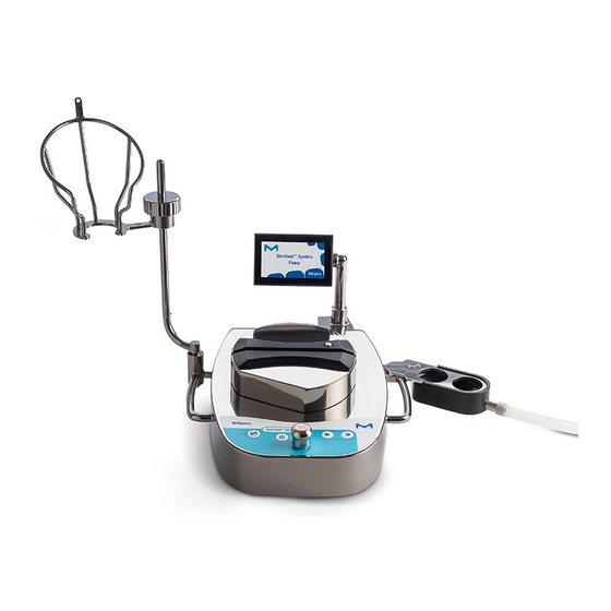
Overview of the ISL Pump Assembly NOTE Dimensions are in millimeters. - Page 12 The Steritest Symbio ISL pump assembly consists of: ™ • The pump upper part (accessible on the isolator table), including: • A control panel on the front • An adjustable color display at the back • A pump head located below a protective cover •...
- Page 13 Communication hub ― front view: On/off switch T 6.3A L 250V Fuse slot Overfill system USB port port Footswitch port Ethernet port Syringe support port Communication hub ― rear view: Pump connection cable Fuse slot T 3.15A L 250V Power inlet...
-
Page 14: Preparing To Install The Pump In The Isolator
The cutout details and the recommended position of the drain in relation to the cutout are indicated in the following drawing. NOTE The e-drawing file (.dxf) for this cutout is available at www.millipore.com/steritest-symbio. 6 holes 11mm Recommended area for placement of the drain... - Page 15 To ensure good flow of the liquid to the drain, the isolator table should be equipped with an elbow piece (oriented to the drain tray) to which the drain tubing can be connected. Elbow piece The height of the elbow piece should not exceed 50 mm to ensure that the drain tray is higher than this elbow piece.
- Page 16 The position of the cutout on the isolator table must be defined according to the dimensions and contents of the isolator in order to avoid any interference and improve ergonomics. The following drawing shows the size of the pump upper part (the part that is on the top of the isolator table), with its accessories, in relation to the cutout.
-
Page 17: Installation Recommendations
Symbio Pumps Isolator Installation Checklist (PF17360) to document ™ the proper execution of the installation steps and test cycles. (Download the checklist at www.millipore.com/steritest-symbio ) Deliver this document to the end user of the pump. Tools Required The following tools are required for the installation of the pump: •... -
Page 18: Unpacking The Equipment
Symbio Pump is delivered in two boxes that are strapped together. ™ STERITEST SYMBIO LFH 2 MEDIA Cat Nb: SYMBLFH01 Lot Nb: F4PN01234 LFH1 Millipore S.A.S 67120 Molsheim - Made in France The larger box contains: • Steritest Symbio Pump ™ • Communication hub •... - Page 19 • Quick guides (in German, English, Spanish, French, Italian, Portuguese, Japanese, Simplified Chinese, Russian, and Turkish): • Steritest Symbio Pump Startup Quick Guide ™ • Steritest Symbio Pump User Interface Quick Guide ™ • Steritest Symbio Software Quick Guide ™ To unpack the boxes: Using the carrying handles on the larger box, place the package on a flat, stable, and horizontal surface.
-
Page 20: Verifying That The Pump Functions Properly
Steritest Symbio Software User Guide are available at ™ www.millipore.com/steritest-symbio. Verifying that the Pump Functions Properly Before installing the pump, verify that it is functioning properly. Place the pump on its side and connect the communication hub pump connection cord to... - Page 21 Connect the communication hub to the power source using the power cord delivered with the pump. Switch on the communication hub by pressing the on/off switch (position l ). Main on/off switch T 6.3A L 250V Simultaneously press and hold the pump on/off and the open/close buttons.
- Page 22 When the autotest is complete, the following screen displays. A symbol in a check box indicates that an accessory or data source is connected to the communication hub. Press the button. The installation menu displays. Press the control knob to select Out of the box. The Out of the box screen displays.
- Page 23 Press the control knob to begin the test cycle. Only one cycle will be performed. After the pump head closes, the pump starts automatically, and 1 test cycle is performed. When the Test Cycle completes with no error, the following screen displays.
-
Page 24: Installing The Pump
Switch off the communication hub by pressing the on/off switch (position O). The Shutdown screen displays. Disconnect the communication hub pump connection cord from the pump power inlet. Proceed to the installation of the pump (see Installing the Pump). Installing the Pump NOTE This procedure applies to isolator tables that are up to 7 mm thick. - Page 25 Locate the 8 screws that secure the pump bottom plate to the pump. Use a T20 star screwdriver to remove the 8 screws. NOTE The cable that connects the pump power inlet to the electronic board is attached to the pump bottom plate.
- Page 26 Gently lift the pump bottom plate off the pump (1), disconnect the cable (2), and completely remove the bottom plate (3). Locate the main component of the pump and all the cables from the electronic board (located at the rear of the pump) and the cables from the rotor motor reducer driver (located at the front of the pump).
- Page 27 Electronic board simplified view: Rotor motor reducer driver view: 9 11a Disconnect the 3-pin connector (11a) and the 6-pin connector (11b) from the rotor motor reducer driver. Locate the cable holder that is attached to the pump housing at the right of the electronic board.
- Page 28 Disconnect the cables 3 and 4 from the main electronic board (see Electronic board simplified view). Locate the 3 screws on the rotor motor reducer block that secure the block to the pump. Screws...
- Page 29 Use a #3 hex key to unscrew and remove the 3 screws and washers. Remove the rotor motor reducer block from the pump. Rotor motor reducer block NOTE To facilitate the installation in the isolator, do not modify the position of the rotor motor reducer belt.
- Page 30 Gently pull this cable holder and release the cables. Disconnect cables 1, 2, and 8 from the main electronic board. Locate the 4 screws on the stator motor reducer block that secure it to the pump (see illustration above). Use a #3 hex key to unscrew and remove the 4 screws and washers. Remove the stator motor reducer block from the pump.
- Page 31 NOTE To facilitate the installation in the isolator, do not modify the position of the stator motor reducer belt. Disconnect cables 5, 6, 9, and 10 from the main electronic board (see Electronic board simplified view). Screws Locate the 5 screws on the pump housing that secure it to the pump. Screws...
- Page 32 Use a #5 hex key to unscrew and remove the 5 screws and washers. Lock washer Washer Locate the 2 screws that secure the electronic board to the pump housing (see the illustration below). Use a T20 star screwdriver to unscrew the 2 screws. Remove the electronic board from the pump housing.
- Page 33 Remove the pump housing. Pump housing Locate and remove the 3 spacers that protect the pump flat seal during storage and transportation. Flat seal NOTE Ensure that the flat seal is not damaged. If it is damaged, replace it (see Accessories and Replacement Parts).
- Page 34 Insert the two threaded stems delivered with the pump into the two M8 holes indicated in the following illustration: Turn the pump upper part right side up and place it above the isolator cutout. Make sure that all the cables and the electronic board go through the cutout. Center the pump by placing the two threaded stems in the dedicated holes of the cutout.
- Page 35 Place the pump housing under the isolator table. To center the pump housing, make sure the two threaded stems go through the corresponding pump housing holes, as shown in the illustrations. While holding the pump housing in place, use a #5 hex key to screw the 2 pump housing screws, with 2 washers each, as shown in the following illustration: Place the electronic board in its housing.
- Page 36 Remove the 2 threaded stems. Use a #5 hex key to install the 3 other pump housing screws, with washers. Perform a tightness test of the isolator before proceeding. If this test fails, ensure that all the 5 screws on the pump housing are properly installed, and ensure that the flat seal is not damaged.
- Page 37 NOTE Do not turn the coupling piece located at the bottom of the pump upper part. If the position of the stator motor reducer belt has not been modified during the disassembly step, the alignment should be okay. If necessary, turn the stator motor reducer belt to adjust the orientation of the coupling piece located on the stator motor reducer block.
- Page 38 Connect cable 1 to the electronic board. This cable is permanently attached to the pump upper part. It goes through the cable holder attached to the pump housing, and is connected to the electronic board.
- Page 39 Connect cable 2 to the electronic board. This cable comes from the stator motor reducer block. It goes through the cable holder attached to the pump housing, and is connected to the electronic board.
- Page 40 Connect cable 8 to the electronic board. This cable comes from the stator motor reducer block. It goes to the right of this motor reducer block, goes through the cable holder located at the right of the electronic board, then goes behind the electronic board, and is finally connected to the electronic board. Câble 8...
- Page 41 Connect cable 5 to the electronic board. This cable is permanently attached to the pump upper part. It goes through the cable holder attached to the pump housing, and is connected to the electronic board.
- Page 42 Connect cable 6 to the electronic board. This ribbon cable is permanently attached to the pump upper part. It goes to the right of the stator motor reducer block, goes through the cable holder located at the right of the electronic board, and is connected to the electronic board.
- Page 43 NOTE Do not turn the coupling piece located at the bottom of the pump upper part. If the position of the rotor motor reducer belt has not been modified during the disassembly step, the alignment should be okay. If necessary, turn the rotor motor reducer belt to adjust the orientation of the coupling piece located on the rotor motor reducer block.
- Page 44 Use a #3 hex key to install the 3 screws and washers to secure the rotor motor reducer block to the bottom of the pump upper part.
- Page 45 Connect cable 9 to the electronic board. This cable links the rotor motor reducer driver to the electronic board. From the motor reducer driver (2-pin connector), the cable goes behind this rotor motor reducer driver, then to the left of the rotor motor reducer block, then through the cable holder attached to the pump housing, and is connected to the electronic board.
- Page 46 Connect cable 10 to the electronic board. This cable links the rotor motor reducer driver to the electronic board. From the motor reducer driver (18-pin connector), the cable goes behind this rotor motor reducer driver, then to the left of the rotor motor reducer block, then through the cable holder attached to the pump housing, and is connected to the electronic board.
- Page 47 Connect the 3-pin connector (11a) and the 6-pin connector (11b) to their bases on the motor reducer driver. Cable 11 comes from the rotor motor reducer block, goes to the left of this motor reducer block, then goes behind the rotor motor reducer driver to which it is finally connected.
- Page 48 Connect cable 3 to the main electronic board. This cable is permanently attached to the pump upper part. It goes to the right of the stator motor reducer block, then through the cable holder located at the right of the electronic board, and is connected to the electronic board.
- Page 49 Connect cable 4 to the main electronic board. This cable comes from the rotor motor reducer block, goes to the right of the stator motor reducer block, then through the cable holder located at the right of the electronic board, and is connected to the electronic board.
- Page 50 Connect the power connector cable to the power connector located on the pump bottom plate, and then place the bottom plate under the pump housing. Use a T20 star screwdriver to install the 8 screws that attach the bottom plate to the pump housing.
- Page 51 Switch on the communication hub by pressing the on/off switch (position l ). Main on/off switch T 6.3A L 250V Simultaneously press and hold the pump on/off and the open/close buttons. The screen displays the range of Steritest devices. This is followed by the welcome ™...
- Page 52 When the autotest is complete, the following screen displays. A symbol in a check box indicates that an accessory or data source is connected to the communication hub. Press the button. The installation menu displays. Turn and press the control knob to select After Installation in Isolator.
- Page 53 Press the control knob. The After Installation in Isolator screen displays. Press the control knob to begin the test cycles. Three cycles will be performed. After the pump head closes, the pump starts automatically, and the 3 test cycles are performed.
- Page 54 When all three test cycles complete with no error, the Test Cycle OK screen displays. Switch off the communication hub by pressing the on/off switch (position O). The Shutdown screen displays. Disconnect the communication hub pump connection cord from the pump power inlet.
-
Page 55: Installing The Communication Hub Under The Isolator
Installing the Communication Hub under the Isolator Use the optional communication hub holder for isolators to install the communication hub under the isolator table (see Accessories and Replacement Parts). Multiple configurations are possible. Installing the Communication Hub on the Side, High Version Installing to the Left of the Pump Use the small screws and washers to attach the holder to the bottom of the communication hub. - Page 56 Installing to the Right of the Pump Use the small screws and washers to attach the holder to the bottom of the communication hub. Row 1 Row 2 Row 3 NOTE To install the communication hub in alignment with the pump housing (the default position), use the holes in row 2.
-
Page 57: Installing The Communication Hub On The Side, Low Version
Installing the Communication Hub on the Side, Low Version Installing to the Left of the Pump Use the small screws and washers to attach the holder to the bottom of the communication hub. Row 3 Row 2 Row 1 NOTE To install the communication hub in alignment with the pump housing(the default position), use the holes in row 2. - Page 58 Installing to the Right of the Pump Use the small screws and washers to attach the holder to the bottom of the communication hub. Row 3 Row 2 Row 1 NOTE To install the communication hub in alignment with the pump housing (the default position), use the holes in row 2.
-
Page 59: Installing The Communication Hub Below The Pump Housing
Installing the Communication Hub below the Pump Housing Use the small screws and washers to attach the holder to the bottom of the communication hub. Row 3 Row 2 Row 1 NOTE To install the communication hub in alignment with the isolator (the default position), use the holes in row 2. -
Page 60: Accessories And Replacement Parts
Accessories and Replacement Parts Quantity Description Catalog Number per pack Steritest™ Symbio Pump Steritest™ Symbio ISL Pump Kit, 2 media SYMBISL01WW* Steritest™ Symbio Pump Services Steritest™ Symbio pumps validation protocol (A4 format) SYMBA4VP1 Steritest™ Symbio pumps validation protocol US (letter format) SYMBLTVP1 NOTE: Contact our sales representative or Technical Service for more information about our application support, validation services, maintenance, and repair services. - Page 61 Power cord for Italy SIMCABLE9 Power cord for Brazil SIMCABLE11 Steritest™ Symbio flat seal for ISL pump SYMBFSI01 Software (Available at www.millipore.com/steritest-software) Steritest™ Symbio Software ― ― Consumables Visit our website or contact Steritest™ devices, culture media and rinsing fluids ―...
-
Page 62: Symbols Referenced
Electric and Electronic Equipment (WEEE), the presence of this logo on the product indicates that it should not be disposed of in the normal waste stream but collected separately. Go to www.millipore.com/weee for details on how to ensure proper treatment of the product in different countries. -
Page 63: Standard Product Warranty
(before and after installation) described in this installation guide. Use the Steritest Symbio Pumps Isolator Installation Checklist (PF17360) to document ™ the proper execution of the installation steps and test cycles. (Download the checklist at www.millipore.com/steritest-symbio ) Deliver this document to the end user of the pump. -
Page 64: Technical Assistance
For more information visit www.millipore.com/techservice Millipore, the M mark, Sterisolutest, and Steridilutor are registered trademarks of Merck KGaA, Darmstadt, Germany. Steritest is a trademark of Merck KGaA, Darmstadt, Germany. PF16599 Version 3.0 08/2017 © 2017 Merck KGaA, Darmstadt, Germany. All rights reserved.
Need help?
Do you have a question about the Steritest Symbio ISL and is the answer not in the manual?
Questions and answers