Table of Contents
Advertisement
Quick Links
WARNING
Improper installation, adjustment, alteration, service
or maintenance can cause property damage, injury or
death. Read the installation, operating and
maintenance instructions thoroughly before installing
or servicing this equipment.
OWNER
Retain this Manual & ensure available for service.
Improper installation, adjustment, alteration, service
or maintenance can cause injury, death or property
damage.
Read the installation, operation and service
instructions thoroughly before installing or servicing
this equipment
Series BRL40
Installation, Operation and Service Instructions
INFRARED BROODER
Canada: 563 Barton Street, Stoney Creek, Ontario L8E 5S1
USA: 315 N Madison Street, Fortville, IN 46040
www.superiorradiant.com
Page 1
FOR YOUR SAFETY
Do not store or use gasoline or other flammable vapors
and liquids in the vicinity of this or any other appliance.
If you smell gas:
1. Open windows
2. Don't touch electrical switches
3. Extinguish any open flame
4. Immediately call your gas supplier
INSTALLER
Provide Manual to Owner upon completion of
installation!
Read and thoroughly understand these Instructions
before attempting any installation
SERIES
BRL40
LT234 August 2019
Advertisement
Table of Contents

Subscribe to Our Youtube Channel
Related Manuals for SRP BRL40 Series


Summary of Contents for SRP BRL40 Series
- Page 1 Installation, Operation and Service Instructions INFRARED BROODER SERIES BRL40 WARNING FOR YOUR SAFETY Improper installation, adjustment, alteration, service Do not store or use gasoline or other flammable vapors or maintenance can cause property damage, injury or and liquids in the vicinity of this or any other appliance. death.
- Page 2 WARNING: FIRE OR EXPLOSION HAZARD Maintain clearance to combustible constructions as further specified in this manual. Failure to do so could result in a serious fire hazard. Heaters should not be located in hazardous atmospheres containing flammable vapors or combustible dusts. Signs should be provided in storage areas specifying maximum safe stacking height.
-
Page 3: Table Of Contents
ONTENTS CONTENTS ..................................... 3 INTRODUCTION ..................................4 ..................................4 NSTALLATION ODES GENERAL SPECIFICATIONS ..............................5 ......................................5 NPUT ....................................5 UPPLY .................................... 5 LECTRIC UPPLY ....................................5 ENTILATION ................................5 HIPPING CONFIGURATION ................................. 5 LTITUDE ATINGS DIMENSIONAL CHARTS ................................5 BROODER PARTS .................................. -
Page 4: Introduction
INTRODUCTION Superior Radiant Products is a company in the infrared heating industry founded on the principles of product quality and customer commitment. Quality commitments are evidenced by superior design, a regard for design detail and an upgrade of materials wherever justifiable. Customer commitment is apparent through our ready responses to market demands and a never ending training and service support program for and through our distributor network. -
Page 5: General Specifications
GENERAL SPECIFICATIONS Input 40,000 BTU/hr Gas Supply Inlet Pressure Natural Gas: Minimum 5.0” W.C. Propane Gas: Minimum 11.0” W.C. Maximum 14.0” W.C. Maximum 14.0” W.C. Manifold Pressure 4” W.C. Natural Gas: Propane Gas: 10” W.C. Inlet Connection Natural Gas or Propane: 3/8” female NPT Electric Supply 24 VAC, 60 HZ, 0.8 Amp Ventilation... -
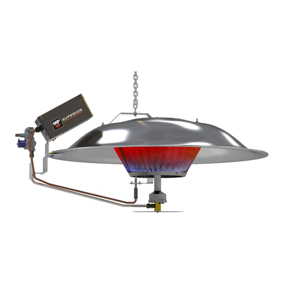
Page 6: Brooder Parts
BROODER PARTS Get to know your heater parts (list referencing Figure 2). Figure 2: General Overview Series BRL40 Page 6 LT234 August 2019... -
Page 7: General Assembly
General Assembly Refer to Figure 2 for component identification. Description Description Screw S/S #8-32x3/8” Pan Phillips BS014 Brooder Main Hanging Bracket CH118 Washer, Flat 3/16 x 3/4” CH095 BE008 Control Box Assembly BS001 Dust Pan BS012 Control Box Mounting Bracket BG005 Brass Adapter BS011... -
Page 8: Package Contents
PACKAGE CONTENTS The radiant brooder is sold in packages of six or one, depending on the customer’s quantity order. Verify that you have received all heater components included with the unit. The unit is packaged as sub-assemblies in kits, listed below. -
Page 9: Clearance To Combustibles
CLEARANCE TO COMBUSTIBLES Minimum clearances to combustible materials shall be measured from outer surface of the reflector. In addition to this it is very important to observe the minimum clearance to combustibles at all times to avoid any possibility of property damage or personal injury. Combustible materials are considered to be wood, compressed paper, plant fibres, plastics, Plexiglas or other materials capable of being ignited and burned. -
Page 10: Assembly
ASSEMBLY 1. Before assembling, check that all components are included in the package. 2. Fasten the burner assembly to the cone assembly using three (3) #10-24 hex locknuts, and attach the igniter bracket to the burner assembly using a #10-24 hex locknut, as shown in Fig. 6. Figure 6 3. - Page 11 4. Attach the heat shield and control box mounting bracket to the reflector at the alignment holes, using two (2) ¼-20 S/S bolts, nuts and washers. 5. Attach the gas manifold assembly by securing the T-clamp over the tube, covering up to the gas fitting. Insert the orifice block into the bottom of the burner and use the swivel clamp to hold it in place.
- Page 12 Figure 10 8. Mount the control box onto the bracket, securing it with two (2) #10-24 locknuts. Figure 11 9. Attach the wiring as shown in the wiring diagram (see ELECTRICAL CONNECTIONS section below), Plug the ignition cable into the igniter, then secure the boot over the igniter. After attaching the ignition cable to the igniter, secure the cable to the gas tube with zip ties.
- Page 13 For gas valve BG003 For gas valve BG003 (alternate wiring) 10. The blue wires coming from the control box 10. The gas valve has two (2) blue leads and two (2) red connect to the gas valve, follow the diagram below leads.
-
Page 14: Installation
INSTALLATION WARNING NEVER USE THE GAS HOSE AS A SAFETY CHAIN 1. Hang the brooder at the appropriate height above the floor (litter) level, approximately 65”-75” (1650mm- 1900mm). When using a winch, use a cable or chain suitable for the weight of each brooder. DO NOT USE ROPE. -
Page 15: Venting & Combustion Air
VENTING & COMBUSTION AIR General Requirements ATTENTION VENTILATION REQUIREMENTS BE SURE THE AIR INLET GRILLS, LOUVERS AND DAMPERS ARE INSPECTED REGULARLY AND THAT THEY ARE CLEAR AND FREE OF DUST, DIRT, SNOW, ICE, FROST AND OTHER FOREIGN MATERIAL SO THAT AIR MAY FREELY ENTER INTO THE BUILDING TO PROVIDE ADEQUATE COMBUSTION AND VENTILATING AIR. -
Page 16: Gas Piping
GAS PIPING The gas meter and service must be sufficiently large to supply gas to the connected building gas load including the heating equipment and any other gas fired equipment. Additionally, the gas distribution piping must be designed according to local and national ordinances. Generally (low pressure) systems designed with a maximum ½"... - Page 17 WARNING FIRE HAZARD Tighten flexible gas hose and components securely. Flexible gas hoses must be installed without any twists or kinks in them. DO NOT allow the hose to touch any part of the brooder canopy during operation Failure to do so may result in death, serious injury or property damage ...
-
Page 18: Electrical Connections
ELECTRICAL CONNECTIONS Wiring diagram All fields wiring to the brooder must be done in accordance with the National Electric Code, ANSI/NFPA 70 in the USA, and the Canadian Electric Code, CSA C22.1 in Canada, and must comply with all local requirements. The brooder must be electrically grounded. - Page 19 Figure 17a: Wiring Diagram for gas valve BG003 (alternate wiring) BLUE BLUE Figure 17b&c: WAGO lever connectors are used with gas valve BG003, which has its own leads Series BRL40 Page 19 LT234 August 2019...
-
Page 20: Lighting And Shutdown Instructions
The brooder is designed to operate on an external 24VAC electrical system. Provide only 24VAC with a Class 2 transformer, field supplied, to the control wires. The transformer size depends on the number of brooders controlled in the same time. Transformer Size = No. -
Page 21: Fuel Conversion Kit
FUEL CONVERSION KIT The brooder from the factory is equipped to run on propane, but can be modified to run on natural gas with the conversion kit supplied. The conversion kit, P/N BK014, contains the following: BL021 - BRL40 Natural Gas sticker UG032 - Orifice #32 BL022 - Conversion Label BRL40 LT260 - Conversion Instruction Sheet BRL40... - Page 22 4. Remove the orifice with a 1/2” wrench, then clean out the threads of the orifice block with a wire brush 1/2” Figure 20 5. Apply pipe thread sealant rated for LP gas to the new orifice #32, and then install it into the orifice block with a 1/2”...
-
Page 23: Maintenance
Maintenance Annually ask your gas supplier to: Check all gas piping annually for leaks or restrictions in gas lines. Clean out the sediment trap. Check for gas leaks and proper function of regulators. Note: Before performing any services or maintenance, shut off gas and electrical supply to heater. ... -
Page 24: Troubleshooting
TROUBLESHOOTING 1. IGNITION MODULE DIAGNOSTICS LED Indication Fault Mode Steady On Internal Control Failure 2 Flashes Flame without call for heat 3 Flashes Ignition Lockout 2. FLAME CURRENT MEASUREMENT The flame current passes through the flame from the sensor and to the ground. The flame current necessary to keep the system from lockout should be 1.0 μA DC or higher. -
Page 25: Replacement Parts
REPLACEMENT PARTS ITEM DESCRIPTION PART NUMBER Ignition control BE002 On/Off switch BE007 Gas valve 25M18-716 BG003 Gas Tubing with fittings BG021 Burner orifice – Propane UG029 Burner orifice – Natural gas UG032 Ignition cable BE004 Electrode BE003 Emitter Assembly BS006 WAGO 3 Conductor Lever Nut CE280 Series BRL40... -
Page 26: Warranty
WARRANTY SERIES BRL INFRARED HEATERS WARRANTY The manufacturer warrants to the original owner that the product will be free of defects in material and workmanship as described below. COMPONENT WARRANTY PERIOD Burner & Controls 3 Years Reflector 7 Years The Manufacturer’s obligation under this warranty is limited to repair or replacement, F.O.B. its facility, of the defective part.
Need help?
Do you have a question about the BRL40 Series and is the answer not in the manual?
Questions and answers