
Related Manuals for Stealth Products IDHBT500

Summary of Contents for Stealth Products IDHBT500
- Page 1 Install Manual IDHBT500, IDHBT500-1, IDHBT500-17 i-Drive 4.0 with Bluetooth® Wireless Technology INSTALLATION INSTRUCTIONS FOR Stealth Products i-Drive 4.0 ® interface with Bluetooth wireless technology...
- Page 2 Customer Satisfaction Stealth Commitment Stealth Products strives for 100% customer satisfaction. Your complete satisfaction is important. Please contact us with feedback or suggested changes that will help improve the quality and usability of our products. You may reach us at:...
-
Page 3: Fcc Statement
This device must accept any interference received, including interference that may cause undesired operation. FCC Warning Changes or modifications not approved by Stealth Products, LLC could void the user’s authority to operate the equipment. Note: This equipment has been tested and found to comply with the limits for Class B digital device, pursuant to part 15 of the FCC rules. -
Page 4: Important Information
Important Information Important Information! All persons responsible for fitting, adjustment, and daily use of the devices discussed in these instructions must be familiar with and understand all safety aspects of the devices mentioned. In order for our products to be used successfully, you must: ... -
Page 5: Table Of Contents
8.2 i-Drive Bluetooth Minimum System Requirements ........ 5 8.3 EMC Requirements ....................5 8.4 Control System Overview .................. 6 9.0 Installation Instructions ................7 9.1 Replacing/Installing Dongles ................7 9.2 Uninstalling/Replacing IDHBT500 ..............10 9.3 Uninstalling/Replacing IDHBT500-1 ............12 9.4 Uninstalling/Replacing IDHBT500-17mm ..........16... - Page 6 Table of Contents 10.0 Calibration .................... 19 10.1 Chair Calibration ....................19 10.2 Joystick Calibration ..................22 10.3 Calibration Verification ................... 24 11.0 R-Net Installation ................25 11.1 R-Net Omni Installation ................. 25 Setup ........................26 12.0 Q-Logic Installation ................28 12.1 Q-Logic Setup ....................
- Page 7 Table of Contents 13.9 Running Real Time Diagnostics ..............41 Diagnostics Feature ..................41 13.1.0 Help Feature....................42 13.1.1 Closing the i-Drive Programming Software ........43 14.0 i-Drive Mobile App Installation............44 14.1 Downloading the i-Drive Bluetooth® Application ........ 44 For iPhone®...
-
Page 8: Warnings
SAFETY necessary. Limited Liability Stealth Products, LLC accepts no liability for personal injury or damage to property that may arise from the failure of the user or other persons to follow the recommendations, warnings, and instructions in this manual. Stealth Products does not hold responsibility of final integration of final assembly of product to end user. -
Page 9: Index
Index Index Configurable Parameters-There is only one additional configurable parameter in the i-Drive configuration application for switched inputs, sensor sensitivity. Sensor Sensitivity–This parameter shifts the position of the switch no-change region. A higher value therefore means that a switch will always be interpreted as ON, whereas a lower value means that a switch will almost always be interpreted as OFF. -
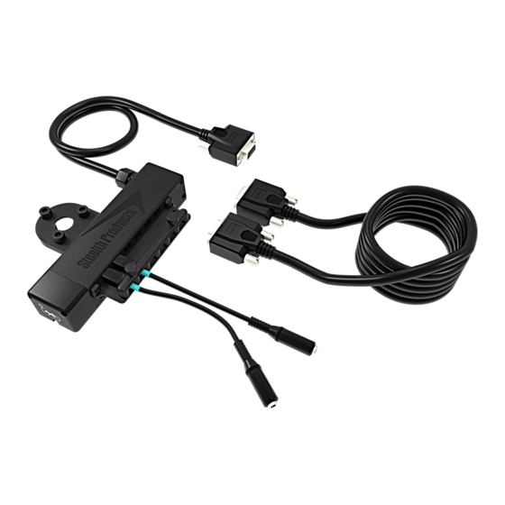
Page 10: Parts And Accessories
Parts and Accessories Hardware Packages/Parts Description A IDHBT500 A1 M5 x .8 x 6mm BHS* (2) A2 Power Cable A3 Female Mono Dongles (2) Description B IDHBT500-1 M5 x .8 x 6mm BHS* (2) Comfort Ring Mount #10-32 x 3/4” SHS* (3) -
Page 11: Mounting Hardware Tools
Parts and Accessories Description C IDHBT500-17 M5 x .8 x 6mm BHS* (2) SU100 Ring Mount #10-32 x 1” SHS* (4) Power Cable Female Mono Dongles (2) Mounting Hardware Tools Tools* Description 1/8 T-Handle A1, C1 3/16 T-Handle B3, C3 2.5mm T-Handle... -
Page 12: Torque Specifications
Parts and Accessories Torque Specifications Item Torque Specification #10-32 x 3/4” SHS 90in-lb #10-32 x 1” SHS 34in-lb Port Assignment USB Port for configuration on PC Port Direction Assignment Left Forward Mode/Reset None Reverse Right The i-Drive 4.0 has the capability of taking inputs from mechanical switches, proximity sensors, fiber optic sensors, joysticks, and Sip &... -
Page 13: System Requirements
System Requirements i-Drive Minimum System Requirements Processor 1 GHz RAM1 512 MB Disk Space 7 MB Operating System 1 Windows Vista SP2 or later (32-bit or 64-bit) Additional Requirements Internet access and a valid DAD account for configuration features, .NET Framework 4.5.1 i-Drive Bluetooth Minimum System Requirements Processor 1 GHz... -
Page 14: Control System Overview
System Requirements Control System Overview The i-Drive system operates in different modes, including RUN & CONFIG modes. In RUN mode, no settings changes are allowed and computed outputs are sent to the chair. In CONFIG mode, settings changes are allowed and computed outputs are not sent to the chair. -
Page 15: Installation Instructions
Step 2: Slightly pull on the end of the dongle (C5) to disconnect from the port on the interface box. WARNING When reattaching the dongle, check diagnostics to ensure the dongle is reading correctly. NOTICE Ensure you have identified where each switch is located in the port before unplugging or replacing. * IDHBT500-17 shown as reference for this section. - Page 16 Installation Instructions To reattach dongles: Step 1: Locate the proper port each dongle/sensor needs to be plugged in to. Step 2: Before plugging in sensor or dongle, check that the arrow at the end of the cable is facing upward.
- Page 17 Installation Instructions Step 3: Plug each sensor/dongle (C5) into ports. Slightly pull the cable to ensure it has been securely placed into port. Step 4: Once the sensors are installed, locate the carrier plate with the thumb screws. Install the carrier plate into place by tightening the thumb screws.
-
Page 18: Uninstalling/Replacing Idhbt500
Mounting the IDHBT500 to IDHBT500-1 Step 1: Using a 2.5mm T-Handle, loosen the two (2) M5 x .8 x 6mm BHS from the IDHBT500-1. It is not required to removed the ball mount from the headrest to replace the IDHBT500. - Page 19 Mounting the IDHBT500 to IDHBT500-17mm Step 1: Using a 2.5mm T-Handle, loosen the two (2) M5 x .8 x 6mm BHS from the IDHBT500-17mm. It is not required to removed the ball mount from the headrest to replace the IDHBT500.
-
Page 20: Uninstalling/Replacing Idhbt500-1
Installation Instructions Uninstalling/Replacing IDHBT500-1 To uninstall the ball kit and interface: Step 1: With a 3/16 T-Handle, loosen the three #10-32 x 3/4” socket head screws (B3) completely from the back of the headrest. NOTICE It may be easier to remove the headrest from the client’s chair to do maintenance or replace the interface. - Page 21 Installation Instructions Step 2: With a 2.5mm T-Handle, remove the M5 set screw taper completely from the assembly. Step 3: Loosen and remove the M5 set screw from the ball kit with a 2.5mm T-Handle. Step 4: Once both set screws have been removed, the ball will freely move.
- Page 22 To reinstall the interface and ball kit: Step 1: The 1” ball will go through the IDHBT500-1 interface mounting plate and into the hardware bracket. Step 2: Ensure the M5 set screw taper is flush with the top of the bracket for proper installation.
- Page 23 Installation Instructions Step 4: Locate the three (3) #10-32 mounting screws (B3). Tighten screws evenly onto the headrest until snug and place the headrest back onto the client’s chair. Refer to Section 4.4 for proper torque specifications. CAUTION Tighten screws evenly on the hardware. Damage could occur to the hardware If the screws aren’t secured evenly.
-
Page 24: Uninstalling/Replacing Idhbt500-17Mm
Installation Instructions Uninstalling/Replacing IDHBT500-17mm To remove the interface and ball kit: Step 1: With a 3/16 T-Handle, loosen the four #10-32 socket head screws (C3). Step 2: Remove the screws completely from the back of the headrest. 17mm hardware is compatible with the Pediatric Comfort Plus, All Positioning, Combo,... - Page 25 Installation Instructions Step 3: Loosen the 10-32 x 1” SHS from the ring mount (C2). CAUTION Removing the screws will cause the ring mount and interface to drop from the headrest. Use caution when removing. NOTICE Ensure all switches and dongles are disconnected from the interface to avoid damages to ports or connectors.
- Page 26 Installation Instructions Step 5: Locate the four (4) #10-32 mounting screws (C3). Tighten screws evenly onto the ring mount until snug and place the headrest back onto the client’s chair. Step 6: Position the headrest appropriately on the client’s chair. Once positioned, tighten the #10-32 (4) mounting screws.
-
Page 27: Calibration
Calibration 10.0 To get the best performance from the i-Drive, calibration is required. It is important to note that calibration of the wheelchair to i-Drive is required even if i-Drive is using switched inputs. NOTICE In all cases, calibration can only be done by a user with appropriate access granted. - Page 28 Calibration 10.0 DANGER Calibration should be done without the user in the chair. WARNING To prevent motion during calibration, disengage the motors of the power chair before calibrating. Connect to the i-Drive and login using your username and password with configuration access.
- Page 29 Calibration 10.0 Enter Chair Calibration mode using the i-Drive Configuration App. During this step, the i-Drive is commanded to output a calibration sequence to the wheelchair. This sequence is equivalent to rotating a joystick counter-clockwise in two full circles. One completed, the i-Drive returns to the configuration screen.
-
Page 30: Joystick Calibration
Calibration 10.0 Joystick Calibration 10.2 To calibrate a joystick, at least one input channel must be assigned to Proportional Forward/Reverse or Proportional Left/Right. If only one is assigned then the calibration procedure only calibrates the assigned one. If both are assigned then the calibration procedure calibrates both. - Page 31 Calibration 10.0 If Proportional Forward/Reverse is assigned: Tilt the joystick full forward until the time bar expires. Tile the joystick full reverse until the time bar expires. If Proportional Left/Right is assigned: Tilt the joystick full left until the time bar expires. Tilt the joystick full right until the time bar expires.
-
Page 32: Calibration Verification
Calibration 10.0 Joystick calibration is now complete. The app will return to the configuration screen. Calibration Verification 10.3 To verify the calibration of a joystick, first disengage the wheelchair motors. Enter Diagnostic mode. Move the joystick and verify that the diagnostic bars mirror the motion of the joystick. -
Page 33: R-Net Installation
R-Net Installation 11.0 The i-Drive plugs into the 9 pin port on the power chair’s control interface. The location of the port depends on the manufacturer of the interface. Follow the instructions for your interface manufacturer in these next sections. R-Net™... -
Page 34: Setup
R-Net Installation 11.0 WARNING Please manually disengage both drive motors before utilizing the Setup Wizard, Diagnostics, and Config. If motors are not disengaged, the chair could move during setup. Setup Power off the chair with the power button on the joystick or display. Disengage the motors before programming the chair. - Page 35 R-Net Installation 11.0 14. Wait until the calibration finalizes. Your chair display will show a green checkmark meaning calibrations was a success. 15. On the Omni display you will need to exit the OBP menu and power the chair off. Now you will be able to set up the chair as required.
-
Page 36: Q-Logic Installation
Q-Logic Installation 12.0 Q-Logic™ Setup 12.1 Bookmark Buttons Select Options in the main menu. Button actions are displayed on screen above corresponding buttons. In other menus, hold button to Bookmark Settings, and press button to quickly go to bookmark. Navigation Arrows navigate the main menu. -
Page 37: Setup For Q-Logic 2
Q-Logic Installation 12.0 WARNING Please manually disengage both drive motors before utilizing the Setup Wizard, Diagnostics, and Config. If motors are not disengaged, the chair could move during setup. Setup for Q-Logic 2 Power off the chair with the power button on the joystick or display. Disengage the motors before programming the chair. - Page 38 Q-Logic Installation 12.0 11. The Q-Logic programmer will read, Roll around joystick in two full circles. 12. Go to the i-Drive application on the Phone/Tablet/PC Device. Select Config Chair tab. Select Calibrate Chair. Click Okay. 13. Wait until the calibration finalizes, then select Okay with the Q-Logic programmer and verify the calibration was successful.
-
Page 39: Setup For Q-Logic 3
Q-Logic Installation 12.0 Setup for Q-Logic 3 Power off the chair with the power button on the joystick or display. DANGER Disengage the motors before programming the chair. Ensure all the cords from the display are properly connected to the chair. Connect the i-Drive 9-pin connection into the port on the bottom of the Enhanced Display. -
Page 40: Q-Logic Drive Control System Further Configuration
Q-Logic Installation 12.0 Q-Logic™ Drive Control System Further Configuration 12.3 Back Pad Toggle If you want to disable or enable the back pad’s ability to toggle into forward and reverse: Reconnect the Q-Logic Handheld Programmer. Follow Steps 1-7 from Setup. On the Q-Logic Programmer, select the Program Adjustments option. -
Page 41: Egg Switch Function
Q-Logic Installation 12.0 Egg Switch Function If you would like to change the function of the egg switch to Mode or Toggle Forward and Reverse: Reconnect the Q-Logic Handheld Programmer (follow Steps 1-7 from Setup). On the Q-Logic Programmer, select Program Adjustments option. In the Program Adjustments menu, with the Up &... -
Page 42: Advanced Programming Software
Downloading the i-Drive Software 13.3 To program the i-Drive from your PC, the Advanced Programming Software™ will need to be downloaded from the Stealth Products website: https://stealthproducts.com/idrive/download/ The USB interface enables an external device to communicate with i-Drive with the use of a virtual communications port. There is no authentication... - Page 43 Bluetooth connection. *PC views shown. WARNING To ensure security on your i-Drive, contact Stealth Products to obtain your user name and password for the software. In order to connect to the i-Drive to the software, the serial number from the interface must be entered.
-
Page 44: Connecting To The I-Drive
Advanced Programming Software 13.0 Connecting To The i-Drive 13.4 After adequate time is given to allow the i-Drive to connect to your computer and you have launched the application, click the Connect button. NOTICE If may be required to change the COM in the drop-down menu next to the Connect button. -
Page 45: Running The Setup Wizard
Advanced Programming Software 13.0 Running The Setup Wizard 13.5 Setup Wizard will guide you through the initial configuration and channel assignment of the i-Drive. To begin the Setup Wizard, click the Setup Wizard button on the left of the screen. Setup Wizard Feature The Setup Wizard will guide you through the initial port configuration and channel assignment of the i-Drive. -
Page 46: I-Drive Configuration Settings
Advanced Programming Software 13.0 i-Drive Configuration Settings 13.6 To begin the configuration, click the Config Mode button on the left of the screen. Configuration Feature Configuration allows you to adjust the way the i-Drive activates and allows you to fine tune the function and sensitivity of the sensor/joystick/chair. Sensor Channels Tab–... -
Page 47: Configuration: Sensor Channels
Advanced Programming Software 13.0 Configuration: Sensor Channels 13.7 1-Diagram shows channel switches and channels currently in use 2-Drop down menus that allow you to assign function to each channel 3-Channel Deadband slider that allows sensitivity change of deadband 4-Changes the channel of which the deadband has been adjusted NOTICE Channels that are not being used will appear in red on the screen. -
Page 48: Configuration: Double Tap Setting
Advanced Programming Software 13.0 Configuration: Double Tap Settings 13.8 A. Double Tap-Enabling Double Tap allows for adjustment of Double Tap input and output timing B. Double Tap Input Delay– Amount of time for Double Tap command capture C. Double Tap Output Speed– Time period between Mode output pulses. This value should match the Double Tap Input Timing of the chair NOTICE It is recommended to use Calibrate Double Tap option in the Diagnostics to get... -
Page 49: Running Real Time Diagnostics
Advanced Programming Software 13.0 Running Real Time Diagnostics 13.9 To begin the Diagnostics, click the Diagnostics button on the left of the screen. Mode Switch activation Left, Right, Forward & Reverse activation Corresponding i-Drive port when switch is pressed Double Tap Calibration Diagnostics Feature With real time Diagnostics, you are able to observe pad behavior as the head array is activated by the user. -
Page 50: Help Feature
Advanced Programming Software 13.0 Help Feature 13.1.0 Clicking the Help button will activate help. When Help is active, the help button will be green and a question mark (?) will be displayed next to your cursor. With Help active, clicking buttons and menu items will pop up with an explanation of what the clicked object is and how it can be utilized. -
Page 51: Closing The I-Drive Programming Software
Advanced Programming Software 13.0 Closing the i-Drive Programming Software 13.1.1 When you are finished configuring the i-Drive, you can click on the Quit button on the bottom right of the screen to close the application. -
Page 52: I-Drive Mobile App Installation
i-Drive Mobile App Installation 14.0 ® Downloading the i-Drive Bluetooth Application 14.1 ® For iPhone Users: Search, “Trident Research, LLC” in the Apple® App Store® Install the App and then “Open” once App has been successfully installed on your phone. -
Page 53: For Android Users
i-Drive Mobile App Installation 14.0 For Android Users: Search “Trident Research, LLC” in the Play Store Select “Install” and then “Open” when the App has been successfully installed on your phone. -
Page 54: Opening The I-Drive App
i-Drive Mobile App Installation 13.0 Opening the i-Drive App 14.2 A battery, battery charger, dongle cable, and a 9-pin pig tail plugged into the USB port on the interface is required in order to connect the i-Drive to your phone. To Log In, enter the User Name and Password assigned to you. -
Page 55: Config Mode
i-Drive Mobile App Installation 13.0 Config Mode 14.3 In the Main Menu, Select Config Mode (Figure 3). Like the Advanced Programming Software on your PC or tablet, channel assignments, double tap settings, and other sensor settings are adjusted here. Under the Name section, you have the option of renaming your i-Drive. Changing the name of your i-Drive will require a power cycle. -
Page 56: Channel Assignment Settings
i-Drive Mobile App Installation 13.0 Channel Assignment Settings Within the channel option chosen, you will see a list of modifications and assignments that can be made to the channel. To select the assignment for the channel, click on the assignment. To go back to the channel options, click back on the upper left hand corner. -
Page 57: Multi-Tap Setting
i-Drive Mobile App Installation 13.0 Multi-Tap Setting To activate the Multi-Tap function, select Multi-Tap in the Config Mode menu. Under the Multi-Tap setting, Input Delay and Output Speed can be adjusted. Move the cursor to the right or left to make adjustments. (Figure 7) When adjustments have been made, select the Save option in the upper right hand corner. -
Page 58: Diagnostics
i-Drive Mobile App Installation 13.0 Diagnostics After channel assignments and any other modifications necessary have been made, go back to the Main Menu. Select Diagnostics in the Main Menu. Test the assignments on your i-Drive device by activating each channel. When the direction assigned to the channel has been activated, the direction should light up in green. -
Page 59: Programming Seating Functions
Programming Seating Functions 15.0 Programming Seating Functions 15.1 R-Net To setup the chair’s seating functions, follow the instructions below: Reconnect the R-Net programming dongle. On the Omni display, enter into the OBP menu. In the OBP menu, navigate with the UP & Down buttons and select Omni with the Right button. -
Page 60: Warranty
16.0 Our products are designed, manufactured, and produced to the highest of standards. If any defect in material or workmanship is found, Stealth Products will repair or replace the products at our discretion. Any implied warranty, including the implied warranties of merchantability and fitness for a particular purpose, shall not extend beyond the duration of this warranty. - Page 61 NOTES 17.0...
- Page 62 NOTES 17.0...
- Page 63 NOTES 17.0...
- Page 64 Stealth Products, LLC. • info@stealthproducts.com • www.stealthproducts.com +1(800) 965-9229 | +1(512) 715-9995 | 104 John Kelly Drive, Burnet TX 78611 P137D453 Revision Date 2019-12-17...
Need help?
Do you have a question about the IDHBT500 and is the answer not in the manual?
Questions and answers