Table of Contents
Advertisement
Quick Links
Advertisement
Table of Contents

Subscribe to Our Youtube Channel
Related Manuals for Michell Instruments CDP301

Summary of Contents for Michell Instruments CDP301
- Page 1 CDP301 – Condumax Dew-Point Tester User’s Manual 97585 Issue 1 June 2020...
- Page 2 Please fill out the form(s) below for each instrument that has been purchased. Use this information when contacting Michell Instruments for service purposes. Analyzer Code Serial Number Invoice Date Location of Instrument Tag Number Analyzer Code Serial Number Invoice Date...
- Page 3 © 2020 Michell Instruments This document is the property of Michell Instruments Ltd and may not be copied or otherwise reproduced, communicated in any way to third parties, nor stored in any Data Processing System without the express written authorization of Michell Instruments Ltd.
-
Page 4: Table Of Contents
CDP301 Dew-Point Tester User’s Manual Contents Safety ..........................vii Electrical Safety .........................vii Pressure Safety .........................vii Toxic Materials ........................vii Repair and Maintenance .....................vii Safety Conformity ......................vii Abbreviations ........................viii Warnings .......................... viii INTRODUCTION ....................1 Sample Gas Path ..................... 1 Operating Overview ....................2 User Display and Interface .................. - Page 5 CDP301 Dew-Point Tester User’s Manual 5.3.3 Removing Particulates ................. 39 5.3.4 Removing Residue ..................40 5.3.5 Reassemble Sample Cell ................40 5.3.6 Check Mirror Cleanliness ................41 Figures Figure 1 Dimensions and Gas Connections ..............4 Figure 2 Michell Sample System ..................8 Figure 3 Menu Map ....................
- Page 6 CDP301 Dew-Point Tester User’s Manual 97585 Issue 1, June 2020...
-
Page 7: Safety
Repair and Maintenance The instrument must be maintained either by the manufacturer or an accredited service agent. For Michell Instruments’ contact information please go to www.michell.com. Safety Conformity This product meets the essential protection requirements of the relevant EU and US standards and directives. -
Page 8: Abbreviations
CDP301 Dew-Point Tester User’s Manual Abbreviations The following abbreviations are used in this manual: barg pressure unit (=100 kP or 0.987 atm) (bar gauge) ºC degrees Celsius ºF degrees Fahrenheit direct current grams inch(es) µm micrometer m/sec meters per second... -
Page 9: Introduction
Exd enclosure. A sample gas handling system to prepare the gas sample prior to entry into the CDP301 Dew-Point Tester can also be supplied. The Dew-Point Tester is designed to be positioned close to the process sample test point and is ATEX, IECEx and cQPSus compliant for use in a Zone 1 or 2 Hazardous Area and Class I, Div 1 Hazardous Locations. -
Page 10: Operating Overview
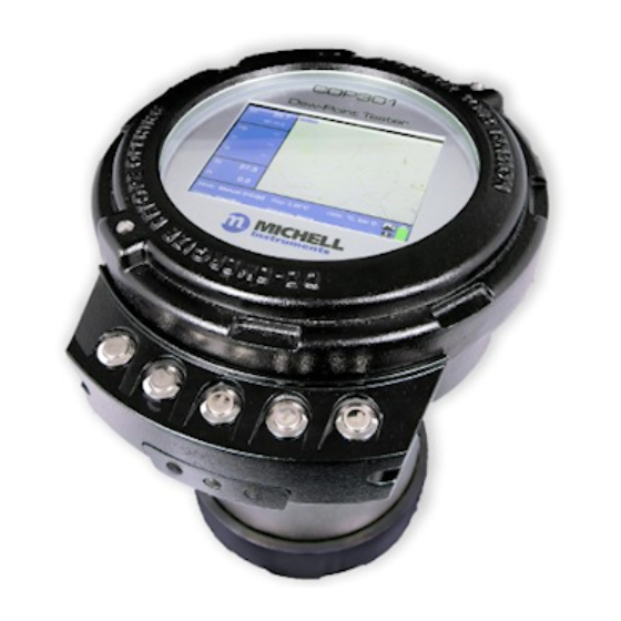
User Display and Interface The CDP301 Display and User Interface (UI) is presented via the circular window of the enclosure. The unit is operated using 5 buttons, which allows full control of the UI. The cover is fully detachable for greater access into the enclosure for service. - Page 11 CDP301 Dew-Point Tester User’s Manual INTRODUCTION If the CDP301 was previously in service/operation, then the following precautions should be followed before storage: • Upon isolation from the gas sample the entire system should be purged with dry nitrogen gas before powering down of the Dew-Point Tester.
-
Page 12: Installation
The CDP301 is housed in a copper-free, aluminium Exd enclosure suitable for 5/8’’ -11 UNC tripod mounting and benchtop operation, using the Michell Instruments benchtop stand. -
Page 13: Sample Gas Connections
CDP301 Dew-Point Tester User’s Manual INSTALLATION Sample Gas Connections WARNING Ensure process sample gas supply line is well flushed through to clear any liquid/debris present, prior to connecting onto the dew-point tester. Sample gas connections (without sample system) are: 1/8” NPTF into Flow Restrictor •... -
Page 14: Electrical Safety
INSTALLATION Electrical Safety The CDP301 is powered by a li-ion battery rated at 14.6 V, 5.6Ah and 81.8 Wh A single-phase AC mains power supply is required to charge the li-ion battery; refer to Michell Instruments spares and replacements guide for more details. Charging and... -
Page 15: Hazardous Area Safety
CDP301 Dew-Point Tester User’s Manual INSTALLATION Hazardous Area Safety Refer to Appendix B for the Hazardous Area Certification of this product. This product is fitted with a marking label that contains Hazardous Area information pertinent to the suitable location and installation. -
Page 16: Gas Sample Connections
If the measurement system has not been isolated, condensate can be displaced, on re-start, into components and associated tube work. An optional CDP301 sample system is available from Michell Instruments:... -
Page 17: Considerations When Setting Sample Pressure And Flow
A 15 micron (or smaller) sintered stainless steel filter is suitable. Pressure within the dew-point sensor cell is indicated on the display of the CDP301. Be aware that the flow restrictor fitted to the gas inlet connection will cause a small pressure drop between supply pressure and analysis pressure within the dew-point sensor cell. -
Page 18: Operation
CDP301 Dew-Point Tester User’s Manual OPERATION OPERATION Familiarization with the operation of the CDP301 should be carried out in conjunction with this User’s Manual prior to commencing system start-up procedure. Before commencing the start-up procedure, it is essential to ensure the installation conforms to the correct hazardous area and local plant standards and that all mains power connections are fully isolated. -
Page 19: Menu Map
CDP301 Dew-Point Tester User’s Manual OPERATION Menu Map ENTER to select item to change, UP/DOWN to change value, ENTER to deselect and save change. MEASUREMENT SITE LABELS MODE MANUAL INCR SITE LABEL 1 AUTO RATE …….. SITE LABEL 8 START TEMPR... -
Page 20: User Interface
CDP301 Dew-Point Tester User’s Manual OPERATION User Interface The CDP301 is operated using 5 discrete momentary push buttons as shown below: Figure 4 Push Button Operation Press and hold the Power On/Off button. On power up, a splash screen will be shown during software initialization. -
Page 21: Figure 6 Front Page A - Default
Figure 6 Front Page A – Default There are 3 main front page displays for the CDP301: A, B & C. When navigating the CDP301 user menu the following abbreviations will be observed: •... - Page 22 CDP301 Dew-Point Tester User’s Manual OPERATION Step: Mirror temperature setpoint step change as configured in MANUAL INCR for Manual mode only Rate: Mirror temperature setpoint rate of change as configured in AUTO RATE for Auto mode only Units: • Degrees; C or F •...
-
Page 23: Front Page A Navigation
CDP301 Dew-Point Tester User’s Manual OPERATION Icons: Indicates that LOG IMAGES function is on. Images will be captured and saved to the internal storage. Indicates that LOG DATA function is on. Measurement Data will be saved to the internal storage Battery warnings are summarized below: •... -
Page 24: Figure 7 Front Page A - Quick Menu
CDP301 Dew-Point Tester User’s Manual OPERATION If ramp is in paused state: • First short ENTER press – saves condensation formation temperature (Tf) • Second short ENTER press – saves evaporation temperature (Te) and dew point (Tdp). • Third short ENTER press – clears values •... -
Page 25: Front Page B Navigation
CDP301 Dew-Point Tester User’s Manual OPERATION 3.2.2 Front Page B Navigation Front Page B shows a full screen image of the mirror surface. From this screen it is possible to view and capture still images or video of the mirror surface during measurement. -
Page 26: Front Page C Navigation
CDP301 Dew-Point Tester User’s Manual OPERATION 3.2.3 Front Page C Navigation Front Page C controls: From this page, saved Logs, Images and Videos can be viewed or deleted*. The 3 file types are stored in separate folders and are accessed by scrolling UP or DOWN using the arrow buttons and pressing ENTER to select the desired log file. -
Page 27: Figure 10 Still Image View
CDP301 Dew-Point Tester User’s Manual OPERATION Figure 10 Still Image View Figure 11 Full-screen Video View Log Data File: Log files and associated images will be available to view within the logs folder. The logs are listed in chronological order with the oldest at the top. Log data (.csv file) will be displayed in tabular form in the viewing pane as soon as they are selected in the explorer pane. -
Page 28: Configuration Page
CDP301 Dew-Point Tester User’s Manual OPERATION Figure 12 Log File View Images in the logs data folder may be viewed in the same way as described in Section 3.2.3. Note that any images suffixed with an “RI” are images taken automatically by the instrument (when cleaning mirror) as reference images for use in ANALYSIS MODE calculations. -
Page 29: 3.2.4.1 Measurement Configuration Page
CDP301 Dew-Point Tester User’s Manual OPERATION Figure 13 Configuration Menu – Measurement Page 3.2.4.1 Measurement Configuration Page Allows the user to modify measurement parameters to suit the required process conditions. • Enter key press – access options table • Arrow keys press – scroll through options table •... -
Page 30: 3.2.4.2 Logging Configuration Page
Any offset in the measurement can be noted and entered here as a fixed offset correction to subsequent measurements. CDP301 is factory calibrated and certified. The fundamental cooled-mirror measurement principle applied is inherently stable and accurate. Calibration adjustments should not be necessary. - Page 31 CDP301 Dew-Point Tester User’s Manual OPERATION Log Data Activates/Deactivates the acquisition of dew-point data. If Data logging is OFF, then data is not logged and images are not saved. Log Images Activates/Deactivates the automatic acquisition of images whilst log data is active.
-
Page 32: 3.2.4.3 Site Labels
CDP301 Dew-Point Tester User’s Manual OPERATION 3.2.4.3 Site Labels Allows user-defined names to be allocated to any or all of the 8 available site labels. • ENTER to start editing the last character • UP/DOWN to change character • ENTER to save character and move to next character •... -
Page 33: 3.2.4.4 Display
Upon user input, the backlight will revert to set BRIGHTNESS. Auto Shutdown On/Off – Setting this to ON will ensure that the CDP301 will automatically shut down if the battery remaining capacity level goes below 5%. (User may override any shutdown in progress by inserting the power supply or pressing the ESC button.) -
Page 34: 3.2.4.5 Enhanced Analysis Modes
OPERATION 3.2.4.5 Enhanced Analysis Modes The CDP301 includes 3 unique forms of image enhancement to aid in easier and earlier identification of changes in the mirror. All enhancement modes utilize a reference image which is automatically stored by the CDP301 when the mirror goes through a cleaning cycle or it can be manually taken by the user from the Front Page pop-up function menu. -
Page 35: Real Time Clock (Rtc)
CDP301 Dew-Point Tester User’s Manual OPERATION Tip: It is important to capture a reference image before making each measurement when using any one of the enhanced analysis modes. There are two methods to take a reference image: a) One is taken automatically when the mirror temperature reaches the cleaning temperature set point. -
Page 36: 3.2.4.7 Camera Configuration
CDP301 Dew-Point Tester User’s Manual OPERATION 3.2.4.7 Camera Configuration These parameters are factory set but can be adjusted if necessary. • Enter key press – access options table • Arrow keys press – scroll through options table • ESC key press – exit options table Figure 20 Configuration Menu –... -
Page 37: 3.2.4.8 Battery Status
CDP301 Dew-Point Tester User’s Manual OPERATION Img X Offset: 0% to 100% in 1% steps – Adjusts horizontal location of camera display Img Y Offset: 0% to 100% in 1% steps – Adjusts vertical location of camera display 3.2.4.8 Battery Status Displays battery and system power (information only) Capacity Remaining: 0.0 to 100.0% –... -
Page 38: 3.2.4.9 About
Figure 22 About Info 3.2.4.10 Service Password protected menu, for use only under guidance from Michell Instruments Technical Support. Set Camera Defaults: Resets all the camera settings Set Control Board Defaults: Resets all the main board settings to the factory defaults... -
Page 39: System Start-Up And Measurement Procedure
CDP301 is now ready to use Taking a measurement The actual detailed process of taking a dew-point measurement using the CDP301 will vary depending on local regulations and conditions such as weather, temperature, sample tapping location and many others. The following is a basic method of carrying out a measurement and assumes that the CDP301 Dew-Point Tester: •... -
Page 40: System Shut-Down Procedure
This procedure must be carried out prior to carrying out any maintenance or servicing. Proceed as follows: Press and hold the Power button; the CDP301 will go through a quick heating cycle to clean the mirror before shutdown. CLOSE the Sample Isolation Valve to shut off the sample gas supply to the system. -
Page 41: Battery Replacement
CDP301. Turn the mains supply on. A blue LED indicates that charging is taking place when the CDP301 is turned off. This LED is located above the LC display in the fascia. Turn on the power on the CDP301 to access the data on the instrument, if required during charging. -
Page 42: Spare Battery Charging
CDP301 Dew-Point Tester User’s Manual SYSTEM START-UP Figure 24 Connect Charger Lead Spare Battery Charging A spare battery can be charged away from the instrument using the optional battery charger (CDP301-CH). Warning: This work should only be carried out in a non-hazardous (safe) area. -
Page 43: Data Access
Place the CDP301 display downwards on a solid, flat surface. Unscrew the base of the CDP301. Attach a USB B connector to the CDP301 USB Port (See Figure 26, USB Port) and the other end to a laptop or PC. -
Page 44: Maintenance
Michell Instruments Sales and Service Centres and authorized service partners. Alternatively, a user may themselves validate the measurement performance of the CDP301 by performing a series of measurements of a defined test gas. High- purity (99.5%, preferably 99.9%) ethane or n-propane can fulfil this requirement and for which Michell Instruments will be pleased to provide tables indicating HC dew-point temperature over a range of test pressures. -
Page 45: Mirror Cleaning
MAINTENANCE Mirror Cleaning Due to contamination in the natural gas, periodic cleaning of the CDP301 mirror may be required. This must be carried out in a safe area only, in a clean environment. The cleaning kit supplied contains laboratory cotton buds and a container for cleaning solvent. -
Page 46: Opening Measurement Cell
CDP301 Dew-Point Tester User’s Manual MAINTENANCE 5.3.2 Opening Measurement Cell • Using the handles supplied, open the lid of the CDP301 and set aside. Figure 28 Lid Removal • Using the 3mm Allen key, loosen the retaining screw on the right of... -
Page 47: Removing Particulates
CDP301 Dew-Point Tester User’s Manual MAINTENANCE Figure 30 Camera USB Connection Figure 31 Camera Sensor In-line Connector 5.3.3 Removing Particulates • Use the air blower to remove particulates from the inside of the measurement cell. Pay particular attention to the mirror surface (see Figure 32, Checking the mirror surface) and surroundings. -
Page 48: Removing Residue
• Carefully reattach the camera USB cable. • Using the hinge mechanism, carefully replace the display and secure using the captive screw. • Replace and secure the CDP301 lid. Figure 34 Screw Tightening Order 97585 Issue 1, June 2020... -
Page 49: Check Mirror Cleanliness
Turn the CDP301 to Dewpoint Type HCdp measurement and check that the mirror surface is a uniform colour. • Turn the CDP301 to Dewpoint Type Wdp measurement and check that all particulates have been removed from the mirror surface. •... - Page 50 CDP301 Dew-Point Tester User’s Manual APPENDIX A Appendix A Technical Specifications 97585 Issue 1, June 2020...
-
Page 51: Appendix A Technical Specifications
CDP301 Dew-Point Tester User’s Manual APPENDIX A Appendix A Technical Specifications Hydrocarbon & Water Dew-Point Measurement Measurement Technique Chilled Mirror Automated cooling ramp rate selectable according to ASTM D1142 or Sensor Cooling ISO6327 measurement practice Depression range Δ T >65°C (149°F) up to 100 barg (1450 psig) cell... -
Page 52: Dimensions
CDP301 Dew-Point Tester User’s Manual APPENDIX A Dimensions 238 DIA 82.5 EARTH/GROUND CONNECTOR BREATHER GAS OUTLET GAS INPUT 1/8"FNPT INTO FLAME ARRESTOR FLOW RESTRICTOR 1/8" FNPT INTO FLOW RESTRICTOR NAME DATE Solid E DRAWN adam.harley 06/26/20 CHECKED TITLE ENG APPR... - Page 53 CDP301 Dew-Point Tester User’s Manual APPENDIX B Appendix B Hazardous Area Certification Michell Instruments...
-
Page 54: Appendix B Hazardous Area Certification
CML19ATEX1373X IECEx IECEx CML 19.0115X cQPSus LR1507-02 CDP301 Dewpoint Tester is also certified by QPS (cQPSus) for use in Hazardous Locations: Class I, Division 1, Groups B, C & D T3 (Tamb -25°C to +50°C) Class I, Zone 1 AExd db ia IIB+H2 Gb Ex db ia IIB+H2 Gb T3 (Tamb -30°C to +50°C) - Page 55 CDP301 Dew-Point Tester User’s Manual APPENDIX C Appendix C Quality, Recycling & Warranty Information Michell Instruments...
-
Page 56: Appendix C Quality, Recycling, Compliance & Warranty Information
APPENDIX C Appendix C Quality, Recycling, Compliance & Warranty Information Michell Instruments is dedicated to complying to all relevant legislation and directives. Full information can be found on our website at: www.michell.com/compliance This page contains information on the following directives: •... - Page 57 CDP301 Dew-Point Tester User’s Manual APPENDIX D Appendix D Return Document & Decontamination Declaration Michell Instruments...
-
Page 58: Appendix D Analyzer Return Document & Decontamination Declaration
Has the equipment been cleaned and decontaminated? NOT NECESSARY Michell Instruments will not accept instruments that have been exposed to toxins, radio-activity or bio-hazardous materials. For most applications involving solvents, acidic, basic, flammable or toxic gases a simple purge with dry gas (dew point <-30°C) over 24 hours should be sufficient to decontaminate the unit prior to return. - Page 59 CDP301 Dew-Point Tester User’s Manual NOTES Michell Instruments...
- Page 60 A PST Company (www.ProcessSensing.com) http://www.michell.com...
Need help?
Do you have a question about the CDP301 and is the answer not in the manual?
Questions and answers