Table of Contents
Advertisement
Quick Links
Humidity & Temperature Calibrator
S904 and S904D
User's Manual
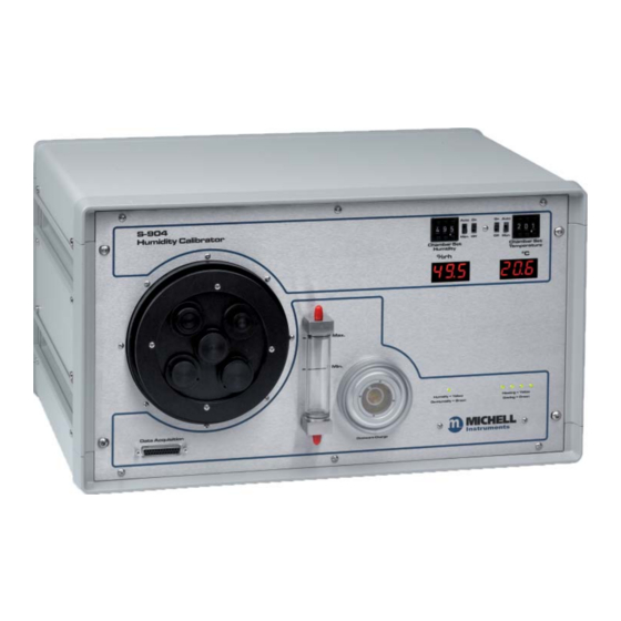
S-904
Humidity Calibrator
Data Acquisition
97209 Issue 3.1
October 2016
Auto On
4 9 5
Man. Off
Chamber Set
Humidity
%rh
Max.
Min.
Humidity = Yellow
De-Humidify - Green
Desiccant Charge
On Auto
2 0 6
Off Man.
Chamber Set
Temperature
°C
Heating = Yellow
Cooling = Green
Advertisement
Table of Contents

Related Manuals for Michell Instruments S904

Summary of Contents for Michell Instruments S904
- Page 1 S904 and S904D Humidity & Temperature Calibrator User’s Manual S-904 Auto On On Auto 4 9 5 2 0 6 Humidity Calibrator Man. Off Off Man. Chamber Set Chamber Set Humidity Temperature °C Max. Min. Humidity = Yellow Heating = Yellow...
- Page 2 Please fi ll out the form(s) below for each instrument that has been purchased. Use this information when contacting Michell Instruments for service purposes. Instrument Code Serial Number Invoice Date Location of Instrument Tag No Instrument Code Serial Number Invoice Date...
- Page 3 © 2016 Michell Instruments This document is the property of Michell Instruments Ltd. and may not be copied or otherwise reproduced, communicated in any way to third parties, nor stored in any Data Processing System without the express written authorization of Michell Instruments Ltd.
-
Page 4: Table Of Contents
Manual Control of Humidity and Temperature Setting .......... 14 Typical Response Times for Various Step Changes ..........14 Maximum Humidity Levels That can be Generated by the S904 Series ....15 25 pin D-sub Connector - S904 ................16 Automatic Control of Temperature and Humidity Set Points - S904 ....... 17 3.7.1... - Page 5 S904 & S904D User’s Manual Figures Figure 1 S904 ......................2 Figure 2 S904D .......................2 Figure 3 S904 - Front View ..................3 Figure 4 S904 - Back Panel ..................4 Figure 5 S904D Front panel ..................5 Figure 6 S904D - Back Panel ..................6 Figure 7 Control Probe Installation ................7...
-
Page 6: Safety
Michell Instruments’ worldwide offi ces contact information. Calibration The internal reference probe (HT961T00) should be re-calibrated annually. The probe should be returned to the manufacturer, Michell Instruments, or one of their accredited service agents for re- calibration. Safety Conformity This product meets the essential protection requirements of the relevant EU directives. -
Page 7: Abbreviations
S904 & S904D User’s Manual Abbreviations The following abbreviations are used in this manual: °C degrees Celsius °F degrees Fahrenheit alternating current direct current maximum minimum percentage relative humidity RS232 serial data transmission standard temperature Universal Serial Bus Volts milli Ampere... -
Page 8: Warnings
S904 & S904D User’s Manual Warnings The following general warnings listed below are applicable to this instrument. They are repeated in the text in the appropriate locations. Where this hazard warning symbol appears in the following sections it is used to indicate areas where potentially hazardous operations need to be carried out. -
Page 9: Introduction
10 minutes, so a simple 3-point calibration can be carried out in under an hour. The S904 Series is easy to maintain. The desiccant changes color to indicate when it needs to be recharged and this is visible through a clear window on the front of the unit. -
Page 10: Comparison Of The S904 And S904D
S904 & S904D User’s Manual INTRODUCTION 1.1.1 Comparison of the S904 and S904D The S904D has the Data Acquisition connector on the rear panel, and a blanking plate fi tted to the front panel, as shown in Figure 2. The S904D also features a USB, and an RS232 port on the rear panel, for communication with the LabVIEW application software. -
Page 11: System Components
S904 & S904D User’s Manual INTRODUCTION System Components 1.2.1 S904 Front Panel S904 S-904 Auto On On Auto 3 8 0 2 3 0 Humidity Calibrator Man. Off Off Man. Chamber Set Chamber Set Humidity Temperature °C Max. Min. Humidity = Yellow... -
Page 12: Figure 4 S904 - Back Panel
Figure 4 S904 - Back Panel Ventilation fans Electrical mains connector, on/off switch and power input fuse Accessories The S904 humidity and temperature generator is delivered with the following standard accessories: • Bottle of distilled water • Desiccant cell fi lled with silica gel •... -
Page 13: S904D
S904 & S904D User’s Manual INTRODUCTION 1.2.2 S904D Front Panel S904D S-904 Auto On On Auto 3 8 0 2 3 0 Humidity Calibrator Man. Off Off Man. Chamber Set Chamber Set Humidity Temperature °C Max. Min. Humidity = Yellow... -
Page 14: Figure 6 S904D - Back Panel
S904 & S904D User’s Manual INTRODUCTION Back Panel S904D S904D - Back Panel Figure 6 Ventilation fans Electrical mains connector, on/off switch and power input fuse Data acquisition connector USB connection RS232 connection Accessories The S904D humidity and temperature generator is delivered with the following standard accessories: •... -
Page 15: Installation
Before using the S904 Series, make sure that Sections 2.1, 2.2 and 2.4 are read thoroughly. The S904 Series’ enclosure is designed for bench top mounting in a laboratory type environment. It must be positioned in a clean and level location with suffi cient clearance at the rear of the enclosure for adequate ventilation. -
Page 16: Figure 8 Location Of Control Probe Inside The Climate Chamber
S904 & S904D User’s Manual INSTALLATION Control Probe Connector TOP VIEW + SUPPLY (8 - 35 VDC) OUTPUT RH OUTPUT TEMP BOTTOM VIEW Figure 8 Location of Control Probe Inside the Climate Chamber 97209 Issue 3.1, October 2016... -
Page 17: Filling The Water Reservoir
S904 & S904D User’s Manual INSTALLATION Filling the Water Reservoir Before operation the water reservoir located on the front panel must be fi lled with distilled water (supplied with the instrument). Do not use tap water or demineralized water! Figure 9 Filling the Water Reservoir Use the bottle supplied to fi... -
Page 18: Draining The Water Reservoir
S904 & S904D User’s Manual INSTALLATION Draining the Water Reservoir Drain the water reservoir before transporting, or if the system is accidentally overfi lled. To empty the water reservoir: Remove the red caps from the bottom and top of the water reservoir. -
Page 19: Desiccant
S904 & S904D User’s Manual INSTALLATION Desiccant The S904 Series has a container fi lled with a desiccant which is used to dry the air. Figure 11 Desiccant Replacement The desiccant container can be accessed by following these steps: Remove the clear plastic screw cap on the front panel. -
Page 20: Power Supply
S904 & S904D User’s Manual INSTALLATION Power Supply A single mains power supply between 100 to 240 V AC is required to operate the unit. The power supply connection is a 3-pin IEC plug located on the rear panel of the instrument. -
Page 21: Operation
S904 & S904D User’s Manual OPERATION OPERATION Preparation 3.1.1 Installing Relative Humidity Instruments for Calibration Relative humidity probes can easily be installed into the humidity chamber through the ports in the door. The amount and size of the ports are supplied per customer specifi... -
Page 22: Start-Up
S904 & S904D User’s Manual OPERATION Start-Up After installing the instruments for calibration, switch on the S904 Series by using the switch on the rear panel of the instrument. ON/OFF Manual Control of Humidity and Temperature Setting The desired percentage of relative humidity and temperature (in °C) can be manually... -
Page 23: Maximum Humidity Levels That Can Be Generated By The S904 Series
S904 & S904D User’s Manual OPERATION The S904 Series can also be used with relative humidity generation only or with temperature generation only. For example: If the calibration of the instruments is complete and new instruments need to be inserted, both switches can be set to . -
Page 24: 25 Pin D-Sub Connector - S904
S904 & S904D User’s Manual OPERATION 25 pin D-sub Connector - S904 These two connectors provide % RH and temperature outputs from the chamber control probe. 15 free pins wired from the internal chamber connector to the front panel connector can be used for any purpose. -
Page 25: Automatic Control Of Temperature And Humidity Set Points - S904
To enable external setpoint control, connect +5 V to this pin with respect to ground. Automatic Control of Temperature and Humidity Set Points - S904 These instructions do not apply to the S904D. To enable the S904 set points to be controlled using a voltage input: Auto On On Auto... -
Page 26: 25 Pin D-Sub Connector - Rear Panel And Inside Chamber - S904D
S904 & S904D User’s Manual OPERATION 3.7.1 25 pin D-sub Connector - Rear Panel and Inside Chamber - S904D These two connectors provide 6 channels for data acquisition, a +14.5 V supply, ground connection and 9 free pins wired from the internal chamber connector to the rear panel connector that can be used for any purpose. -
Page 27: S904D Example Wiring Diagrams
S904 & S904D User’s Manual OPERATION 14.5 V Supply - PIN 25 This pin is connected to the internal power supply of the S904D and can be used to provide power to probes inside the chamber. NOTE: For safety purposes the power supply is fi tted with a thermal cut-out that is connected to the rear panel 25-pin connector only. -
Page 28: Figure 22 S904D Wiring Diagram Example 2
S904 & S904D User’s Manual OPERATION The following diagram shows how to connect three % RH probes using the 25-pin D-sub connector on the rear panel of the S904D, and powering the probes using the internal S904D power supply while logging their % RH and temperature outputs. -
Page 29: Application Software - S904D
S904 & S904D User’s Manual APPLICATION SOFTWARE APPLICATION SOFTWARE - S904D NOTE: See on how to install the S904D software. Installation Guide S904D Connecting and Starting the S904D Software Connect the S904D to the computer, by using the USB cable or through the RS232 port. -
Page 30: Labview ® Software Menu Structure
S904 & S904D User’s Manual APPLICATION SOFTWARE Click on to confi rm. Once the connection is established, the green light will come on. interface LabVIEW Software Menu Structure ® This section covers the navigation of the LabVIEW software. ® 4.2.1 Command - File 97209 Issue 3.1, October 2016... -
Page 31: Command - Settings
S904 & S904D User’s Manual APPLICATION SOFTWARE Page Setup A print header containing the name, date and page number can be added to the fi le for printing. The print margins can also be changed. Print Window If required for reporting purposes a... -
Page 32: Command - Tools
S904 & S904D User’s Manual APPLICATION SOFTWARE Retrieve Control Settings To load a (previously) saved setpoint settings fi le click on Retrieve Control Settings Save Control Settings All setpoint settings can be saved by clicking on . The fi le can Save Control Settings then be saved under a unique name. - Page 33 S904 & S904D User’s Manual APPLICATION SOFTWARE Logging During the different conditions generated in the chamber, all data can be saved to the log fi le. A maximum of 6 channels can be logged, plus the internal reference probe with temperature and relative humidity.
- Page 34 S904 & S904D User’s Manual APPLICATION SOFTWARE Project name Type the name of the project. File header text Text written here will appear above the report. The following data can also be logged : Date stamp The date from the PC where the log fi le is saved to will be used.
- Page 35 S904 & S904D User’s Manual APPLICATION SOFTWARE Default / Clear Labels Sets / clears the channel names to their defaults: Chan3, Chan4, Chan5, Chan6, Chan7, Chan8. NOTE: Channels 1 and 2 are dedicated channels and cannot be changed. Save Log Settings All log settings can be saved by clicking on .
- Page 36 S904 & S904D User’s Manual APPLICATION SOFTWARE button will now be enabled. Log to File Log to File Type the name for the log fi le. The name and path will be visible at the bottom of the log settings window.
- Page 37 S904 & S904D User’s Manual APPLICATION SOFTWARE The green light will come on. Log file Monitor Ones the program is running it is possible to open a new window: Process Monitor This window will display the status of humidity, temperature, setpoints and time.
-
Page 38: Command - Help
S904 & S904D User’s Manual APPLICATION SOFTWARE Graph This option opens a new window showing the logged data in a graph. 4.2.4 Command – Help About Click on to fi nd the software version number. About USB Interface driver Click on the USB Interface driver to install the CP210x USB to UART Bridge Driver (see S904D Controller Installation Guide). -
Page 39: Labview ® Software User Interface
S904 & S904D User’s Manual APPLICATION SOFTWARE LabVIEW Software User Interface ® The user interface consists of several sections. Up to 32 set points can be programmed by the user. Only 10 are visible - use the scroll-bar to show the other 22. - Page 40 S904 & S904D User’s Manual APPLICATION SOFTWARE Duration Duration represents the time that the control reserves for one pair of setpoints (RH +T). This time includes the Ramp time. The control will proceed with the next program step if this time has elapsed. This is also true when a certain setpoint is not achieved.
- Page 41 S904 & S904D User’s Manual APPLICATION SOFTWARE Progress A green light will show the actual setpoint. Start Press the start button to start the program and / or logging. Michell Instruments...
- Page 42 S904 & S904D User’s Manual APPLICATION SOFTWARE Click on to start the process. The process starts and the green light will come on. The program runs all setpoints sequentially. After the last setpoint the program stops. Click on to fi nish.
- Page 43 S904 & S904D User’s Manual APPLICATION SOFTWARE Log fi le The log fi le is a comma separated fi le. When it is loaded into Excel it will look like this: Actual Values Michell Instruments...
- Page 44 S904 & S904D User’s Manual APPLICATION SOFTWARE The overview with the momentary values shows: Reading The reading of the internal reference probe, temperature and relative humidity. Setpoint The actual setpoint. Time elapsed / Time to end The time elapsed so far and the estimated time to the end of all steps.
- Page 45 S904 & S904D User’s Manual APPLICATION SOFTWARE To avoid a long period of time between switching off the S904D and the end of the S904D control program there is a button. default after completion Activation of this button creates an additional setpoint of ±20°C and 50%RH after the program is fi...
- Page 46 S904 & S904D User’s Manual APPLICATION SOFTWARE Action needed : Set temperature setpoint to 20.0°C, set humidity setpoint to 50%RH. Set slope for temperature to 99.9 (the S904D will go to the T-setpoint as fast as possible). Set slope for humidity to 999.9 (the S904D will go to the RH-setpoint as fast as possible).
- Page 47 S904 & S904D User’s Manual APPLICATION SOFTWARE Michell Instruments...
-
Page 48: Maintenance
S904 & S904D User’s Manual MAINTENANCE MAINTENANCE Troubleshooting Problem Possible Solution No drying Change desiccant Water in chamber; dry the chamber No humidifying Water level too low No drying and humidifying Switch 1 is off (see below) No heating or cooling... - Page 49 S904 & S904D User’s Manual APPENDIX A Appendix A Technical Specifi cations Michell Instruments...
-
Page 50: Appendix A Technical Specifi Cations
S904 & S904D User’s Manual APPENDIX A Appendix A Technical Specifi cations Humidity Generator Range 10 - 90% RH ≤ ±1% RH (10 - 70% RH) Accuracy Control Element ≤ ±1.5% RH (70 - 90% RH) Stability ±0.2% RH (20 - 80% RH) Temperature +10 to +50°C (+50 to +122°F) - Page 51 S904 & S904D User’s Manual APPENDIX B Appendix B EU Declaration Michell Instruments...
-
Page 52: Appendix Beu Declaration
– EMC requirements –Class B (emissions) and Industrial +A1:1998 Locations (immunity). +A2:2001 EN61010-1:2010 Safety Requirements for Electrical Equipment for Measurement, Control, and Laboratory Use - Part 1: General Requirements Peter Haakma, Managing Director Michell Instruments Benelux B.V. Date of Issue: October 2016 97209 Issue 3.1, October 2016... - Page 53 S904 & S904D User’s Manual APPENDIX C Appendix C Quality, Recycling & Warranty Information Michell Instruments...
-
Page 54: Appendix C Quality, Recycling & Warranty Information
The directives’ aim is to reduce the impact that electronic devices have on the environment. Michell Instruments is in full compliance with the WEEE Directive and is registered with an approved recycler (Registration No. WEE/JB0235YW) and treats the requirement of the directive and the protection of the environment with the utmost importance. -
Page 55: Rohs2 Compliance
Equipment product sold into the EU market place as 22nd July 2017. However, the careful design policy of all Michell Instruments’ products continues to attain compliance in the shortest practical timescales and strives to ensure that less than 0.1% of total mass per product, of all non-compliant materials, appear within them. -
Page 56: Reach Compliance
Our continued review of the SVHC Candidate List and latest additions is to ensure we remain compliant. Michell Instruments maintains a hazardous material register in which MSDS data sheets are collated, and we will check that our suppliers will comply to REACH requirements for all materials and substances we use in the processes of our manufacturing. -
Page 57: Calibration Facilities
S904 & S904D User’s Manual APPENDIX C Calibration Facilities Michell Instruments’ calibration facilities are among the most sophisticated in the world and have been recognized for their excellence. Traceability to the National Physical Laboratory (NPL) UK is achieved through our UKAS Accreditation (Number 0179). - Page 58 S904 & S904D User’s Manual APPENDIX D Appendix D Return Document & Decontamination Declaration 97209 Issue 3.1, October 2016...
-
Page 59: Appendix D Return Document & Decontamination Declaration
Has the equipment been cleaned and decontaminated? NOT NECESSARY Michell Instruments will not accept instruments that have been exposed to toxins, radio-activity or bio-hazardous Work will not be carried out on any unit that does not have a completed decontamination declaration. - Page 60 http://www.michell.com...
Need help?
Do you have a question about the S904 and is the answer not in the manual?
Questions and answers