Advertisement
Quick Links
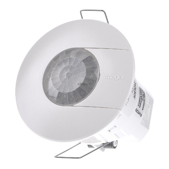
Annexe de paramétrage pour
e
a
détecteurs de présence 360°
Appendix : settings instructions
i
z
for presence detectors 360°
TCC520E
tebis
TP
RF
Montage au plafond
Ceiling mounting
3
t
10 < t < 28 mm
2
Couvercle de
protection
Protective cover
1
Serre-câble
Cable clamp
1
1
Bus
230V~
30 V
Montage en saillie (avec l'accessoire EEK005)
Surface mounting (with accessory EEK005)
Plafond
Ceiling
EEK005
2
1
Hager 08.19
hager 09/17
Raccordements / Connection
L'
L
230 V
L
N
FR
Montage au plafond
1. Percer un trou de diamètre 60-63mm avec
une scie cloche.
2. Fixer le détecteur en poussant sur les
2 ressorts vers le haut puis l'insérer dans
le trou précédemment découpé.
3. Câbler le détecteur conformément au
schéma de raccordement préconisé.
4. Clipser le capot de protection sur le bornier
et visser le serre-câble.
5. Régler les potentiomètres selon les valeurs
désirées.
Remarque :
l'épaisseur du support plafond (t) doit être
comprise entre 10 et 28mm.
Montage en saillie
(avec l'accessoire EEK005)
1.Vissez l'accessoire sur la boite
d'encastrement.
2. Enlevez le couvercle de protection et
les ressorts de fixation.
3. Câblez le détecteur selon le schéma de
cablage recommandé.
4. Poussez et tournez le détecteur pour le
verrouiller à l'intérieur de
l'accessoire.
5. Ouvrez le tiroir pour régler les valeurs
souhaitées à l'aide des potentiomètres.
Mise en oeuvre
Afin d'obtenir des conditions optimales de
détection, il est souhaitable de respecter les
préconisations suivantes :
- Hauteur d'installation recommandée :
2.5 m ¬ 3.5 m
- Dans les bureaux, le détecteur doit être
installé près du poste de travail.
- Si plusieurs détecteurs sont utilisés, les
zones de détections doivent se chevaucher.
- Eviter les perturbations dues à l'environne-
ment (sources de chaleur, cloisons, plantes
vertes, aération, ...).
Que faire si ?
• Enclenchement intempestif du point
d'éclairage :
Vérifier que le détecteur n'est pas exposé
directement à une source de chaleur, à une
source lumineuse, au dessus d'une grille
d'aération...
• La portée du détecteur est trop faible:
Vérifier si la hauteur d'installation et
l'emplacement du détecteur sont optimaux.
6LE002255C
2
6LE002255B
2
bus
Bouton poussoir communicant
Remote push button
Remote push button
Remote load
Comment éliminer ce produit (déchets d'équipements
électriques et électroniques).
(Applicable dans les pays de l'Union Européenne et aux
autres pays européens disposant de systèmes de collecte
sélective).
Ce symbole sur le produit ou sa documentation indique qu'il ne doit
pas être éliminé en fin de vie avec les autres déchets ménagers.
L'élimination incontrôlée des déchets pouvant porter préjudice à l'en-
vironnement ou à la santé humaine, veuillez le séparer des autres
types de déchets et le recycler de façon responsable. Vous favorise-
rez ainsi la réutilisation durable des ressources matérielles.
Les particuliers sont invités à contacter le distributeur leur ayant vendu
le produit ou à se renseigner auprès de leur mairie pour savoir où et
comment ils peuvent se débarrasser de ce produit afin qu'il soit recy-
clé en respectant l'environnement.
Les entreprises sont invitées à contacter leurs fournisseurs et à
consulter les conditions de leur contrat de vente. Ce produit ne doit
pas être éliminé avec les autres déchets commerciaux.
å
Utilisable partout en Europe
et en Suisse
EN
Ceiling mounting
1. Cut out a 60-63mm diameter hole using a hole
saw.
2. Fix the detector by pushing both springs upward
then insert them into the hole.
3. Wire the detector according to the
recommended connection diagram.
4. Mount the protective cover over the
terminals and screw the cable clamp.
5. Set potentiometers according to the
desired values.
Note :
The thickness of the support ceiling (t) must be
within 10 to 28mm range.
Type de charges / Lighting loads
Incandescentes, Halogène 230 V
Incandescent, Halogen 230 V
Halogène TBT via transformateur ferromagnétique ou
électronique
Halogen VLV via ferromagnetic or electronic transformer
Fluocompactes via ballast électronique
Fluocompact with electronic ballasts
Tubes fluorescents compensés en parallèle
Parallel compensated fluorescent tubes
Fluorescentes via ballast électronique
Fluorescent via electronic ballasts
S
urface mounting
(with accessory EEK005)
1. Screw the accessory on the flush mounting
box.
2. Remove the protective cover and the
springs from the detector.
3. Wire the detector according to the
recommended connection diagram.
4. Push and turn the detector to lock it into
the accessory.
5. Open the slider to set the potentiometers
according to the desired values.
Implementation requirements
Requirements for optimal detection:
- Recommended installation distance from
ground : 2.5 m ¬ 3.5 m
- In offices, the detector must be installed
above the workstation.
- When using several detectors, detection
areas shall overlap.
- Keep away from environmental disturbances
(heat sources, partitions, houseplants,
ventilation,...).
Trouble shooting
• False switching of lighting point :
Check that the detector is not exposed directly
to a heat source or a lighting source, or is not
placed above a ventilation grid...
• The range of the detector is too short :
Check whether the distance of the device
from the ground is sufficient and its location
is optimal.
Correct Disposal of This product (Waste Electrical &
Electronic Equipment).
(Applicable in the European Union and other
European countries with separate collection sys-
tems).
This marking shown on the product or its literature indicates
that it hould not be disposed with other household wasted at
the end of its working life. To prevent possible harm to the envi-
ronment or human health from uncontrolled waste disposal,
please separate this from other types of wastes and recycle it
responsibly to promote the sustainable reuse of material
resources.
Household users should contact either the retailer where they
purchased this product, or their local government office, for
details of where and how they can take this item for environ-
mentally safe recycling.
Business users should contact their supplier and check the
terms and conditions of the purchase contract. This product
should not be mixed with other commercial wastes of disposal.
å
Usable in all Europe
and in Switzerland
L'
16A AC1
2300 W
1500 W
23 x 23 W
1000 W
1000 W
Hager 08.19
6LE002255C
hager 09/17
6LE002255B
Advertisement

Related Manuals for hager TCC520E


Summary of Contents for hager TCC520E
- Page 1 5. Open the slider to set the potentiometers according to the desired values. Bouton poussoir communicant Remote push button Remote push button Remote load TCC520E 230 V Implementation requirements Requirements for optimal detection: - Recommended installation distance from tebis ground : 2.5 m ¬ 3.5 m...
- Page 2 Verwendbar in ganz Europa und in der Schweiz Hager 08.19 6LE002255C Hager Controls S.A.S., 33 rue Saint-Nicolas, B.P. 10140, 67703 SAVERNE CEDEX, France - www.hager.com Hager Controls S.A.S., 33 rue Saint-Nicolas, B.P. 10140, 67703 SAVERNE CEDEX, France - www.hager.com Hager 08.19 hager 09/17...
Need help?
Do you have a question about the TCC520E and is the answer not in the manual?
Questions and answers