Table of Contents
Advertisement
Quick Links
Advertisement
Table of Contents

Related Manuals for Sondermann MAGSON MA Series

Summary of Contents for Sondermann MAGSON MA Series
- Page 1 MAGSON magnetically coupled centrifugal pumps MA types 4 to 7 Operating Manual...
-
Page 2: Table Of Contents
Table of contents Declaration of conformity ............4 Basic information ..............6 2.1 Notes on the operating manual ..............6 2.2 Validity of data ..................6 2.3 Purpose ....................6 2.4 Use to the intended purpose ..............6 2.5 Anticipated misuse ..................7 2.6 Limits of use .................... - Page 3 6.3.5 Electrical connection ..............17 6.3.6 Controlling the direction of rotation ..........18 Putting into operation ............. 19 7.1 Safety precautions .................. 19 7.2 Preparatory work ..................19 7.3 Putting into operation ................19 7.4 Possible malfunction when putting the pump into operation ...... 20 Shut-down procedure .............
-
Page 4: Declaration Of Conformity
Declaration of conformity... - Page 5 MAGSON centrifugal pumps Issue 2019-01 Declaration of conformity...
-
Page 6: Basic Information
2. Basic information Notes on the operating manual This operating manual has been prepared to meet all product-specific and user-related requirements of the law and of all relevant regulations and rules, technical standards, directives and agreements. The manual includes important information on the functioning of MAGSON magnetically coupled centrifugal pumps and how to use, install, service and dispose of them. -
Page 7: Anticipated Misuse
The pump must only be used to the intended purpose specified by this operating manual. Inappropriate operation or insufficient service and maintenance will cancel the right to all warranty claims. Contact details SONDERMANN Pumpen + Filter GmbH & Co. KG August-Horch-Strasse 2 51149 Cologne (Porz), Germany... -
Page 8: Safety
Safety Standards and directives Name Contents 2006/42/EG Directive 2006/42/EC of the European Parliament and of the Council of 17 May 2006 on machinery, and amending Directive 95/16/ECG (recast) (1) 2014/30/EU Directive 2014/30/EU of the European Parliament and of the Council of 26 February 2014 on the harmonisation of the laws of the Member States relating to electromagnetic compatibility (recast) Table 1: European Directives... -
Page 9: Depiction Of Safety Instructions
Depiction of safety instructions All safety instructions of this document are marked with symbols designed on the basis of the SAFE principle. Each of them describes the kind and source of danger, possible consequences and information on how to avert them. DANGER The symbol warns you of a potential accident resulting from ignoring safety or other instructions. -
Page 10: Technical Information
4. Technical Information General description MAGSON magnetically coupled centrifugal pumps are non-self priming centrifugal pumps made of plastic and built in horizontal single-stage monoblock design. A magnetic coupling connects the pump to the motor and transmits the power of the motor to the impeller. - Page 11 Overview of available materials being in contact with fluid: Component Symbol Material Temperature Polypropylene 0 to 70°C ETFE Ethylene tetrafluoride ethylene -20 to +100°C All components in contact PTFE Polytetrafluoroethylene -20 to +100°C with fluid Carbon fiber reinforced CFR-PTFE -20 to +100°C polytetrafluoroethylene Polyphenylene sulphide -20 to +100°C...
-
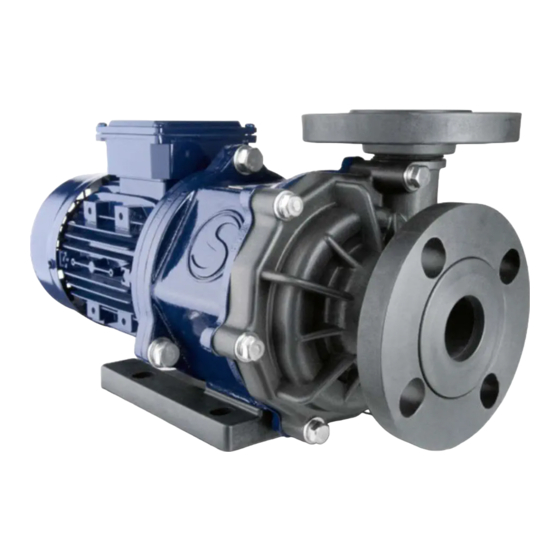
Page 12: Structure Of Magson Ma Pumps
Structure of MAGSON MA pumps Fig. 1: Structure of an MA pump of type 4 Slip-on flange Pump housing Impeller magnet O-ring of housing Rear casing Starting ring of rear casing Mounting flange Lantern Driving magnet 10 Adapter plate (types 4 and 6 only) 11 Motor 12 Base plate... -
Page 13: Transport And Temporary Storage
Overview of MAGSON MA pump types Suction Discharge Size non self priming port port 7/70 Type 2 8/80 15/40 G 1 ½“ G 1 ½“ Type 3 10/100 13/120 8/160 10/180 Type 4 12/190 14/220 DN40 10/240 13/260 Type 5 DN40 15/280 18/320... -
Page 14: Installation
6. Installation Safety precautions WARNING Danger of getting jammed or bruised during installation of the pump If necessary, use lifting and holding devices suitable to the size and weight of the pump. Make sure that all installation work is done by competent and qualified personnel only. WARNING Danger of being hit by falling components If necessary, use lifting and holding devices suitable to the size and weight of the pump. -
Page 15: Suction Line
6.3.2 Suction line ATTENTION Risk of damaging the pump by cavitation When installing the suction line, make sure to meet the NSPH value given in the æ Appendix page 30 foll.. If the NPSH falls below this value, there will be cavitation resulting in running noise, drumming and vibration of the pump. -
Page 16: Flange Or Threaded Connections
6.3.4 Flange or threaded connections MAGSON MA pumps of types 4 to 6 are equipped with slip-on flanges as standard features. The rotating flange allows you to easily connect the pump without considering the angular position of the mating flange. Do not use hard material to seal the flange but appropriate elastomer seals. -
Page 17: Electrical Connection
3. Screw the threaded adapter to the pump housing using the strap wrench. Make sure that the O-ring fits exactly into the groove of the inner thread. 6.3.5 Electrical connection NOTE Qualified personnel only are allowed to connect the pump to the electrical mains. All electrical connections and the installation of additional protection devices has to be done in accordance with the regulations of your local power supplier and the VDE Association of German Electrical Engineers. -
Page 18: Controlling The Direction Of Rotation
6.3.6 Controlling the direction of rotation ATTENTION Dry-running will damage the pump Do not check the direction of rotation when there is no fluid in the pump! 1. Mind the direction of rotation indicated by an arrow on the pump. Before verifying it after the installation, fill the pump housing and suction line with water or fluid. -
Page 19: Putting Into Operation
Putting into operation Safety precautions WARNING Danger of breaking during operation Regularly check the pump for damages. If there is a damage, the pump must not be operated! Replace wearing parts at regular intervals. Do not operate the pump to other than the intended purpose. WARNING Risk of electrical hazards when touching parts carrying voltage by fault Fasten all loose connections. -
Page 20: Possible Malfunction When Putting The Pump Into Operation
WARNING Hazard of pressure Use a manometer at the discharge line to check the system pressure and prevent it from going beyond its limit specified in the technical data sheet (see Appendix). If the system pressure is too high, the rear casing may burst releasing fluid. When pressure testing the piping, take into account the maximum system pressure, but do not test the pump as well, if possible. -
Page 21: Shut-Down Procedure
8. Shut-down procedure 1. Switch off the motor. 2. Close the shut-off valves. 3. When some fluid remains within the pump, secure the shut-off valves to prevent an accidental opening. 4. In case of crystallizing fluids, heat both the pump and the piping. Protect freezing fluids against frost. -
Page 22: Service And Maintenance
9. Service and maintenance Safety precautions WARNING Risk of electrical hazards when touching parts carrying voltage by fault Only qualified and authorized personnel are allowed to work on motors at a standstill. The motors have to be disconnected and secured against any accidental start. Strictly follow the instructions of the motor manufacturer. -
Page 23: Preventive Maintenance
Preventive maintenance 9.3.1 Overall pump Check the pump at regular intervals for 1. vibrations or unusual noise, 2. a minimum volume flow of at least 5% of the maximum volume flow, 3. changes in normal operating conditions, overheating or dry-running, 4. -
Page 24: Motor
Replace the O-ring as soon as the elastomer shows signs of chemical attack, fissures or loss of elasticity. NOTE All spare parts are available at Sondermann Pumpen + Filter GmbH & Co. KG. See the Appendix for the spare parts lists. When delivering dirty, muddy or crystallizsing fluids, you should check and clean the pump at shorter intervals. -
Page 25: Dismantling And Replacing The Motor
Dismantling and replacing the motor The back pull-out design allows you to replace the entire drive unit without dismounting the pump. So neither the pump nor the piping have to be drained. Just loosen the 4 motor screws and pull the motor off the pump. -
Page 26: Disassembling The Pump Head
Disassembling the pump head Press out the sleeve bearing of the impeller magnet and replace it. Press out the shaft mounting of the front housing and replace it (Types 4-6). Use appropriate tools to press out the components. If in doubt, ask the manufacturer to replace them. - Page 27 Screw the lantern to the motor flange or Screw the mounting flange to the lantern adapter plate (using 3 screws for type 4, 4 making sure that the driving magnet is screws for type 6). freely rotating. The “S“ mark should be at the bottom.
-
Page 28: Troubleshooting
10. Troubleshooting Malfunction Cause Elimination The pump does not start No voltage. Check the voltage. when being switched on. The impeller jams. Check both the impeller and the fan blade of the motor for easy movement. The magnetic coupling The relative density Reduce the delivery rate;... - Page 29 Malfunction Cause Elimination The delivery rate is too Pump losses are less Reduce the flow rate of the high. significant than discharge line. presumed. Reduce the impeller diameter. Use a frequency converter to adjust the motor speed. Unusual mechanical Damaged bearing of the Take the motor off the pump running noise.
-
Page 30: Appendix
Appendix Technical data of MA pumps of type 4 / 4H Table 5: Technical data of MA pumps of type 4 / 4H Fig.. 2: Technical drawing of an MA pump of type 4 / 4H... - Page 31 Fig. 3: Characteristic curves of MA pumps of type 4 / 4H, measured with water of 20°C MAGSON centrifugal pumps Issue 1| 2019-01 Appendix...
- Page 32 Technical data of MA pumps of type 5 / 5H Table 6: Technical data of MA pumps of type 5 / 5H Fig. 4: Technical drawing of an MA pump of type 5 / 5H...
- Page 33 Fig. 5: Characteristic curves of MA pumps of type 5, measured with water of 20°C MAGSON centrifugal pumps Issue 1| 2019-01 Appendix...
- Page 34 Technical data of MA pumps of type 6 / 6H Table 7: Technical data of MA pumps of type 6 / 6H Fig.. 6: Technical drawing of an MA pump of type 6 / 6H...
- Page 35 Fig. 7: Characteristic curves of MA pumps of type 6 / 6H, measured with water of 20°C MAGSON centrifugal pumps Issue 1| 2019-01 Appendix...
- Page 36 D)Technical data of MA pumps of type 7 Table 8: Technical data of MA pumps of type 7 Fig.. 8: Technical drawing of an MA pump of type 7...
- Page 37 Fig. 9: Characteristic curves of MA pumps of type 6 / 6H, measured with water of 20°C MAGSON centrifugal pumps Issue 1| 2019-01 Appendix...
- Page 38 Exploded view of an MA pump of type 4 / 4H...
- Page 39 Spare parts list for MA pumps of type 4 / 4H Part no. Quantity Article no. Name Material Pump housing see technical data sheet Mounting flange grey cast iron Rear casing see technical data sheet Centering axis aluminium oxide ceramic 99.7% 230.847 Impeller magnet see technical data...
- Page 40 Exploded view of an MA pump of type 5 / 5H...
- Page 41 Spare parts list for MA pumps of type 5 / 5H Part no. Quantity Article no. Name Material Pump housing see technical data sheet Mounting flange grey cast iron Rear casing see technical data sheet Centering axis aluminium oxide ceramic 99.7% 230.847 Impeller magnet see technical data...
- Page 42 G)Exploded view of an MA pump of type 6 / 6H (1.5-2.2kW motor)
- Page 43 Spare parts list for MA pumps of type 6 with 1.5 to 2.2kW motor Part no. Quantity Article no. Name Material Pump housing see technical data sheet Mounting flange grey cast iron Rear casing see technical data sheet Centering axis aluminium oxide ceramic 99.7% 230.847...
- Page 44 H)Exploded view of an MA pump of type 6 with 3 to 4kW motor...
- Page 45 Spare parts list for MA pumps of type 6 with 3 to 4kW motor Part no. Quantity Article no. Name Material Pump housing see technical data sheet Mounting flange grey cast iron Rear casing see technical data sheet Centering axis aluminium oxide ceramic 99.7% 230.847...
- Page 46 Exploded view of an MA pump of type 7...
- Page 47 Spare parts list for MA pumps of type 7 Part no. Quantity Article no. Name Material Pump housing see technical data sheet Mounting flange grey cast iron Rear casing see technical data sheet Centering axis aluminium oxide ceramic 99.7% 230.847 Impeller magnet see technical data sheet...
- Page 48 Safety instructions for electric motors...
- Page 49 Notwithstanding the receipt of this declaration, we reserve the right to reject its repair for other reasons. No SONDERMANN product or component of them will be accepted for service or repair unless the declaration of decontamination is enclosed! Apart from that, we do NOT accept any pump that has been operated with radioactive substances.
- Page 50 Declaration of Decontamination The undersigned herewith declare that the following pump and its accessories are harmless and ask you to service and/or repair it or them. Type: ..............................................Serial number: ........................Date of delivery: ........................Kind of problem: ..............................................
- Page 51 MAGSON centrifugal pumps Issue 1| 2019-01 Appendix...
- Page 52 This operating manual is protected by copyright and must not be copied nor transmitted or used in any form or by any means in full or in parts, unless explicitly authorized in writing by SONDERMANN Pumpen + Filter GmbH & Co. KG.
Need help?
Do you have a question about the MAGSON MA Series and is the answer not in the manual?
Questions and answers