Table of Contents
Advertisement
Quick Links
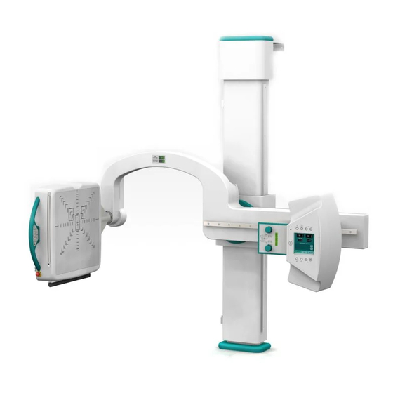
Ultra U-arm
Installation Guide
Table of Contents
Unpacking Guide pg.2
Panel System Parts pg.24
Stand Installation pg. 27
Generator Installation pg. 32
Panel Interface Wiring pg. 34
Generator Auto Calibration pg. 40
Stand Calibration pg. 42
Panel Setup and Calibration pg. 45
AEC Calibration pg. 49
Anti Crushing Verification pg. 50
J4 missing wiring pg. 50
Checks to be completed prior to Applications
arrival pg. 52
VZ0022UG201509-2.0
Customer Support
Ultra Installation Guide v2.0 1
1.800.366.5343 -
support@viztek.net
Advertisement
Table of Contents

Related Manuals for Viztek Ultra U-arm


Summary of Contents for Viztek Ultra U-arm
-
Page 1: Table Of Contents
Ultra Installation Guide v2.0 1 Ultra U-arm Installation Guide Table of Contents Unpacking Guide pg.2 Panel System Parts pg.24 Stand Installation pg. 27 Generator Installation pg. 32 Panel Interface Wiring pg. 34 Generator Jumper Configuration pg. 37 ... -
Page 2: Unpacking Guide
3. Wall Support 11. CF Card 4. X-ray Tube 12. Handle 5. Collimator 13. Grease 6. HV Cables 14. Wrench 7. Detector Assembly Support (Bucky) 15. Bags of screws, 8. Base cover 16. Column Harness Customer Support 1.800.366.5343 – support@viztek.net VZ0022UG201509-2.0... - Page 3 Ultra Installation Guide v2.0 3 U-Arm Tube Neck Wall Support Customer Support 1.800.366.5343 – support@viztek.net VZ0022UG201509-2.0...
- Page 4 Ultra Installation Guide v2.0 4 X-ray Tube Collimator Customer Support 1.800.366.5343 – support@viztek.net VZ0022UG201509-2.0...
- Page 5 Ultra Installation Guide v2.0 5 HV Cables Detector Assembly Support (Bucky) U-arm Base cover Customer Support 1.800.366.5343 – support@viztek.net VZ0022UG201509-2.0...
- Page 6 Ultra Installation Guide v2.0 6 U-arm Top Cover Tube Head Cover U-Arm Manuel Customer Support 1.800.366.5343 – support@viztek.net VZ0022UG201509-2.0...
- Page 7 Ultra Installation Guide v2.0 7 CF Card (Sedecal) , Rotation Handle, Grease, Wrench, Bags of screws, Cable Wrap, Tube Shims, &AEC Manual Customer Support 1.800.366.5343 – support@viztek.net VZ0022UG201509-2.0...
- Page 8 Second Crate packing list 1. Generator 5. Generator adapter backing 2. Generator Manuel 6. Handswitch 3. CD (software) 7. Generator cables 4. Bolts bag 8. PCI chip (on/off Board) – (not used by Viztek) Customer Support 1.800.366.5343 – support@viztek.net VZ0022UG201509-2.0...
- Page 9 Ultra Installation Guide v2.0 9 Generator Generator Manuel Customer Support 1.800.366.5343 – support@viztek.net VZ0022UG201509-2.0...
- Page 10 Ultra Installation Guide v2.0 10 CD (software) Bolts bag Generator adapter backing (attaches to stand box) Customer Support 1.800.366.5343 – support@viztek.net VZ0022UG201509-2.0...
- Page 11 Ultra Installation Guide v2.0 11 Mini Console (Handswitch) Generator Cables (Left: rotor cable Right: stand power box to generator J5 cable) Customer Support 1.800.366.5343 – support@viztek.net VZ0022UG201509-2.0...
- Page 12 Ultra Installation Guide v2.0 12 PCI chip (on/off Board) – (not used by Viztek) Customer Support 1.800.366.5343 – support@viztek.net VZ0022UG201509-2.0...
- Page 13 Ultra Installation Guide v2.0 13 Third Crate Third Crate packing list 1. Stand box Customer Support 1.800.366.5343 – support@viztek.net VZ0022UG201509-2.0...
- Page 14 3. (2) Battery Backup iv. U25 generator chip 4. Monitor Box v. Usb mouse a. Manual vi. 8gb thumb drive b. Software vii. CF Card (Viztek version) c. VGA cable viii. Warning label for d. Serial cable Handswitch 5. Grid 6. Grid frame Customer Support 1.800.366.5343 –...
- Page 15 Ultra Installation Guide v2.0 15 Crate four Toshiba panel Customer Support 1.800.366.5343 – support@viztek.net VZ0022UG201509-2.0...
- Page 16 Ultra Installation Guide v2.0 16 Toshiba software, Manual (2) Ground cables, and Generator power cord Customer Support 1.800.366.5343 – support@viztek.net VZ0022UG201509-2.0...
- Page 17 Ultra Installation Guide v2.0 17 Pc Box Tower Keyboard Customer Support 1.800.366.5343 – support@viztek.net VZ0022UG201509-2.0...
- Page 18 Ultra Installation Guide v2.0 18 Accessories and Wire Box PC Manual, Installation checklist, (2) dell software cds Viztek Mouse Pad, Usb mouse, 8gb thumb drive, CF Card (Viztek version), Warning label for Handswitch, Blue 14ft standard Ethernet cable Customer Support 1.800.366.5343 –...
- Page 19 Ultra Installation Guide v2.0 19 U24 generator chip, Black 75ft standard Ethernet cable (2) Power cords, 3ft DB9 to DB9 cable, 25ft DB9 to DB9 Cable Customer Support 1.800.366.5343 – support@viztek.net VZ0022UG201509-2.0...
- Page 20 Ultra Installation Guide v2.0 20 Toshiba Integration Board, Toshiba Integration board screws Viztek antivirus pamphlet IR Remote Customer Support 1.800.366.5343 – support@viztek.net VZ0022UG201509-2.0...
- Page 21 Ultra Installation Guide v2.0 21 (2) Battery Backup *One Battery Backup is used for the panel and the second one is used for the PC tower and the monitor. Monitor Box Monitor Manual, Software Customer Support 1.800.366.5343 – support@viztek.net VZ0022UG201509-2.0...
- Page 22 Ultra Installation Guide v2.0 22 VGA cable, Serial cable(not used for monitor) Power cord, Usb – B cord (used in place of serial cable for monitor) Grid Box Customer Support 1.800.366.5343 – support@viztek.net VZ0022UG201509-2.0...
- Page 23 Ultra Installation Guide v2.0 23 Grid frame Grid Customer Support 1.800.366.5343 – support@viztek.net VZ0022UG201509-2.0...
- Page 24 Ultra Installation Guide v2.0 24 Customer Support 1.800.366.5343 – support@viztek.net VZ0022UG201509-2.0...
-
Page 25: Panel System Parts
1 - Generator Interface Board 1 - Generator Interface Board Screw Kit 1 - Panel Mounting Screw Kit **Verify all components are present** Note: Viztek does not use the On/Off board provided with the generator. Customer Support 1.800.366.5343 – support@viztek.net... - Page 26 3. With the Column still laid on the Pallet, install the Wall Support to the top of the Column with the screws, washers and nuts provided. 4. Place the Column standing-up and position it at its final site in the room. Customer Support 1.800.366.5343 – support@viztek.net VZ0022UG201509-2.0...
- Page 27 11. Perform the corresponding connections from the Column (Main Harness) in the Control Box. 12. Remove the Positioner Control (Monitor) from the Support of the Tube Collimator Support, for that, unscrew the four fixing screws and carefully leave it resting on the Carriage Arm. Customer Support 1.800.366.5343 – support@viztek.net VZ0022UG201509-2.0...
- Page 28 19. Remove cover at back of tube support. Connect the SID cable rolled up in a bag at the upper carriage tube support. (pins 3,4, &5 on the terminal strip on back of tube support) Customer Support 1.800.366.5343 – support@viztek.net VZ0022UG201509-2.0...
- Page 29 22. Turn the Unit ON with the Switch located at the Control Box door. 23. Remove now the Safety Locking Rod from the Central Carriage. 24. Position the Swivel Arm at a comfortable position for installing the Customer Support 1.800.366.5343 – support@viztek.net VZ0022UG201509-2.0...
- Page 30 30. Install now the Detector Assembly in the Delta Support of the Swivel Arm with its fixing screws. 31. Connect the Detector cables and Assembly cables to the respective connections of the Detector. 32. Check that all controls and movements operate correctly. Customer Support 1.800.366.5343 – support@viztek.net VZ0022UG201509-2.0...
-
Page 31: Generator Installation
Pre-installation requirements, such as: • Incoming Line Power. • Main Switch and Safety Devices. • Conduits. • Space Requirements. Verify U24 chip is for Vizion (b39 or b75) (Presto is b13, b17, or b22) Customer Support 1.800.366.5343 – support@viztek.net VZ0022UG201509-2.0... - Page 32 VAC (for 3-Phase) or 480 VAC / 530 VAC (for 80 kW 3-Phase Generators). 3. Check 6T2-4 for low speed rotor only generators with Toshiba tubes is wired for 110vac/120vac. • When routing cables, take notice of cover mounting. Customer Support 1.800.366.5343 – support@viztek.net VZ0022UG201509-2.0...
-
Page 33: Panel Interface Wiring
Mini Console J5 cable from Stand power box, and the Mini Console ground from generator. A total of 3 cables need to be run through the arm of the stand. The panel power supply cable, Cat5 crossover cable, and the generator interface cable. Customer Support 1.800.366.5343 – support@viztek.net VZ0022UG201509-2.0... - Page 34 J4 in the Generator to the panel (possible an Interface Board could be provided.) If J4 is not in system go to page 32 for hard J4 In Generator To Generator wiring in the Customer Support 1.800.366.5343 – support@viztek.net VZ0022UG201509-2.0...
-
Page 35: Generator Jumper Configuration
Door Interlock • Verify SW2-3 on ATP Board is in Service Mode (page 3 of Configuration Section of the Generator Service Manual) • Verify U24 chip on ATP Board is V7R1b39 version Customer Support 1.800.366.5343 – support@viztek.net VZ0022UG201509-2.0... -
Page 36: Generator Tech Service Configuration
Figure 22 WS1 must be set as: Tube 1, Bucky 1, and which port you have selected for AEC. WS3 must be set as: Tube 1, Direct, and which port you have selected for AEC. Customer Support 1.800.366.5343 – support@viztek.net VZ0022UG201509-2.0... - Page 37 AEC Tracking AEC- J1 tracking = E08 AEC- J2 tracking = E10 AEC- J3 tracking = E24 You are now ready to calibrate the Generator Customer Support 1.800.366.5343 – support@viztek.net VZ0022UG201509-2.0...
-
Page 38: Generator Auto Calibration
Select “Yes” Figure 23 (right) Figure 2 Confirm or leave the Auto-calibration (second confirmation) by pressing the respective button (“Confirm” or “Dismiss”) on the calibration screen. Figure 24 Auto-calibration is activated when the “AutoCalibration” is shown. Figure 25 Customer Support 1.800.366.5343 – support@viztek.net VZ0022UG201509-2.0... - Page 39 . (Prep may take up to 45 seconds to start Calibration) “AutocalOK” will replace the “AutoCalibration” once the calibration is completed for the selected focal spot. Spot check generator for calibration verification. (E06 can be adjusted for proper cal) Customer Support 1.800.366.5343 – support@viztek.net VZ0022UG201509-2.0...
-
Page 40: Stand Calibration
Ultra Installation Guide v2.0 40 Stand Calibration: Hold the Positioning button for 5 seconds. Password: 2434 Customer Support 1.800.366.5343 – support@viztek.net VZ0022UG201509-2.0... - Page 41 Measure with Metric Tape from the Arm Central guide black dot to the floor Lower ramp on back of column to calibrate the detector lower to the floor and change MIN HEIGHT to match calibrated height Customer Support 1.800.366.5343 – support@viztek.net VZ0022UG201509-2.0...
- Page 42 The arm should already be at 0. Put the level on the detector yoke and level the detector to calibrate 0. If the DAC number changed within a few then -45 and 45 may not need to be adjusted. Verify calibration. Customer Support 1.800.366.5343 – support@viztek.net VZ0022UG201509-2.0...
- Page 43 For 72” run the SID out until mechanical stop switch is half an inch from the ramp. To calibrate the remote with the system, look for the “Codify” section in the stand manual. Customer Support 1.800.366.5343 – support@viztek.net VZ0022UG201509-2.0...
- Page 44 Use the following IP address IP address: 192.168.95.1 Subnet mask:255.255.255.0 Note : The Toshiba detector IP address is dependent upon physical switch on the Toshiba detector. Figure 5 IP0 : 192.168.95.30 IP1: 192.168.95.31 Figure 6 Customer Support 1.800.366.5343 – support@viztek.net VZ0022UG201509-2.0...
- Page 45 In the OpalUAI acquire screen b. Notate status of panel in top left corner Figure 4 “Config Problem” status notates panel serial number and panel type needs to be configured into the Ultra configuration. Figure 8 Customer Support 1.800.366.5343 – support@viztek.net VZ0022UG201509-2.0...
- Page 46 Select Device Configurations tab Figure 6 b. Highlight Default c. Highlight Toshiba Figure 10 a. Click Launch in The Device Configuration Page. (Figure 10) b. Verify Toshiba_4001 Driver is installed, Exit (Figure 11) Customer Support 1.800.366.5343 – support@viztek.net VZ0022UG201509-2.0...
- Page 47 Verify IP Address 192.168.95.30 (Figure 12) In Exposure Control Field, Trigger : Hardware, m. All Other settings should be default. (figure 12) n. select Apply on the Device Configuration page. o. Exit OpalUAI Figure 12 Customer Support 1.800.366.5343 – support@viztek.net VZ0022UG201509-2.0...
- Page 48 Enter User Mode 12. Set the tube at a 72 inch SID 13. Remove Grid 14. Collimate to just outside the square on bucky’s face 15. Insert 1.5 mm copper filter 16. Open C:\opal\plugins64\Toshiba\TETD_FPD_Manager64.exe Customer Support 1.800.366.5343 – support@viztek.net VZ0022UG201509-2.0...
- Page 49 • Set kvp, mAs, ma, and ms in tech service for shots. • All shots within each range must be made at same kvp and mas • After each good shot, click next. Customer Support 1.800.366.5343 – support@viztek.net VZ0022UG201509-2.0...
- Page 50 Copy Defect bin, DefectMap,Gain High, Gain Low, Fain Mid, Gain Off High,Gain Off Mid, Gain Tumb Min, Paste these into “C:\opal\plugins64\Toshiba\”2_SerialNumber”’. d. Open C:\opal\plugins64\Toshiba\”1_serial Number”\OffsetLUT e. Copy Offse A and Offset C Paste into C:\opal\plugins64\Toshiba\”2_serial Number”\OffsetLUT g. Launch Ultra. Verify with test Shots. Customer Support 1.800.366.5343 – support@viztek.net VZ0022UG201509-2.0...
-
Page 51: Aec Calibration
AEC- J2 calibration = E09 AEC- J3 calibration = E20 o AEC Tracking between 70kv and 120kv AEC- J1 tracking = E08 AEC- J2 tracking = E10 AEC- J3 tracking = E24 Customer Support 1.800.366.5343 – support@viztek.net VZ0022UG201509-2.0... -
Page 52: Anti Crushing Verification
Pin 3 - 3TS1-7 (Ground) Pin 4 - 3TS1-17 (Bucky Start 24vdc) Troubleshooting • Verify U24 Chip on ATP Board is V7R1b39, If not call Viztek to obtain proper chips. • Verify Panel NIC has an IP of 192.168.95.1 Customer Support 1.800.366.5343 –... -
Page 53: Install Guide Checklist
Tube 1 Bucky 1 IC 1 (if in J1 on the AEC Adaption Board in Generator) • WS 3 Tube 1 Direct IC 1 (if in J1 on the AEC Adaption Board in Generator) Customer Support 1.800.366.5343 – support@viztek.net VZ0022UG201509-2.0... - Page 54 Verify AEC cells are balanced (no adjustments for Claymont), cell positions are correct (left, right, and center) and density is correct. Verify generator calibrations. Verify Half value layer Verify total filtration exceeds 2.5 mm Al (tube/collimator) Customer Support 1.800.366.5343 – support@viztek.net VZ0022UG201509-2.0...
Need help?
Do you have a question about the Ultra U-arm and is the answer not in the manual?
Questions and answers