Table of Contents
Advertisement
Quick Links
Advertisement
Table of Contents

Subscribe to Our Youtube Channel
Related Manuals for NEXPEAK NX301

Summary of Contents for NEXPEAK NX301
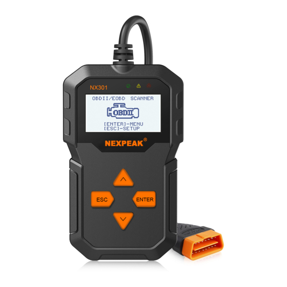
- Page 1 N 301 NEXPEAK N X 301 OBDII Scanner CAN OBDII/EOBD...
-
Page 3: Table Of Contents
Table of Contents 1.Safety Precautions and Warnings 2.General Information 2.1 About NEXPEAK NX301 2.2 Specification 2.3 Package Accessories 3.Using the Scan Tool 3.1 Tool Description 3.2 Tool Language Setup 3.3 Vehicle Coverage 4.Tool Operation 4.1 Start Diagnostics 4.1.1 Connecting to Vehicle Power 4.1.2 Connecting to Personal Computer with USB Cable... -
Page 4: Safety Precautions And Warnings
1.Safety Precautions and Warnings To prevent personal injury or damage to vehicles and/or the scan tool, read this instruction manual first and observe the following safety precautions at a minimum whenever working on a vehicle: • Always perform automotive testing in a safe environment. •... -
Page 5: General Information
NEXPEAK NX301 Features the unique patented logical navigation buttons, TFT backlit display screen and built-in speaker. The NEXPEAK NX301 is the ultimate in ease and affordability, enabling users to verify repairs, road test, check State, Emission Monitor Status and solve engine systems and drive ability problems. The car diagnostic functions of NX301is much more reliable and completely superior to other model, it support full OBDII 10 Modes diagnostics. -
Page 6: Using The Scan Tool
3.Using the Scan Tool 3.1 Tool Description NEXPEAK N X 301 OBDII Scanner 1) OBDII CONNECTOR - Connects the scan tool to the vehicle's Data Link Connector (DLC) 2) LCD DISPLAY - Displays menus and test results GREEN LED - Indicates that engine systems are running YELLOW LED- Indicates there is a possible problem. -
Page 7: Tool Language Setup
9) DOWN SCROLL BUTTON — Moves down through menu and sub menu items in menu mode. When more than one screen of data is retrieved, moves down through the current screen to next screens for additional data. It is also used as the language setup hot key when pressed. -
Page 8: Vehicle Coverage
3.3 Vehicles Coverage The scan tool is specially designed to work with all OBD II compliant vehicle's including control area network (CAN), it is required by EPA that all 1996 and newer vehicles (Cars and light trucks) sold in the united states must be OBD II compliant. -
Page 9: Tool Operation
4. Tool Operation 4.1 Start Diagnostics Before using the code reader, make sure to provide power to the code reader.The unit operates on any of the following sources: - 12-volt vehicle power - USB connection to personal computer. 4.1.1 Connecting to Vehicle Power The code reader normally powers on whenever it is connected to the data link connector (DLC). - Page 10 • Pending Codes: Pending codes are referred to as maturing codes that indicate intermittent faults. If the fault does not occur within a certain number of drive cycles (depending on vehicle), the code clears from memory. If a fault occurs a specific number of times, the code matures into a DTC and the MIL illuminates or blinks.
-
Page 11: Erase Codes
Sensor 1 Circuit High Note: If no DTCs are present, the message "No (Pending) Codes Found!" is displayed. If any manufacturer specific or enhanced codes detected, NX301 reads the correct DTC information automatically according to the VIN. 4.3 Erase Codes CAUTION: 1.To clear codes, make sure that the ignition key is switched to ON... - Page 12 A warning message comes up asking for your confirmation. Erase Codes Erase trouble codes! Are you Sure? Press ENTER button to confirm. • If the codes are cleared successfully, an "Erase Done!" confirmation message shows on the display. Erase Codes Erase Done! Press any key to con.
-
Page 13: Live Data
4.4 Live Data 4.4.1 View Data The View Data function allows viewing of live or real time PID data of vehicle's computer module(S). 1) To view live data, use UP/DOWN scroll button to select Live Data from Diagnostic Menu and press ENTER button. Diagnostic Menu 3/11 Read Codes... - Page 14 Viewing Complete Data Set 4) To view complete set of data, use UP/DOWN scroll button to select Complete Data Set from View Data menu and press ENTER button. 5) View live PIDs on the screen. Use UP/DOWN scroll button for more PIDs if an UP or DOWN arrow appears on the screen.
-
Page 15: Record Data
4.4.2 Record Data The Record Data function allows recording vehicle modules' Parameter Identification (FID) data to help diagnose intermittent vehicle problems. A recording includes 5 frames of live data before trigger event and several frames after trigger event. There are two trigger modes used to record data: A. -
Page 16: Playback Data
4.4.3 Playback Data The Playback Data function allows viewing of previously stored PID data. 1) To playback recorded data, use UP/DOWN scroll button to select Playback Data from Live Data menu and press RNTER button. Live Data View Data Record Data Playback Data You are also allowed to playback recorded data immediately after recording. -
Page 17: View Freeze Frame Data
• The number "x/x" to the upper right comer of the screen indicates total number of recorded frames and sequence of frame being displayed. • Negative frames indicate data recorded prior to trigger event, and positive frames indicate data recorded after trigger event. 4.5 View Freeze Frame Data 1) To view freeze frame data, use UP/DOWN scroll button to select View Freeze Frame from Diagnostic Menu and press ENTER button. -
Page 18: Retrieve I/M Readiness Status
• If there is no freeze frame data available, an advisory message "No freeze frame data stored!" shows on the display. 4) If you want to view full name of a PID, use UP/DOWN scroll button to select the PID, and press HELP button. Engine Coolant Temperaturee 5) Wait a few seconds of press any button to return to previous screen. - Page 19 Diagnostic Menu 5/11 Read Codes Erase Codes Live Data View Freeze Frame I/M Readiness O2 Monitor Test 2) If the vehicle supports both types of tests, then both types will be shown on the screen for selection. I/M Readiness Since DTCs Cleared This Drive Cycle 3) Use UP/DOWN scroll button, as necessary, to view the status of...
-
Page 20: Oxygen(O2) Sensor Monitor Test
4.7 Oxygen(O2) Sensor Monitor Test OBD2 regulations set by SAE require that relevant vehicles monitor and test the oxygen (O2) sensors to identify problems related to fuel efficiency and vehicle emissions. These tests are not on-demand tests and they are done automatically when engine operating conditions are within specified limits. - Page 21 3) Use UP/DOWN scroll button to select O2 sensor from O2 Monitor Test menu and press ENTER button. If the vehicle does not support the mode, an advisory message will be displayed on the screen. O2 Monitor Test 02 Mon.B1S1 02 Mon.B1S2 O2 Monitor Test The selected mode is...
-
Page 22: On-Board Monitor Test
4.8 On-Board Monitor Test The On-Board Monitor Test is useful after servicing of after erasing a vehicle's control module memory. The On-Board Monitor Test for non-CAN-equipped vehicles retrieves and displays test results for emission-related power train components and systems that are not continuously monitored. - Page 23 3) From On-Board Mon. Test menu, use UP/DOWN scroll button to select a test to view and press ENTER button. On-Board Mon.Test Test S01 Data Test S05 Data Test S09 Data If the vehicle under test does not support the mode,an advisory message will be displaye on the screen.
-
Page 24: Component Test
For CAN-equipped vehicles, test results displayed can be as below: 02 Heater Mon. B1-S1 SOD TEST MEAS: 10.180(V) MIN: 10.500(V) MAX: 13.800(V) STS: Fall 6) Press ESC button to return to the previous menus. 4.9 Component Test The Component Test function allows initiating a leak test for the vehicle's EVAP system. -
Page 25: View Vehicle Information
3) If the test has been initiated by the vehicle, a confirmation message will be displayed on the screen. Working Command Sent! Pree any key to con. Some vehicles do not allow scan tools to control vehicle systems or components. If the vehicle under test does not support the EVAP Leak Test, an advisory message is displayed on the screen. -
Page 26: Led Interpretation
2) Wait a few seconds while the scan tool reads vehicle information. Vehicle Info. Reading PID... -Please Wait- 3) View retrieved vehicle information on screen. Vehicle Info VIN:161JC544R7252367 CID1:JMB*36761500 CID2:JMB*4787261111 CIN1:1791BC82 CIN2:16E062BE 4) Press ESC button to return previous menu 4.11 LED Interpretation 1) GREEN LED -- indicates the engine system is working normally (all monitors on the vehicle are active and performing their diagnostic... -
Page 27: Print Diagnostic Report
5. Printing Diagnostic Report The Print Data function allows printing out diagnostic data recorded by the scan tool or customized test reports. To print out retrieved data, you need the following tools: 1.Scan tool 2.A Windows PC or laptop with USB ports. (Support only official version windows XP-10, 32/64 Bits OS) 3.A USB cable Steps: Download the applications from our website:... -
Page 28: Service Procedures
2) Run uplink.exe in your computer (Mac OS does not compatible) 3) Press and hold any button until the USB cable is connected with computer and Release it after the scan tool displays a message "Update Mode" 4) Return to the uplink software, click" Check update" button, will download the upgrade file from internet then update to scan tool automatically.
Need help?
Do you have a question about the NX301 and is the answer not in the manual?
Questions and answers