Table of Contents
Advertisement
Advertisement
Table of Contents

Subscribe to Our Youtube Channel
Summary of Contents for NEXPEAK NX301
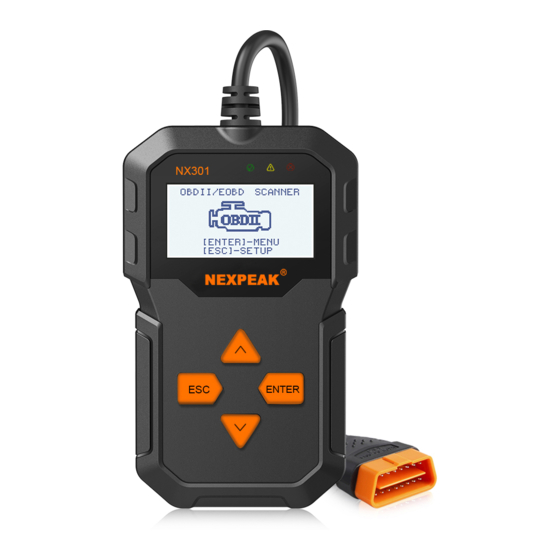
- Page 1 N 301 NEXPEAK N X 301 OBDII Scanner...
-
Page 3: Table Of Contents
2.3 Location of the Data Link Connector (DLC) 2.4 OBD II Readiness Monitors 2.5 OBD II Monitor Readiness Stauts 2.6 OBD II Definitions 3.Using the Scan Tool 3.1 About NEXPEAK NX301 3.2 Specification 3.3 Package Accessories 3.4 Tool Description 3.5 DTC Look-up 3.6 Product Setup... - Page 4 Verzeichnis 1. Sicherheitsvorkehrungen und Warnungen 2. Allgemeine Information 2.1 Über NEXPEAK NX301 2.2 Spezifikation 2.3 Paket Zubehör 3. Verwenden das Scan Werkzeug 3.1 Werkzeug beschreibung 3.2 Sprache einrichten 3.3 Abdeckung Fahrzeug 4. Werkzeug Betrieb1 4.1 Speicherort des Data Link Connector (DLC) 4.2 Starten Diagnose...
-
Page 5: Safety Precautions And Warnings
1.Safety Precautions and Warnings To prevent personal injury or damage to vehicles and/or the scan tool, read this instruction manual first and observe the following safety precautions at a minimum whenever working on a vehicle: • Always perform automotive testing in a safe environment. •... -
Page 6: General Information
2.General Information 2.1 On-Board Diagnostics(OBD)II The first generation of On-Board Diagnostics (called OBD I) was developedby the California Air Resources Board (CARB )and implemented in 1988 tomonitor some of the emission control components on vehicles.As technologyevolved and the desire to improve the On-Board Diagnostic system increased,a new generation of On-Board Diagnostic system was developed,This second generation of On-Board Diagnostic regulations is called "OBD II". -
Page 7: Location Of The Data Link Connector (Dlc)
DTC Example P 0 2 0 2 Systems B=Body Identifying specific C=Chassis malfunctioning P=Powertrain section of the U=Network systems Sub-systems Code Type 1=Fuel and Air Metering Generic (SAE): 2=Fuel and Air Metering P0,P2,P34--P39 3=Ignition System or Engine Misfire B0,B3 4=Auxiliary Emission Controls C0,C3 5=Vehicle Speed Control and Idle U0,U3... -
Page 8: Obd Ii Monitor Readiness Stauts
Currently, there are eleven OBD II Readiness Monitors (or I/M Monitors) defined by the U.S. Environmental Protection Agency(EPA). Not all monitors are supported by all vehicles and the exact number of monitors in any vehicle depends on the motor vehicle manufacturer and their emissions control strategy, Continuous Monitors- Some of the vehicle components or systems are continuously tested by the vehicles's OBD II system, while others are tested only under specific... -
Page 9: Obd Ii Definitions
drive cycle has been performed. The drive cycle that enables a monitor and sets the readiness codes to "Ready" varies for each individual monitor. Once a monitor is set as "Ready" or "Complete",it will remain in this state. A number of factors, including erasing of Diagnostiv Trouble Codes(DTCs) With a scan tool can result in Readiness Monitors being set to "Not Ready". -
Page 10: Using The Scan Tool
State, Emission Monitor Status and solve engine systems and drive ability problems. The car diagnostic functions of NX301 is much more reliable and completely superior to other model, it support full OBDII 10 Modes diagnostics. Besides,... -
Page 11: Specification
2. OBD2 cable - Provides power to tool and communicates between tool and vehicle 3. USB cable - Used to upgrade the scan tool, and to print retrieve 3.4 Tool Description NEXPEAK N X 301 OBDII Scanner 1) OBD IT CONNECTOR - Connects the scan tool to the vehicle's... -
Page 12: Dtc Lookup
6) ESC BUTTON - Returns to previous menu. 7) ENTER BUTTON - Confirms a selection (or action) from a menu list. 8) UP SCROLL BUTTON — Moves UP through menu and sub menu items in menu mode. When more than one screen of data is retrieved, moves UP through the current screen to next screens for additional data. -
Page 13: Product Setup
Main Menu P0000 [ ]-Move to choose [ ]-Change Digit [ENTER]-Confirm [ESC]-Exit 3.6 Product Setup The scan tool allows you to adjust the following settings: 1) Language:Selects the desired language. 2) Contrast Adijustment:Adjusts the contrast of the LCD display. 3) Unit of Measurememt: Sets the unit of measure to Imperial or Metric. - Page 14 From the Main Menu:Use the UP/DOWN scroll button to select System Setup, and press ENTER button. Follow the instructions to make adjustments as described in the following setup options. Main Menu Diagnostics DTC Lookup Review Data Print Data System Setup Tool Information Language Setup English is the default language.
- Page 15 System Setup Language Contrast Unit of Measure Auto Power-off Beep Set Tool Self-test 2) From Contrast menu,use the UP/DOWN scroll button to increase or decrease contrast. Contrast (30%) use or to change 3) Press the ENTER button to save your settings and return to previous menu.
- Page 16 Unit of Measure English Metric 3) Press ENTER button to save your selection and return to previous menu. Beep Set The default setting is been on. 1) From System Setup menu, use UP/DOWN scroll button to select Beep Set and press the ENTER button. System Setup Language Contrast...
- Page 17 System Setup Language Contrast Unit of Measure Auto Power-off Beep Set Tool Self-test 2) Select Display Test from Tool Self-test menu and press the ENTER button. Tool-Self-test Display Test Keyboard Test 3) Press the ETNER button again to start test .Look for missing spots in the solid black characters.
-
Page 18: Vehicle Coverage
Keyboard Test Press any key to start test key: Double [ESC] to return ·If you press and hold the power switch the key name should show up on the screen or reset the scanner(when powered by vehicle batter). If it does no restart the scanner or power off the scanner, the key is not working properly. -
Page 19: Tool Operation
4. Tool Operation 4.1 Start Diagnostics Before using the code reader, make sure to provide power to the code reader.The unit operates on any of the following sources: - 12-volt vehicle power - USB connection to personal computer. 4.1.1 Connecting to Vehicle Power The code reader normally powers on whenever it is connected to the data link connector (DLC). - Page 20 • Pending Codes: Pending codes are referred to as maturing codes that indicate intermittent faults. If the fault does not occur within a certain number of drive cycles (depending on vehicle), the code clears from memory. If a fault occurs a specific number of times, the code matures into a DTC and the MIL illuminates or blinks.
-
Page 21: Erase Codes
Sensor 1 Circuit High Note: If no DTCs are present, the message "No (Pending) Codes Found!" is displayed. If any manufacturer specific or enhanced codes detected, NX301 reads the correct DTC information automatically according to the VIN. 4.3 Erase Codes CAUTION: 1.To clear codes, make sure that the ignition key is switched to ON... - Page 22 A warning message comes up asking for your confirmation. Erase Codes Erase trouble codes! Are you Sure? Press ENTER button to confirm. • If the codes are cleared successfully, an "Erase Done!" confirmation message shows on the display. Erase Codes Erase Done! Press any key to con.
-
Page 23: Live Data
4.4 Live Data 4.4.1 View Data The View Data function allows viewing of live or real time PID data of vehicle's computer module(S). 1) To view live data, use UP/DOWN scroll button to select Live Data from Diagnostic Menu and press ENTER button. Diagnostic Menu 3/11 Read Codes... - Page 24 Viewing Complete Data Set 4) To view complete set of data, use UP/DOWN scroll button to select Complete Data Set from View Data menu and press ENTER button. 5) View live PIDs on the screen. Use UP/DOWN scroll button for more PIDs if an UP or DOWN arrow appears on the screen.
-
Page 25: Record Data
4.4.2 Record Data The Record Data function allows recording vehicle modules' Parameter Identification (FID) data to help diagnose intermittent vehicle problems. A recording includes 5 frames of live data before trigger event and several frames after trigger event. There are two trigger modes used to record data: A. -
Page 26: Playback Data
4.4.3 Playback Data The Playback Data function allows viewing of previously stored PID data. 1) To playback recorded data, use UP/DOWN scroll button to select Playback Data from Live Data menu and press RNTER button. Live Data View Data Record Data Playback Data You are also allowed to playback recorded data immediately after recording. -
Page 27: View Freeze Frame Data
• The number "x/x" to the upper right comer of the screen indicates total number of recorded frames and sequence of frame being displayed. • Negative frames indicate data recorded prior to trigger event, and positive frames indicate data recorded after trigger event. 4.5 View Freeze Frame Data 1) To view freeze frame data, use UP/DOWN scroll button to select View Freeze Frame from Diagnostic Menu and press ENTER button. -
Page 28: Retrieve I/M Readiness Status
• If there is no freeze frame data available, an advisory message "No freeze frame data stored!" shows on the display. 4) If you want to view full name of a PID, use UP/DOWN scroll button to select the PID, and press HELP button. Engine Coolant Temperaturee 5) Wait a few seconds of press any button to return to previous screen. - Page 29 Diagnostic Menu 5/11 Read Codes Erase Codes Live Data View Freeze Frame I/M Readiness O2 Monitor Test 2) If the vehicle supports both types of tests, then both types will be shown on the screen for selection. I/M Readiness Since DTCs Cleared This Drive Cycle 3) Use UP/DOWN scroll button, as necessary, to view the status of...
-
Page 30: Oxygen(O2) Sensor Monitor Test
4.7 Oxygen(O2) Sensor Monitor Test OBD2 regulations set by SAE require that relevant vehicles monitor and test the oxygen (O2) sensors to identify problems related to fuel efficiency and vehicle emissions. These tests are not on-demand tests and they are done automatically when engine operating conditions are within specified limits. - Page 31 3) Use UP/DOWN scroll button to select O2 sensor from O2 Monitor Test menu and press ENTER button. If the vehicle does not support the mode, an advisory message will be displayed on the screen. O2 Monitor Test 02 Mon.B1S1 02 Mon.B1S2 O2 Monitor Test The selected mode is...
-
Page 32: On-Board Monitor Test
4.8 On-Board Monitor Test The On-Board Monitor Test is useful after servicing of after erasing a vehicle's control module memory. The On-Board Monitor Test for non-CAN-equipped vehicles retrieves and displays test results for emission-related power train components and systems that are not continuously monitored. - Page 33 3) From On-Board Mon. Test menu, use UP/DOWN scroll button to select a test to view and press ENTER button. On-Board Mon.Test Test S01 Data Test S05 Data Test S09 Data If the vehicle under test does not support the mode,an advisory message will be displaye on the screen.
-
Page 34: Component Test
For CAN-equipped vehicles, test results displayed can be as below: 02 Heater Mon. B1-S1 SOD TEST MEAS: 10.180(V) MIN: 10.500(V) MAX: 13.800(V) STS: Fall 6) Press ESC button to return to the previous menus. 4.9 Component Test The Component Test function allows initiating a leak test for the vehicle's EVAP system. -
Page 35: View Vehicle Information
3) If the test has been initiated by the vehicle, a confirmation message will be displayed on the screen. Working Command Sent! Pree any key to con. Some vehicles do not allow scan tools to control vehicle systems or components. If the vehicle under test does not support the EVAP Leak Test, an advisory message is displayed on the screen. -
Page 36: Led Interpretation
2) Wait a few seconds while the scan tool reads vehicle information. Vehicle Info. Reading PID... -Please Wait- 3) View retrieved vehicle information on screen. Vehicle Info VIN:161JC544R7252367 CID1:JMB*36761500 CID2:JMB*4787261111 CIN1:1791BC82 CIN2:16E062BE 4) Press ESC button to return previous menu 4.11 LED Interpretation 1) GREEN LED -- indicates the engine system is working normally (all monitors on the vehicle are active and performing their diagnostic... -
Page 37: Print Diagnostic Report
5. Printing Diagnostic Report The Print Data function allows uploading the recorded data by scan tool to windows PC for printing out (Needs Windows PC connecting with printers), you may customized the data/report before printing on computers. To upload the recorded data, you need the following tools: 1.Scan tool 2.A Windows PC or laptop with USB ports. - Page 38 To update your scan tool, you need the following items. 1.Scan tool 2.A PC or laptop with USB ports. (Support only official version windows XP-10, 32/64 Bits OS) 3.USB cable Steps: 1) Download and install the applications from our website: www.nexpeaktech.com Device Driver Installation Wizard Completing the Device Driver...
-
Page 39: Appendix
7. Appendix 7.1 Appendix 1-PID List PID Abbreviation Full Name DTC_CNT DTC Stored Number DTCFRZF FUELSYS1 Fuel System 1 Status FUELSYS2 Fuel System 2 Status LOAD_PCT(%) Calculated Load Value 。 ECT( F) Engine Coolant Temperature 。 ETC( C) Engine Coolant Temperature SHRTFT1(%) Short Term Fuel Trim-Bank1 SHRTFT3(%) - Page 40 PID Abbreviation Full Name AIR-STAT Commanded Secondary Air Status O2SLOC Location of O2 Sensors O2B1S1(V) O2 Sensor Output Voltage(B1S1) SHRTFTB1S1(%) Short Term Fuel Trim(B1S1) O2B1S2(V) O2 Sensor Output Voltage(B1S2) SHRTFTB1S2(%) Short Term Fuel Trim(B1S2) O2B1S3(V) O2 Sensor Output Voltage(B1S3) SHRTFTB1S3(%) Short Term Fuel Trim(B1S3) O2B1S4(V) O2 Sensor Output Voltage(B1S4)
- Page 41 PID Abbreviation Full Name Short Term Fuel Trim(B4S1) SHRTFTB4S1(%) O2 Sensor Output Voltage(B4S2) O2B4S2(V) Short Term Fuel Trim(B4S2) SHRTFRB4S2(%) OBD Require To Whic Vehicle Designed OBDSUP Location Of O2 Sensors O2SLOC Time Since Engine Start RUNTM(sec) Distance Travelled While MIL Activated MIL_DIST(km) Distance Travelled While MIL Activated MIL_DIST(milc)
- Page 42 Full Name PID Abbreviation Equivalence Ratio(wide range O2S)(B2S1) EQ_ RATB2S1 O2 Sensor Voltage(wide range O2S)(B2S1) O2B2S1(V) Equivalence Ratio(wide range O2S)(B2S2) EQ_RATB2S2 O2 Sensor Voltage(wide range O2S)(B2S2) O2B2S2(V) EQ_RATB3S1 Equivalence Ratio(wide range O2S)(B3S1) O2B3S1(V) O2 Sensor Voltage(wide range O2S)(B3S1) EQ_RATB3S2 Equivalence Ratio(wide range O2S)(B3S2) O2B3S2(V) O2 Sensor Voltage(wide range O2S)(B3S2) Equivalence Ratio(wide range O2S)(B4S1)
- Page 43 Full Name PID Abbreviation O2S21(mA) O2 Sensor Current(wide range O2S)(B2S1) EQ_RAT22 Equivalence Ratio(wide range O2S)(B2S2) O2S22(mA) O2 Sensor Current(wide range O2S)(B2S2) EQ_RAT23 Equivalence Ratio(wide range O2S)(B2S3) O2S23(mA) O2 Sensor Current(wide range O2S)(B2S3) EQ_RAT24 Equivalence Ratio(wide range O2S)(B2S4) O2S24(mA) O2 Sensor Current(wide range O2S)(B2S4) EQ_RAT11 Equivalence Ratio(wide range O2S)(B2S1) O2S11(mA)
-
Page 44: Appendix 2-In-Use Performance Tracking Data List
Full Name PID Abbreviation LOAD_ABS(%) Absolute Load Value EQ_RAT Commanded Equivalence Ratio TP_R(%) Relative Throttle Position AAT( F) Ambient Air Temperature AAT( C) Ambient Air Temperature TP_B(%) Absolute Throttle Position B TP_C(%) Absolute Throttle Position C Accelerator Pedal Position D APP_D(%) Accelerator Pedal Position E APP_F(%) - Page 45 Catalyst Monitor Conditions Encountered Counts Bank 2 Catalyst displays ESC number of times Monitor that the vehicle has been operated CATCOND2 Conditions in the specified catalyst Encountered monitoring conditions Counts Bank 2 (denominator) O2 Sensor Monitor Completion Counts Bank 1displays ESC O2 Sensor number of time that all conditions Monitor...
-
Page 46: Service Procedures
AIR Monitor CompletionCondition AIR Monitor Counts (Secondary Air) displays Completion ESC number of times that all AIRCOMP Condition Counts conditions necessary to detect an (Secondary Air) AIR system malfuncion have been encountered (numberator). AIR Monitor Conditions AIR Monitor Encountered Counts (Secondary Conditions Aiir) displays ESC number of time Encountered... -
Page 47: Sicherheitsvorkehrungen Und Warnungen
1. Sicherheitsvorkehrungen und Warnungen Um Personen oder Sachschäden an Fahrzeugen und / oder am Diagnosegerät zu vermeiden, lesen Sie zuerst diese Bedienungsanleitung und beachten Sie mindestens die folgenden Sicherheitsvorkehrungen,wenn Sie an einem Fahrzeug arbeiten: • Führen Sie immer Automobil Tests in einer sicheren Umgebung durch. -
Page 48: Allgemeine Information
2.1 Über NEXPEAK NX301 NEXPEAK NX301 Mit den einzigartigen patentierten logischen Navigationstasten, Bildschirm mit TFT-Hintergrundbeleuchtung und eingebautem Lautsprecher. Der NEXPEAK NX301 ist die ultimative Leichtigkeit und Erschwinglichkeit,Benutzern ermöglichen, Reparaturen, Straßentest, Zustand zu überprüfen, Emissionsmonitor Status und lösen Motorsysteme und Fahrbarkeit Probleme. Die Auto-Diagnose funktionen des NX301 sind viel zuverlässiger und... -
Page 49: Verwenden Das Scan Werkzeug
4.Schützende Plüsch Tasche - Eine PlüschTasche, um das Werkzeug zu lagern, wenn es nicht benutzt wird 3. Verwenden das Scan Werkzeug 3.1 Werkzeug beschreibung NEXPEAK N X 301 OBDII Scanner 1) OBD II CONNECTOR - Verbindet den Diagnosetester mit dem Data Link Connector (DLC) des Fahrzeugs. -
Page 50: Sprache Einrichten
6) ESC TASTE- Kehrt zum vorherigen Menü zurück 7) EINGABETASTE- Bestätigt eine Auswahl (oder Aktion) aus einer Menüliste 8) AUFWÄRTSSCROLLEN TASTE- Bewegt sich im Menümodus durch Menü- und Untermenüpunkte nach oben. Wenn mehr als ein Bildschirm von Daten abgerufen wird, wird durch den aktuellen Bildschirm auf die nächsten Bildschirme für zusätzliche Daten verschoben. -
Page 51: Abdeckung Fahrzeug
Benutzeroberfläche angezeigt: Sie können die AUFWÄRTS / ABWÄRTS-Taste drücken, um eine beliebige Sprache auszuwählen und die OK-Taste zur Bestätigung drücken. Das System konvertiert sofort zur ausgewählten Sprachschnittstelle. 3.3 Abdeckung Fahrzeug Das Scan-Tool wurde speziell für die Verwendung mit allen OBD II-konformen Fahrzeugen entwickelt, einschließlich Control Area Network (CAN), Die EPA schreibt vor, dass alle 1996 und neueren Fahrzeuge (Pkw und leichte Nutzfahrzeuge), die in den USA verkauft werden, OBD II-konform sein müssen. -
Page 52: Werkzeug Betrieb1
4. Werkzeug Betrieb 4.1 Speicherort des Data Link Connector (DLC) Der DLC (Data Link Connector oder Diagnostic Link Connector) ist der standardisierte 16-fach-Steckverbinder, an dem Diagnose-Scan-Tools für die meisten Fahrzeuge mit der Fahrzeugseite verbunden sind. Wenn sich der Data Link Connector nicht unter dem Dashboard befindet, sollte eine Beschriftung vorhanden sein, die den Speicherort angibt. - Page 53 Hauptmen Diagnose DTC Anzeige Daten nochmal anseh Daten drucken Systemeinstellungen äteinformation 6) Drücken Sie die EINGABE-Taste, um zu bestätigen, dass eine Reihe von Meldungen mit den OBD2-Protokollen auf dem Display angezeigt wird, bis das Fahrzeugprotokoll erkannt wird. Wenn der Diagnose-Tester nicht mit der ECU des Fahrzeugs (Motorsteuergerät) kommunizieren kann, erscheint die Meldung "LINKING ERROR!"...
-
Page 54: Codes Lesen
System status MIL Status Kodes Gefunden Mon. arbeit nicht Monitor OK Mon.nicht Komp1 4.3 Codes lesen • Das Lesen von Codes kann mit dem Schlüssel bei laufendem Motor (KOER) erfolgen. • Gespeicherte Codes werden auch als "harte Codes" oder "permanente Codes" bezeichnet. Diese Codes veranlassen das Steuermodul, die Störungsanzeigelampe (MIL) zu erleuchten, wenn ein emissionsbedingter Fehler auftritt. - Page 55 Fehlercodes Gespeicherte daten Offene Codes • Wenn keine Diagnose-Fehlercodes vorhanden sind, zeigt das Display "Keine (ausstehenden) Codes sind im Modul gespeichert!" Warten Sie einige Sekunden oder drücken Sie eine beliebige Taste, um zum Diagnosemenü zurückzukehren. 3) Zeigen Sie DTCs und ihre Definitionen auf dem Bildschirm an. Die Nummer des Steuermoduls, die Reihenfolge der DTCs, die Gesamtzahl der erkannten Codes und die Art des Codes (generisch oder herstellerspezifisch) werden in der oberen rechten Ecke des...
-
Page 56: Codes Löschen
Fahrzeughersteller 1/28 FORRE CHRYSLER BENZ VW/AUDI • Wenn mehr als ein DTC gefunden wird, verwenden Sie die AUFWÄRTS / ABWÄRTS-Taste, falls erforderlich, bis alle Codes angezeigt wurden. 4.4 Codes löschen VORSICHT: Das Löschen der Diagnose-Fehlercodes kann dem Diagnose-Tester ermöglichen, nicht nur die Codes vom Bordcomputer des Fahrzeugs zu löschen, sondern auch die "Freeze Frame"... -
Page 57: Lebensdaten
Wenn Sie nicht mit dem Löschen von Codes fortfahren möchten, drücken Sie die ESC-Taste oder verwenden Sie die AUFWÄRTS / ABWÄRTS-Tasten zum Auswählen von NO, um das Menü zu verlassen. Eine Nachricht von "Command Can celled!" Auftritte. Warten Sie einige Sekunden oder drücken Sie eine beliebige Taste, um zum Diagnosemenü... - Page 58 Live Daten Datenanzeige Datenaufzeichnung Datenwiedergabe Live Daten L e s e P I D . . . 0 6 - B i t t e w a r t e n - 4) Um den vollständigen Datensatz anzuzeigen, verwenden Sie die AUFWÄRTS / ABWÄRTS-Taste, um im Menü...
-
Page 59: Daten Aufzeichnen
Wenn das Symbol angezeigt wird, wenn eine PID markiert ist, bedeutet dies, dass Grafikinformationen verfügbar sind. Drücken Sie ENTER, um das Diagramm anzuzeigen. RPM(/min) 1725 6) Drücken Sie die ESC-Taste, um zum vorherigen Menü zurückzukehren. Sie dürfen maximal 18 PIDs aufnehmen, wenn die ausgewählten PIDs 18 überschreiten, a "Die ausgewählte Datenliste ist voll!"... -
Page 60: Wiedergabe Daten
Der Scantool zeichnet PID-Daten auf, bis der Benutzer die ESC-Taste drückt, der ausgewählte Speicherplatz voll ist oder die Aufnahme beendet ist. Eine Aufforderung zur Wiedergabe von Daten wird auf dem Bildschirm angezeigt. 4.5.3 Wiedergabe Daten Die Wiedergabedaten-Funktion ermöglicht die Anzeige zuvor gespeicherter PID-Daten. -
Page 61: Aussicht Gefrorener Rahmen Daten
Datenwiedergabe 1/312 DTC_CNT FUEL SYS1 FUEL SYS2 LOAD_PCT(%) SHRTFT1(%) 48.4 DTC_CNT Die Zahl "x / x" in der oberen rechten Ecke des Bildschirms zeigt die Gesamtzahl der aufgezeichneten Frames und die Sequenz des angezeigten Frames an. Negative Frames zeigen Daten an, die vor dem Triggerereignis aufgezeichnet wurden, und positive Frames zeigen Daten an, die nach dem Triggerereignis aufgezeichnet wurden. -
Page 62: Abrufen I/M Bereitschaft Status
3) Wenn in Formation abgerufen deckt mehr als offenen Bildschirm, dann erscheint ein Pfeil nach unten. Verwenden Sie ggf. die ABWÄRTS-Taste, bis alle Daten angezeigt wurden. Wenn keine Gefrorener Rahmen Daten verfügbar sind, wird die Meldung "Keine Gefrorener Rahmen Daten gespeichert!" erscheint auf dem Display. - Page 63 "OK" - Zeigt an, dass ein bestimmter Monitor, der geprüft wird, seinen Diagnosetest abgeschlossen hat. "INC" - Zeigt an, dass ein bestimmter Monitor, der geprüft wird, seine Diagnoseprüfung nicht abgeschlossen hat. "N/A" - Der Monitor wird von diesem Fahrzeug nicht unterstützt. 1) Verwenden Sie die AUFWÄRTS / ABWÄRTS-Tasten, um I / M Readiness vom Diagnosemenü...
-
Page 64: Sauerstoff (O2) Sensor Monitor Prüfung
• Sec Air System - Sekundärluftüberwachung • Htd Catalyst - Heizkatalysatormonitor • A / C Refrig Mon – Systemmonitor 4) Drücken Sie die ESC-Taste, um zum Diagnosemenü zurückzukehren. 4.8 Sauerstoff (O2) Sensor Monitor Prüfung Die O2-Monitor-Testfunktion ermöglicht die Abfrage und Anzeige von O2-Sensormonitor-Testergebnissen für die zuletzt durchgeführten Tests vom Bordcomputer des Fahrzeugs. - Page 65 Wenn das Fahrzeug den Modus nicht unterstützt, wird eine Hinweismeldung auf dem Bildschirm angezeigt. Lamdasonde Pr üfung 02 Mon. B1S1 02 Mon. B1S2 O2 Mon. B1S1 Der gewählte Modus wirdnicht unterstützt Jeder Taste fortsetze 4) Zeigen Sie die Testergebnisse des ausgewählten O2-Sensors an. O2 Mon.
-
Page 66: Am-Bordmonitor Prüfung
4.9 Am-Bordmonitor Prüfung Der On-Board-Monitor-Test ist nach einer Wartung nützlich, nachdem der Speicher eines Fahrzeugsteuermoduls gelöscht wurde. Der On-Board-Monitor-Test für nicht mit CAN ausgerüstete Fahrzeuge liefert Testergebnisse für emissionsbezogene Antriebsstrangkomponenten und Systeme, die nicht ständig überwacht werden, und zeigt diese an. Der On-Board-Monitor-Test für mit CAN ausgerüstete Fahrzeuge liefert Testergebnisse für emissionsbezogene Antriebsstrangkomponenten und -systeme, die ständig überwacht werden und nicht überwacht werden, und zeigt... - Page 67 3) Von On-Board Mon.Testen Sie das Menü, verwenden Sie die AUFWÄRTS/ABWÄRTS -Taste, um einen Test zur Ansicht auszuwählen, und drücken Sie die ENTER-Taste. Monitor prüfung Test S01 Daten Test S05 Daten Test S09 Daten Wenn das zu testende Fahrzeug den Modus nicht unterstützt, wird eine Hinweismeldung auf dem Bildschirm angezeigt.
-
Page 68: Komponenten Prüfung
Für mit CAN ausgerüstete Fahrzeuge können folgende Testergebnisse angezeigt werden: Catalyst Mon.B1 Mager bis reich sensor(V) MEAS : 6.0540(V) 3.4071(V) MAX : 4.1642(V) Fall 6) Drücken Sie die ESC-Taste, um zu den vorherigen Menüs zurück zu kehren. 4.10 Komponenten Prüfung Die Komponententestfunktion ermöglicht das Einleiten eines Lecktests für das EVAP-System des Fahrzeugs. -
Page 69: Ansicht Fahrzeuginformationen
2) Wählen Sie im Komponententest mit der Taste AUFWÄRTS/ABWÄRTS den Test aus, der gestartet werden soll. Komponenten prüfung Evap Leak Pr fung ü 3) Wenn der Test vom Fahrzeug initiiert wurde, wird eine Bestätigungs meldung auf dem Bildschirm angezeigt. Einige Fahrzeuge erlauben keine Scan-Tools zur Steuerung von Fahrzeugsystemen oder -komponenten. - Page 70 1) Verwenden Sie die AUF / AB-tasten, um Fahrzeuginformationen aus dem Diagnosemenü auszuwählen und drücken Sie die ENTER-Taste. Diagnosemen ü 9/11 üfung Monitor pr Komponenten prüfung Fahrzug Info Modul verfügbar MaßEinheit 2) Warten Sie ein paar Sekunden, während das Diagnose-Tool die Fahrzeug informationen liest.
-
Page 71: Led Deutung
4.12 LED Deutung 1) GRÜNE LED - Zeigt an, dass die Motorsysteme "OK" sind und normal funktionieren (die Anzahl der vom Fahrzeug unterstützten Monitore, die ihre Selbstdiagnosetests ausgeführt haben und ausführen, liegt innerhalb des erlaubten Grenzwerts. MEL ist ausgeschaltet). Es gibt keine gespeicherten und ausstehenden DTCs. Das Fahrzeug ist bereit für einen Emissionstest und es besteht eine gute Möglichkeit, dass es zertifiziert werden kann. -
Page 72: Drucken Diagnose Bericht
5. Drucken Diagnose bericht Die Funktion "Daten drucken" ermöglicht das Hochladen der aufgezeichneten Daten per Scan-Tool an Windows-PCs zum Ausdrucken (Windows-PC muss mit Druckern verbunden sein). Sie können die Daten / Berichte vor dem Drucken auf dem Computer anpassen. Um die aufgezeichneten Daten hochzuladen, benötigen Sie folgende Tools: 1.Scan-Werkzeug 2.A Windows PC or laptop with USB ports. -
Page 73: Aktualisieren Das Scan Werkzeug
6. Aktualisieren Das Scan Werkzeug Mit dieser Funktion können Sie die Software des Diagnose-Tools und die DTC-Bibliothek über einen Windows-Computer aktualisieren. Ihr Scan-Tool zu aktualisieren, benötigen Sie die folgenden Elemente. 1.Scan-Werkzeug 2.Ein PC oder Laptop mit USB-Anschlüssen. (Support nur offizielle Version Windows XP-10, 32/64 Bits OS) 3.USB-Kabel Schritte:... -
Page 74: Blinddarm
7. Blinddarm 7.1 Anhang 1-PID-Liste PID Abbreviation Full Name DTC_CNT DTC Stored Number DTCFRZF FUELSYS1 Fuel System 1 Status FUELSYS2 Fuel System 2 Status LOAD_PCT(%) Calculated Load Value 。 ECT( F) Engine Coolant Temperature 。 ETC( C) Engine Coolant Temperature SHRTFT1(%) Short Term Fuel Trim-Bank1 SHRTFT3(%) - Page 75 PID Abbreviation Full Name AIR-STAT Commanded Secondary Air Status O2SLOC Location of O2 Sensors O2B1S1(V) O2 Sensor Output Voltage(B1S1) SHRTFTB1S1(%) Short Term Fuel Trim(B1S1) O2B1S2(V) O2 Sensor Output Voltage(B1S2) SHRTFTB1S2(%) Short Term Fuel Trim(B1S2) O2B1S3(V) O2 Sensor Output Voltage(B1S3) SHRTFTB1S3(%) Short Term Fuel Trim(B1S3) O2B1S4(V) O2 Sensor Output Voltage(B1S4)
- Page 76 PID Abbreviation Full Name Short Term Fuel Trim(B4S1) SHRTFTB4S1(%) O2 Sensor Output Voltage(B4S2) O2B4S2(V) Short Term Fuel Trim(B4S2) SHRTFRB4S2(%) OBD Require To Whic Vehicle Designed OBDSUP Location Of O2 Sensors O2SLOC Time Since Engine Start RUNTM(sec) Distance Travelled While MIL Activated MIL_DIST(km) Distance Travelled While MIL Activated MIL_DIST(milc)
- Page 77 Full Name PID Abbreviation Equivalence Ratio(wide range O2S)(B2S1) EQ_RATB2S1 O2B2S1(V) O2 Sensor Voltage(wide range O2S)(B2S1) EQ_RATB2S2 Equivalence Ratio(wide range O2S)(B2S2) O2B2S2(V) O2 Sensor Voltage(wide range O2S)(B2S2) Equivalence Ratio(wide range O2S)(B3S1) EQ_RATB3S1 O2 Sensor Voltage(wide range O2S)(B3S1) O2B3S1(V) EQ_RATB3S2 Equivalence Ratio(wide range O2S)(B3S2) O2B3S2(V) O2 Sensor Voltage(wide range O2S)(B3S2) EQ-RATB4S1...
- Page 78 Full Name PID Abbreviation O2S21(mA) O2 Sensor Current(wide range O2S)(B2S1) EQ_RAT22 Equivalence Ratio(wide range O2S)(B2S2) O2S22(mA) O2 Sensor Current(wide range O2S)(B2S2) EQ_RAT23 Equivalence Ratio(wide range O2S)(B2S3) O2S23(mA) O2 Sensor Current(wide range O2S)(B2S3) EQ_RAT24 Equivalence Ratio(wide range O2S)(B2S4) O2S24(mA) O2 Sensor Current(wide range O2S)(B2S4) EQ_RAT11 Equivalence Ratio(wide range O2S)(B2S1) O2S11(mA)
-
Page 79: Anhang 2 Liste Der Daten Zur Leistungs Überwachung Nach Gebrauch
Full Name PID Abbreviation LOAD_ABS(%) Absolute Load Value EQ_RAT Commanded Equivalence Ratio TP_R(%) Relative Throttle Position AAT( F) Ambient Air Temperature AAT( C) Ambient Air Temperature TP_B(%) Absolute Throttle Position B Absolute Throttle Position C TP_C(%) Accelerator Pedal Position D APP_D(%) Accelerator Pedal Position E APP_F(%) - Page 80 Catalyst Monitor Conditions Encountered Counts Bank 2 Catalyst displays ESC number of times Monitor that the vehicle has been operated CATCOND2 Conditions in the specified catalyst Encountered monitoring conditions Counts Bank 2 (denominator) O2 Sensor Monitor Completion Counts Bank 1displays ESC O2 Sensor number of time that all conditions Monitor...
-
Page 81: Dienst Verfahren
AIR Monitor CompletionCondition AIR Monitor Counts (Secondary Air) displays Completion ESC number of times that all AIRCOMP Condition Counts conditions necessary to detect an (Secondary Air) AIR system malfuncion have been encountered (numberator). AIR Monitor Conditions AIR Monitor Encountered Counts (Secondary Conditions Aiir) displays ESC number of time Encountered... - Page 83 NEXPEAK Techonology Co., Ltd. : www.nexpeaktech. com : support@ nexpeaktech.com : www.facebook. com/nexpeaktech : www.twitter. com/nexpeak_ tech...
Need help?
Do you have a question about the NX301 and is the answer not in the manual?
Questions and answers