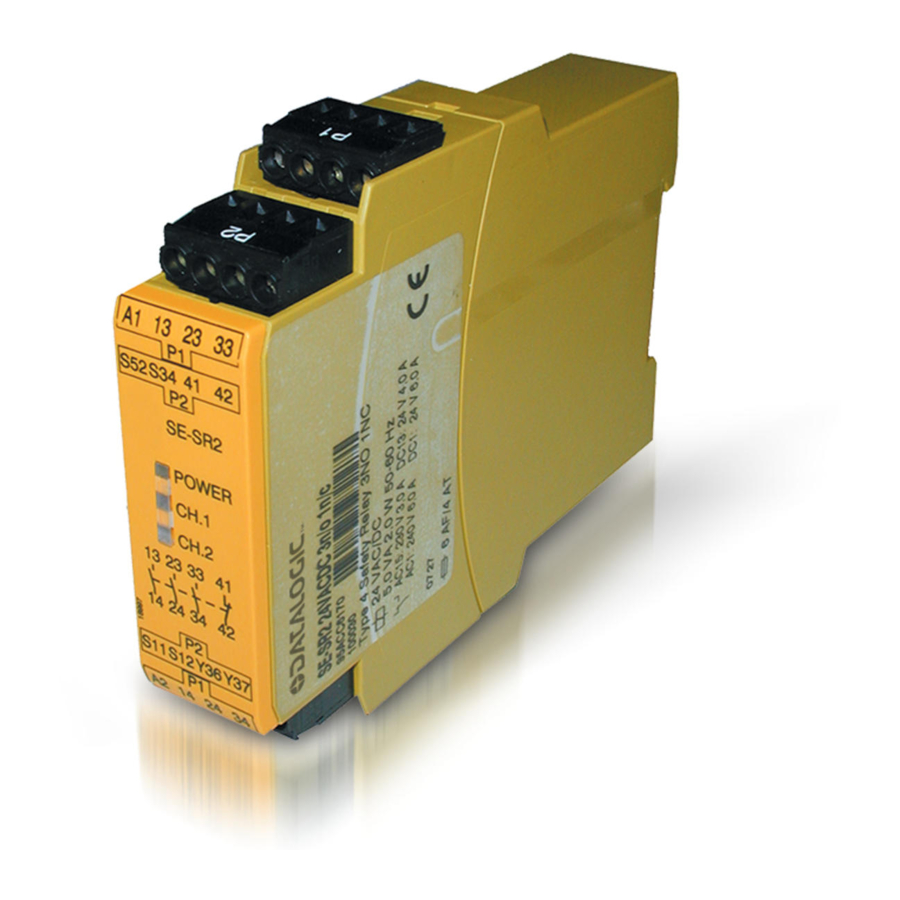
Datalogic SE-SR2 Manual
Safety relays
Hide thumbs
Also See for SE-SR2:
- Operating instructions manual (16 pages) ,
- Operation manual (61 pages)
Table of Contents
Advertisement
Advertisement
Table of Contents

Subscribe to Our Youtube Channel
Summary of Contents for Datalogic SE-SR2
- Page 1 SE-SR2 Safety relays 22 224-06...
-
Page 2: Table Of Contents
Unit features Safety features Block diagram/terminal configuration Function Description Operating modes Timing diagram Installation Wiring Preparing for operation Operation Status indicators Faults – Interference Dimensions in mm Technical details Safety characteristic data Supplementary data Service life graph Operating instructions SE-SR2 826002433-EN-Rev.C... - Page 3 Contents Remove plug-in terminals Order reference EC declaration of conformity Operating instructions SE-SR2 826002433-EN-Rev.C...
-
Page 4: Introduction
SE-SR2 Introduction Validity of documentation This documentation is valid for the product SE-SR2. It is valid until new documentation is published. This operating manual explains the function and operation, describes the installation and provides guidelines on how to connect the product. -
Page 5: Safety
Safety Intended use The safety relay SE-SR2 provides a safety-related interruption of a safety circuit. The safety relay meets the requirements of EN 60947-5-1, EN 60204-1 and VDE 0113‑1 and may be used in applications with light grids. The following is deemed improper use in particular:... -
Page 6: Warranty And Liability
Note for overvoltage category III: If voltages higher than low voltage (>50 VAC or >120 VDC) are present on the unit, connected control elements and sensors must have a rated insulation voltage of at least 250 V. Operating instructions SE-SR2 826002433-EN-Rev.C... -
Page 7: Unit Features
The correct opening and closing of the safety function relays is tested automatically in each on-off cycle. Block diagram/terminal configuration Y36 Y37 S34 SE-SR2 Y36Y37 *Insulation between the non-marked area and the relay contacts: Basic insulation (over- voltage category III), Protective separation (overvoltage category II) Operating instructions SE-SR2 826002433-EN-Rev.C... -
Page 8: Function Description
SE-SR2 Function Description The relay SE-SR2 provides a safety-oriented interruption of a safety circuit. When operating voltage is supplied the "POWER" LED will light up. The unit is ready for operation when the start circuit S12-S34 is closed. Input circuit is closed (e.g. light grid not interrupted): –... -
Page 9: Installation
The power supply must comply with the regulations for extra low voltages with protect- ive electrical separation (SELV, PELV) in accordance with VDE 0100, Part 410. Ensure the wiring and EMC requirements of EN 60204-1 are met. Operating instructions SE-SR2 826002433-EN-Rev.C... -
Page 10: Preparing For Operation
Light grid, detection of shorts across contacts via ESPE NOTICE Operation with a light grid It must not be possible to switch off the supply voltage for the SE-SR2 sep- arately from the supply voltage for the light grid. Start circuit Single-channel... -
Page 11: Operation
SIL CL 3/PL e at least 1x per month for SIL CL 2/PL d at least 1x per year Status indicators LEDs indicate the status and errors during operation: LED on POWER Supply voltage is present. CH.1 Safety contacts of channel 1 are closed. Operating instructions SE-SR2 826002433-EN-Rev.C... -
Page 12: Faults - Interference
Voltage tolerance -15 %/+10 % Output of external power supply (DC) Residual ripple DC 160 % Duty cycle 100 % Max. inrush current impulse Current pulse, A1 1,7 A Pulse duration, A1 3,3 ms Inputs Number Operating instructions SE-SR2 826002433-EN-Rev.C... - Page 13 0,01 A Max. current Max. power 150 W Utilisation category In accordance with the standard EN 60947-5-1 Utilisation category of safety contacts AC15 at 230 V Max. current DC13 (6 cycles/min) at 24 V Max. current Operating instructions SE-SR2 826002433-EN-Rev.C...
- Page 14 With monitored start typ. 30 ms With monitored start max. 50 ms Delay-on de-energisation With E-STOP typ. 10 ms With E-STOP max. 20 ms With power failure typ. 70 ms With power failure max. 120 ms Operating instructions SE-SR2 826002433-EN-Rev.C...
- Page 15 Mounting area (e.g. control cabinet) IP54 Mechanical data Mounting position Mechanical life 10,000,000 cycles Material Bottom PPO UL 94 V0 Front ABS UL 94 V0 PPO UL 94 V0 Connection type Screw terminal Mounting type plug-in Operating instructions SE-SR2 826002433-EN-Rev.C...
-
Page 16: Safety Characteristic Data
PAScal software tool to calculate the safety function's SIL/PL values. Supplementary data CAUTION! It is essential to consider the relay's service life graphs. The relay outputs' safety-related characteristic data is only valid if the values in the service life graphs are met. Operating instructions SE-SR2 826002433-EN-Rev.C... - Page 17 If the service life graphs are not accessible, the stated PFH value can be used irrespective of the switching frequency and the load, as the PFH value already considers the relay's B10d value as well as the failure rates of the other components. Operating instructions SE-SR2 826002433-EN-Rev.C...
-
Page 18: Service Life Graph
The wear is mainly caused by the electrical load; the mechanical load is negli- gible. Switching current (A) Fig.: Service life graphs at 24 VDC and 230 VAC Switching current (A) Fig.: Service life graphs at 110 VDC Operating instructions SE-SR2 826002433-EN-Rev.C... - Page 19 Procedure: Insert the screwdriver into the housing recess behind the terminal and lever the terminal out. Do not remove the terminals by pulling the cables! Order reference Product type Features Connection type Order No. SE-SR2 24 VDC Screw terminals 95ACC6170 Operating instructions SE-SR2 826002433-EN-Rev.C...
- Page 20 Apparatus / Apparato / Aparato / Appareil / Gerätetyp / Apparaatmodel / Apparatmodell SE-SR2; EMERGENCY - STOP SAFETY DEVICE and all its models / e tutti i suoi modelli / y todos sus modelos / et tous ses modèles / und seine modelle / en al haar modellen / och alla sina modeller Manufacturer / Produtore / Fabricante / Fabricant / Hersteller / Fabrikant / Tillverkaren Datalogic S.r.l.
- Page 21 Back cover...


Need help?
Do you have a question about the SE-SR2 and is the answer not in the manual?
Questions and answers