
Related Manuals for AlazarTech ATS9353

Summary of Contents for AlazarTech ATS9353
- Page 1 ATS9353 User Manual 12-Bit, 2 Channel, 500 MS/s Waveform Digitizer for PCI Express Gen 2 Bus User Manual Version 1.1 Written for Hardware Version 1.1 November 2020 Edition...
- Page 2 Canada H9R 4S2 Telephone: (514) 426-4899 Fax: (514) 426-2723 E-mail: sales@alazartech.com Web site: www.alazartech.com To comment on the documentation for ATS9353, send an e-mail to support@alazartech.com Information required when contacting AlazarTech for technical support: Owned by: Serial Number: Purchase Date: Purchased From:...
- Page 3 The reader should consult AlazarTech if errors are suspected. In no event shall AlazarTech be liable for any damages arising out of or related to this document or the information contained in it. The latest user manual can be found on the AlazarTech website at www.alazartech.com/support/downloads.htm.
- Page 4 LIABLE FOR DAMAGES RESULTING FROM LOSS OF DATA, PROFITS, USE OF PRODUCTS, OR INCIDENTAL OR CONSEQUENTIAL DAMAGES, EVEN IF ADVISED OF THE POSSIBILITY THEREOF. This limitation of the liability of AlazarTech will apply regardless of the form of action, whether in contract or tort, including negligence. Any action against AlazarTech must be brought within one year after the cause of action accrues.
- Page 5 Copyright © 2020 Alazar Technologies Inc. Warning Regarding Use of AlazarTech Products ALAZARTECH PRODUCTS ARE NOT DESIGNED WITH COMPONENTS AND TESTING FOR A LEVEL OF RELIABILITY SUITABLE FOR USE IN OR IN CONNECTION WITH SURGICAL IMPLANTS OR AS CRITICAL COMPONENTS IN ANY LIFE SUPPORT SYSTEMS WHOSE FAILURE TO PERFORM CAN REASONABLY BE EXPECTED TO CAUSE SIGNIFICANT INJURY TO A HUMAN.
-
Page 6: Compliance
FCC Class A products can be operated. FCC Class B products display either an FCC ID code, starting with the letters EXN, or the FCC Class B compliance mark. Consult the FCC website https://www.fcc.gov/ for more information. ATS9353 User Manual... - Page 7 Classification requirements are the same for the Federal Communications Commission (FCC) and Innovation, Science and Economic Development (ISED) Canada. Changes or modifications not expressly approved by AlazarTech Inc. could void the user’s authority to operate the equipment under the FCC/ISED Rules. Class A...
- Page 8 To obtain the DoC for this product, click Declaration of Conformity at www.alazartech.com/support/documents.htm. This web page lists all DoCs by product family. Select the appropriate product to download or read the DoC. Certain exemptions may apply in the USA, see FCC Rules §15.103 Exempted devices, and §15.105(c).
-
Page 9: Table Of Contents
What You Need to Get Started ............9 Unpacking .................. 10 Installing the ATS9353 in Windows ..........11 Installing the ATS9353 in a Linux System ........19 Updating ATS9353 Driver ............. 23 Updating ATS9353 Firmware in Windows ........24 Updating ATS9353 Firmware in a Linux System ......30 CHAPTER 3: HARDWARE OVERVIEW ........ -
Page 10: Change Log
Copyright © 2020 Alazar Technologies Inc. Change Log This is the first edition of this manual. ATS9353 User Manual... -
Page 12: Chapter 1: Introduction
Copyright © 2020 Alazar Technologies Inc. Chapter 1: Introduction This chapter describes the ATS9353 and lists additional equipment. ATS9353 User Manual... -
Page 13: About Your Ats9353
Copyright © 2020 Alazar Technologies Inc. About Your ATS9353 Thank you for your purchase of an ATS9353. This PCI Express (PCIe Gen 2 x4) based waveform digitizer has the following features: • Two 12-bit resolution analog input channels • Real-time sampling rate of 500 MS/s to 1 KS/s with internal clock and 500 MS/s to 25 MS/s with external clock •... -
Page 14: Ats9353 Export Control Classification
Area Control List Sanctions List. Furthermore, if the end-use of ATS9353, in part or in its entirety, is related to the development or deployment of weapons of mass destruction, AlazarTech is obliged to apply for an export permit. ATS9353 User Manual... -
Page 15: Acquiring Data With Your Ats9353
ATS9353 or interactively with the AlazarDSO software for Windows or with AlazarFrontPanel for Linux. Note that AlazarFrontPanel has a limited feature set. If you want to integrate the ATS9353 in your test and measurement or embedded OEM application, you can program the digitizer using C/C++, Python, ®... - Page 16 Interactively Controlling your ATS9353 The AlazarDSO oscilloscope emulation software for Windows allows you to interactively control your ATS9353 as you would a desktop oscilloscope. Under Linux, the AlazarFrontPanel application is available. Note that Alazar Front Panel has a limited feature set.
- Page 17 AlazarTech designed ATS-GPU to eliminate this software bottleneck so that data can be moved from AlazarTech digitizers to GPUs and from GPUs to user buffers at full PCIe bus speeds. Once the data is available in GPU memory, many types of digital signal processing (DSP) can be done on this data at near-hardware speeds.
-
Page 18: Optional Upgrades
Copyright © 2020 Alazar Technologies Inc. Optional Upgrades AlazarTech offers the following upgrades and accessories for use with your ATS9353 digitizer: • ATS9353: One Year Extended Warranty ATS9353 User Manual... -
Page 19: Chapter 2: Installation And Configuration
Copyright © 2020 Alazar Technologies Inc. Chapter 2: Installation and Configuration This chapter describes how to unpack, install, and configure your ATS9353. ATS9353 User Manual... -
Page 20: What You Need To Get Started
Copyright © 2020 Alazar Technologies Inc. What You Need to Get Started To set up and use your ATS9353, you will need the following: • One or more ATS9353 digitizers • ATS9353 Installation Software on USB Disk (or downloaded software from www.alazartech.com/Support/Downloads) Note: OEM-quantity orders (p/n ATS9353-110, ATS9353-125, ATS9353-150, ATS9353-200) do not come with the USB flash drive. -
Page 21: Unpacking
• Remove the digitizer from the package and inspect the digitizer for loose components or any other sign of damage. Notify AlazarTech if the digitizer appears damaged in any way. Do not install a damaged digitizer into your computer. -
Page 22: Installing The Ats9353 In Windows
The ATS-SDK software development kit, which enables you to programmatically control the ATS9353 b. The ATS-GPU library, which enables you to perform real-time processing of data from the ATS9353 on a CUDA-compatible GPU The following paragraphs will guide you through this process in a step-by-step manner. - Page 23 4-lane ATS9353 card is compatible with any 4-lane, 8-lane or 16-lane connector on the motherboard. Make sure that your computer is powered off before you attempt to insert the ATS9353 digitizer in one of the free PCI Express slots. For best noise performance, leave as much room as possible between your ATS9353 and other hardware.
- Page 24 PCIe card and will attempt to install the device driver if found on the computer. a) If the ATS9353 device driver is not found, Windows will display the following dialog box Click Close.
- Page 25 Insert the installation disk that is supplied on a USB flash drive. If It does not auto-run, manually run the Autorun.exe program on the USB flash drive. The following splash screen will be displayed. Click Install Driver. c) The Select Driver window will appear. Select ATS9353 and click OK . ATS9353 User Manual...
- Page 26 Copyright © 2020 Alazar Technologies Inc. d) The User Account Control pop-up window will show up asking for installation permissions. Click YES to continue installation. e) Windows will install the ATSApi library. ATS9353 User Manual...
- Page 27 ‘Windows Security’ screen. Press install, after optionally checking ‘Always trust software from Alazar Technologies Inc.’ Note 1: If you have Windows 10 v.1607 or later, you cannot install AlazarTech driver versions older than 6.0.0. This is normal behavior. This limitation is due to Microsoft’s driver code signing policy change, which now requires a SHA-2 code...
- Page 28 Copyright © 2020 Alazar Technologies Inc. h) The ATS9353 Device Installer box will display the installation progress of the driver files. Congratulations! The following final screen will confirm that the driver has been successfully installed. ATS9353 User Manual...
- Page 29 3. Install AlazarDSO software that allows you to setup the hardware, acquire signals and view and archive them If you are installing from the USB flash drive shipped with the ATS9353 digitizer, run the Autorun.exe: • Click on Install AlazarDSO •...
-
Page 30: Installing The Ats9353 In A Linux System
4-lane ATS9353 card is compatible with any 4-lane, 8-lane or 16-lane connector on the motherboard. Make sure that your computer is powered off before you attempt to insert the ATS9353 digitizer in one of the free PCI Express slots. For best noise performance, leave as much room as possible between your ATS9353 and other hardware. - Page 31 “x86_64” architecture on CentOS is contained in the “drivers-ats9353-dkms-7.1.2.x86_64.rpm” file. Note: Beginning with driver version 7.1.2, AlazarTech Linux drivers use DKMS to not be dependent on the exact kernel version that the host machine is running. ATS9353 User Manual...
- Page 32 To install packages for ATS9353 on your Linux system, follow these steps: 1. Once you have connected one or several ATS9353 in your computer, power it on.
- Page 33 Copyright © 2020 Alazar Technologies Inc. Installation Troubleshooting If you are experiencing difficulties using AlazarTech digitizers on your Linux system, please ensure that the following packages are all installed: • alazar-front-panel • libats • driver package for your board (with the corresponding distribution)
-
Page 34: Updating Ats9353 Driver
The exact name on disk of a given package file depends on the computer architecture for which it is built, the Linux distribution used, and the actual software version. For example, the driver for ATS9353 version 7.1.2 built for the “x86_64” architecture on CentOS is contained in the “drivers ats9353 dkms 7.1.2.x86_64.rpm”... -
Page 35: Updating Ats9353 Firmware In Windows
• Down on the product’s page, from the Software section: 1. Download the Firmware Update Utility 2. Download the Firmware file – E.g.: ATS9353 Firmware • Unarchive both files. Make sure that the Windows Driver is installed on this computer. Also make sure that all other applications using this driver or ATSAPI.dll are closed (E.g.: AlazarDSO). - Page 36 Copyright © 2020 Alazar Technologies Inc. • You must Agree to the License Agreement in order to proceed • Select your Install Options and click NEXT ATS9353 User Manual...
- Page 37 Copyright © 2020 Alazar Technologies Inc. • Select your Installation Location and click NEXT • Select your Start Menu Folder and click NEXT ATS9353 User Manual...
- Page 38 OEMs and advanced users. • Click FINISH to complete the installation. Once the firmware updater is installed, you can start it from the AlazarTech Firmware Updater start menu item, or by pressing the start button and typing Firmware Updater.
- Page 39 Copyright © 2020 Alazar Technologies Inc. • When you start AlazarTech Firmware Updater, you will see the following: In Update file, click on the ellipsis to choose the corresponding firmware (.pof file) you previously downloaded. • Select the board(s) that you wish to update. If you have only one board installed in the computer, you can leave the Boards to update section unmodified.
- Page 40 Run AlazarDSO software Press F4 key. It will display the Board Properties page. One of the lines is FPGA version. Make sure the version number displayed corresponds to the version of the FPGA you downloaded (.exe file name). ATS9353 User Manual...
-
Page 41: Updating Ats9353 Firmware In A Linux System
Copyright © 2020 Alazar Technologies Inc. Updating ATS9353 Firmware in a Linux System Note: The following instructions have been created using CentOS. Users with other linux distributions may have different on-screen instructions to follow, as well as a different interface. - Page 42 Copyright © 2020 Alazar Technologies Inc. 2. Click on ATS9353 Firmware to download the firmware file • Unarchive both files. Make sure that the Linux Driver is installed on this computer. Also make sure that all other applications using this driver or the ATSApi Library are closed (E.g.: AlazarFrontPanel).
- Page 43 • Click the blue Install button to begin the process. • Once the firmware updater is installed, you can start it from the Alazar Firmware Updater start menu item, or by pressing the start button and typing Firmware Updater. ATS9353 User Manual...
- Page 44 Copyright © 2020 Alazar Technologies Inc. • When you start AlazarTech Firmware Updater, you will see the following: • In Update file, click on the ellipsis to choose the corresponding firmware (.pof file) you previously downloaded. • Select the board(s) that you wish to update. If you have only one board installed in the computer, you can leave the Boards to update section unmodified.
- Page 45 Copyright © 2020 Alazar Technologies Inc. ATS9353 User Manual...
- Page 46 • After the update is complete, you will see a window indicating that the update was successful. You should shut down, then turn on the computer. (Note: Simply restarting your computer will not be enough to reload the FPGA) ATS9353 User Manual...
- Page 47 Next, click Help and then select About from the drop-down menu that follows. This will display an About AlazarFrontPanel pop-up. One of the lines is FPGA version. Make sure the version number displayed corresponds to the version of the FPGA you downloaded (.exe file name). ATS9353 User Manual...
-
Page 48: Chapter 3: Hardware Overview
Copyright © 2020 Alazar Technologies Inc. Chapter 3: Hardware Overview This chapter includes an overview of the ATS9353, explains the operation of each functional unit making up your ATS9353, and describes the signal connections. Following is a high-level block diagram of ATS9353. - Page 49 Copyright © 2020 Alazar Technologies Inc. ATS9353 User Manual...
-
Page 50: Physical Overview
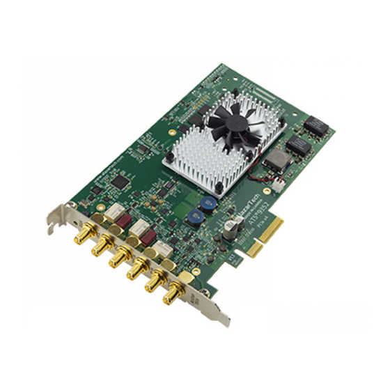
Copyright © 2020 Alazar Technologies Inc. Physical Overview Figure 1 - ATS9353 Overview ATS9353 has 6 SMA connectors: • ECLK: The external clock input • CH A: The channel A input • CH B: The channel B input • TRIG IN: The external trigger input •... - Page 51 Copyright © 2020 Alazar Technologies Inc. Figure 2 - ATS9353 Mechanical Drawing ATS9353 User Manual...
-
Page 52: Status Leds
Copyright © 2020 Alazar Technologies Inc. Status LEDs ATS9353 has 11 Status LEDs. Descriptions are provided below in the order in which they appear, from left to right: Figure 3 - ATS9353 Status LEDs • LED2 (PS3): Power Monitor error output from the board. This LED being red indicates that there is an overheating or power supply issue. - Page 53 If the test is completed successfully, this LED is turned on, otherwise it remains off. If this LED is off, there is a hardware problem with the ATS9353. • BUSY (LED12): This LED being on indicates that the board has been armed for capture.
- Page 54 Note: for Power Monitor error outputs, the Status LED remains on even after the issue is resolved. To turn off the Status LED, you must press the “Clear Int.” button in the AlazarDSO Power Monitor plug-in or restart the computer. ATS9353 User Manual...
-
Page 55: Signal Connections
Use the TRIG IN input for an external trigger only; data on the TRIG channel cannot be digitized. Use the ECLK input for clocking the ATS9353 in applications that require an external clock. Signal levels are specified in detail in Appendix A - Specifications. -
Page 56: Analog Input
For accurate measurements, make sure the signal being measured is referenced to the same ground as your ATS9353 by attaching the cable’s ground shield to the signal ground. The External Trigger input (labeled TRIG IN) either has a fixed input range of ±3 V with 50 Ω... - Page 57 The ATS9353 and ATS9351 function very similarly. The main differences between the ATS9353 and ATS9351 are: • PCIe interface: ATS9353 has a 1.6 GB/s 4-lane PCI Express Gen 2 interface whereas the ATS9351 has a 1.6 GB/s 8-lane PCI Express Gen 1 interface.
- Page 58 Copyright © 2020 Alazar Technologies Inc. Multiple Record Acquisition The ATS9353 allows the capture of multiple records into the on-board memory. This allows you to capture rapidly occurring triggers in OCT, ultrasound or spectroscopy applications. Note that ATS9353 allows you to acquire pre-trigger data.
-
Page 59: Calibration
However, your digitizer needs to be periodically recalibrated in order to maintain its specified accuracy. This calibration due date is listed on the CALIBRATION sticker affixed to your ATS9353 digitizer. For verification and recalibration your ATS9353 must be shipped back to the AlazarTech factory. ATS9353 User Manual... -
Page 60: External Clock
Copyright © 2020 Alazar Technologies Inc. External Clock The ATS9353 PCI Express Digitizer allows you to bypass the on-board clock oscillator and supply your ADC clock. This feature is extremely important in many RF applications in which phase measurements must be made between the inputs themselves or between the inputs and an external event. - Page 61 10 MHz Reference Clock ATS9353 allows the user to synchronize the sampling clock to an external 10 MHz reference signal. This is useful in many RF applications. Reference clock frequency must be 10 MHz ± 0.1 MHz and should have a high slew rate.
-
Page 62: Oct Ignore Bad Clock
Copyright © 2020 Alazar Technologies Inc. OCT Ignore Bad Clock AlazarTech has developed OCT Ignore Bad Clock, a technology that can effectively ignore the k-clock signal for a user-specified amount of time. This is useful in OCT applications if the k-clock falls out of specification during the return. -
Page 63: Optional Extended Warranty
Copyright © 2020 Alazar Technologies Inc. Optional Extended Warranty The ATS9353, like all AlazarTech digitizers, includes a standard one (1) year parts and labor warranty. However, customers might want to extend this warranty to further protect their product(s). Extended warranties must be purchased before expiration of the standard warranty (or before expiration of a previously purchased extended warranty). -
Page 64: Chapter 4: Specific Features
Copyright © 2020 Alazar Technologies Inc. Chapter 4: Specific Features This section contains information about features specific to AlazarTech digitizers and ATS9353 in particular. ATS9353 User Manual... -
Page 65: Streaming Data Across The Bus
Copyright © 2020 Alazar Technologies Inc. Streaming Data Across the Bus One of the most unique features of the ATS9353 is its on-board, dual-port acquisition memory, with custom Direct Memory Access (DMA), that can be used for signal storage. Data is acquired into the on-board memory before being transferred to the host PC memory. - Page 66 This requires a software handshake which is heavily dependent on the operating system response time. ATS9353 solves this problem by providing on-board memory that can act as a very deep FIFO and an advanced custom DMA engine that can stream data to PC host memory at up to 1.6 GB/s (exact rate is motherboard dependent).
- Page 67 Software still has to get involved in re-arming the hardware after every capture and again for reading the data from on-board acquisition memory. ATS9353’s proprietary AutoDMA circuitry allows the acquisition system to be re- armed by a hardware command and data transfer to be initiated by the hardware itself, thus removing virtually all “in-process”...
- Page 68 512 triggers occur in very rapid succession, even if all the on-board memory has not been used up. ATS9353 features a high-performance memory management firmware that allows much faster data throughput in Traditional mode than previous generation digitizers.
- Page 69 Continuous AutoDMA is also known as the data streaming mode. In this mode, data starts streaming across the PCI bus as soon as the ATS9353 is armed for acquisition. It is important to note that triggering is disabled in this mode.
- Page 70 Acquisition is stopped by an AbortCapture command. Continuous AutoDMA can easily acquire data to PC host memory at the maximum sustained transfer rate of the motherboard without causing an overflow. This is the recommended mode for very long signal recording. ATS9353 User Manual...
- Page 71 Triggered Streaming AutoDMA can easily acquire data to PC host memory at the maximum sustained transfer rate of the motherboard without causing an overflow. This is the recommended mode for RF signal recording that has to be started at a specific time, e.g. based on a GPS pulse. ATS9353 User Manual...
-
Page 72: Stream To Memory
RAM of the computer. This module is accessed by clicking on Tools >> Stream To Memory… ATS9353 User Manual... -
Page 73: Triggering
External Trigger input. While most oscilloscopes offer only one trigger engine, ATS9353 offers two trigger engines (called Engines J and K). The user can specify the number of records to capture in an acquisition, the length of each record and the amount of pre-trigger data. -
Page 74: Appendix A - Specifications
Copyright © 2020 Alazar Technologies Inc. Appendix A - Specifications This appendix lists the specifications of the ATS9353. These specifications are typical at 25 °C unless otherwise stated. The operating temperature range is 0 to 55 °C. Minimum Requirements Windows 10, Windows 8.x, Windows 7 SP1 with security... - Page 75 Input impedance 50 Ω ±1% Input protection CH A, CH B ±1 V (DC + peak AC without external attenuation) TRIG IN ±4 V (DC + peak AC without external attenuation) AUX I/O -0.7 V to +5.5 V ATS9353 User Manual...
- Page 76 500 MS/s, 250 MS/s, 100 MS/s, 50 MS/s, 20 MS/s, 10 MS/s, 5 MS/s, 2 MS/s, 1 MS/s, 500 KS/s, 200 KS/s, 100 KS/s, 50 KS/s, 20 KS/s, 10 KS/s, 5 KS/s, 2 KS/s, 1 KS/s Internal clock accuracy ±2 ppm ATS9353 User Manual...
- Page 77 Copyright © 2020 Alazar Technologies Inc. Dynamic Parameters Typical values measured on the 400 mV range of CH A of a randomly selected ATS9353. Input signal was provided by a Rohde & Schwarz SMB100A signal generator, followed by a 9-pole, 10 MHz band-pass filter (TTE Q36T-10M-1M-50-720BMF). Input frequency was set at 9.9 MHz and output amplitude was 270 mV rms, which was approximately 95% of the...
- Page 78 Software-selectable from 0 to 9,999,999 sampling clock cycles. Must meet alignment requirements (see ATS-SDK Guide for more information) Trigger timeout Software-selectable with a 10 μs resolution. Maximum settable value is 3,600 seconds. Can also be disabled to wait indefinitely for a trigger event. ATS9353 User Manual...
- Page 79 Divide-by-4 clock (dual channel mode) or divide-by-8 clock (single channel mode) Input: Amplitude 3.3 Volt TTL (5 Volt compliant) Input coupling: Certification and Compliances RoHS 3 (Directive 2015/863/EU) Compliance CE Marking — EC Conformity FCC Part 15 Class A / ICES-003 Class A Compliance ATS9353 User Manual...
- Page 80 One ATS9353 PCI Express Card † One ATS9353 Install Disk on USB flash drive † Applicable to ATS9353-001 only. USB flash drive is not provided for OEM-quantity orders (p/n ATS9353-110, ATS9353-125, ATS9353-150, ATS9353-200). For OEM- quantity orders, software must be downloaded from www.alazartech.com/Support/Downloads.
-
Page 81: Appendix B - Benchmarks
Given the constantly changing nature of computers, these benchmarks are provided as a reference only and AlazarTech assumes no liability in case the computer you purchase behaves differently than what was observed in AlazarTech’s laboratory. - Page 82 ALAZAR TECHNOLOGIES INC. 6600 Trans-Canada Highway Suite 310 Pointe-Claire, QC CANADA H9R 4S2 Tel: (514) 426-4899 Fax: (514) 426-2723 E-mail: sales@alazartech.com Web: www.alazartech.com...
Need help?
Do you have a question about the ATS9353 and is the answer not in the manual?
Questions and answers