Table of Contents
Advertisement
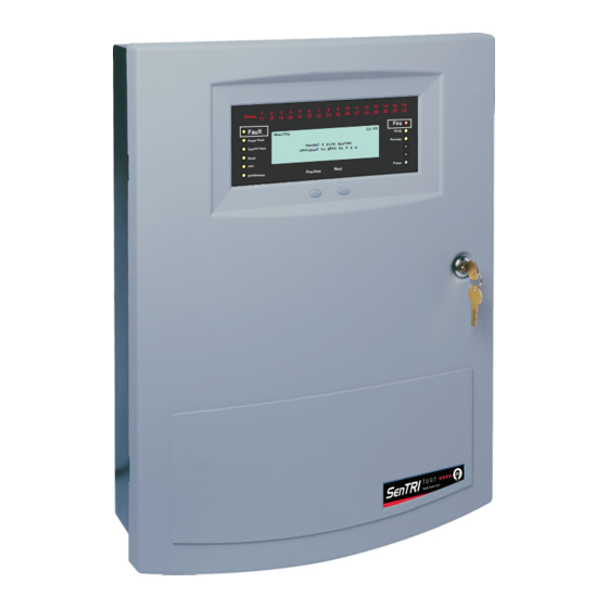
Installation instructions
based Fire detection and alarm system
7
6
4
5
3
1
2
21 22 23 24
Zon es
17 18 19 20
Fau lt
Hea lth y
Power Fault
SenT RI 4 Fire Syst
Desi gned to EN54
System Fault
Delay
Test
Pre viou s
Disabl ement
SenTRI4 Control panel
14 15 16
10 11 12 13
8
9
29 30 30 32
25 26 27 28
Fire
15:4 5
Verify
Sound er
em
Pt 2 & 4
Power
Next
f o u r
0XX XX
2 & 4
Pa rts
EN 54
Advertisement
Table of Contents

Related Manuals for SMS SenTRI4

Summary of Contents for SMS SenTRI4
- Page 1 Installation instructions SenTRI4 Control panel based Fire detection and alarm system 14 15 16 10 11 12 13 29 30 30 32 25 26 27 28 21 22 23 24 Zon es 17 18 19 20 Fire 15:4 5 Fau lt...
-
Page 2: Table Of Contents
System wiring Copper Network Cable separation Network connections Lightning protection Network wiring Cables for a SENTRI4 system Network cable screen continuity Cable for wiring Mains Supply How to minimise cross talk Cable for wiring system equipment Domain Bridge across Networks... -
Page 3: Preface
Preface Conventions This is the second issue of the Installation This is a note to highlight instructions for the SENTRI4 panel having important text that is the enhanced loop capabilities. This normally hidden in the issue contains explanation of symbols on main text. -
Page 4: Notes
Installation Notes As fitted drawings The installer should acquire site specific The power-up of the control panel information from the interested parties, and commissioning of the system is for details on the location of products done by the Servicing organisation. for installation. -
Page 5: Earth Continuity
SenTRI4 fire system Earth continuity Local Manual Call Point All earth connection points should To comply with the requirements of be clean to provide a good electrical EN54-2 : 1997 a conventional manual call conductivity path. To maintain the earth... -
Page 6: En54 Information
Local Manual Call Point EN54 information Optional functions with requirements of European standard The Control panel complies with the requirements of EN54-2 : 1997. In addition to the basic requirements of the standard the panel conforms to the following optional clauses: Clause Description... -
Page 7: System Wiring
SenTRI4 fire system System wiring If instructed, the installer may need to terminate as well as connect the cables to the appropriate terminal blocks. Cable separation Where the outgoing and return cables of a loop circuit covers more than the equivalent of one zone they must not run together, for example, either close to the Control Panel or in a service duct. -
Page 8: Cables For A Sentri4 System
Cable for wiring Mains Supply Cables for a SENTRI4 system The British Standard BS 5839 Part 1 : 2017 Code of practice for system design, installation, commissioning and maintenance states the requirements for standard and fire resisting cables in Clause 26.2 sections d & e. -
Page 9: Loop Cables
SenTRI4 fire system Enhanced loop cables Loop cables Approved cables for loop wiring There is a maximum limit (EMC Compliant) of 2Km loop cable usage Draka Firetuf FT120 Enhanced - † allowed per loop circuit. FTPLUS2EH1.5RD This maximum limit is the... -
Page 10: Network Cables
Network cables Prysmian (formally Pirelli) FP Plus* † 1.2Km maximum Panel to Panel or Panel to Network node cable distance The cables marked * utilise 3 Cores each having 1.5mm cross laminated aluminium tape with a section area tinned drain wire for electrostatic screening. - Page 11 SenTRI4 fire system Belden TR No. 89729 Prysmian (formally Pirelli) † † FP200 Flex* (Teflon jacketed) 1.2Km maximum Panel to Panel or 800m maximum Panel to Panel or Panel to Network node cable distance Panel to Network node cable distance 2 twisted pairs 3 Cores, each having 1.5mm...
-
Page 12: Loop Circuit Design
Loop Card The panel is supplied with one Post Sept 2014 enhanced Loop Card (SENTRI4-LPC-EN). If more than one loop is required then acquire additional cards for each additional loop for installation in card slot. Condition of use of Loop Card Up to 2Km loop length is possible with Sensor Sounder Strobe and Sounder †... -
Page 13: Battery Standby And Loop Load Calculator Tool
There can be up to 200 devices on a loop cable of up to 2Km when using Loop Card (SENTRI4-LPC-EN), where both device count and cable length are dictated by the number of alarm devices on the loop and how they are positioned, distributed or lumped together. -
Page 14: Typical Sentri4 System
Loop Card Typical SENTRI4 System The loop allows wiring of addressable devices like fire sensors, alarm sounders, call points, interface units, mimic and repeat panels, a combined maximum of up to 200 devices are allowed per loop circuit, a further limit on a loop circuit is determined by device loading. -
Page 15: Sentri4 Panel
SenTRI4 fire system SENTRI4 panel Features Analogue addressable fire detection † and alarm control Supports up to four loop circuits per † panel 14 15 16 10 11 12 13 29 30 30 32 25 26 27 28 21 22 23 24... -
Page 16: Technical Data
Technical data Technical data The SENTRI4 Control panel based system design has been carried out in accordance with a quality management system, which incorporates a set of rules for the design of all elements of the control and indicating equipment. The components of the... - Page 17 SenTRI4 fire system Plug in Card slots MCC / LCC -P1 Master Control card - supplied IOC / N/W -P2 Input Output card / Network card Loop 1 - P3 Loop card - supplied Loop 2 - P4 Loop card option...
-
Page 18: Batteries
2 x Powersonic 12V 21Ahr - (supplied) Model number PG12V21 B Temperature monitoring Inside the SENTRI4 panel for automatic adjustment of battery charge voltage with change in temperature. Always use the recommended replacement batteries, as there is a risk of an explosion if incorrect battery is used. Dispose of used batteries according to the manufacturer’s instructions. - Page 19 UVLO -> 20.7V ± 0.4V *max a - Max loop current 27mA x 4 = 108mA quiescent for SENTRI4 panel Primary DC Output Voltage 43V ± 5% ripple Voltage (peak to peak) <1% Hazardous voltages may still be present even when the indicators...
-
Page 20: Panel Installation
Panel installation Panel installation A SENTRI4 panel include the following parts: Back box assembly with PSU to power the Control panel † Inner door † Moulded outer door † Loop Card (1- loop card supplied), can accommodate up to 4 maximum †... -
Page 21: Mounting & Cable Entry Points
390mm Floor level a. Identify the package SENTRI4 and check that it contains all the parts. b. Remove the temporary cover from the Back box if used. c. Knock out/in the required cable entry points from the Control panel back box. -
Page 22: Semi-Flush Fixing The Control Panel
Semi-Flush fixing the control panel The fixings must support a fully assembled Control panel. The SENTRI4 panel with batteries weigh 22.2Kg. e. Stick the adhesive backed foam pad supplied to cover gaps around the centre key- hole fixing point in the back box. This is done to seal any gaps to prevent ingress. -
Page 23: Cable Termination On Enclosure
SenTRI4 fire system Cable termination on enclosure MICC Softskin (Fire Tuf) CABLE TERMINATION CABLE TERMINATION MICC CABLE MICC CABLE EARTH DRAIN Softskin Cable GLAND GLAND WIRE Should not ZINC PLATED ZINC PLATED be more than GLAND GLAND LOCK WASHER LOCK WASHER... -
Page 24: Mains Supply
Mains supply Mains supply Ensure that the mains supply cable enters the panel through a dedicated cable entry point. These fire alarm system products are NOT designed to be powered from IT Power systems. All mains powered equipment must be earthed. The mains supply to the control panel must be via an unswitched 5A fused spur unit. -
Page 25: Terminals For External Circuits
SenTRI4 fire system Terminals for external circuits The Terminal card holds all the terminals for the connection of external circuits. The exceptions are: terminals for CARDS in slots P7 and P8, these are located on the Backplane † terminals for mains supply, these are located on PSU †... -
Page 26: Device Loop Circuits
Device loop circuits Device loop circuits Upto 4 loop circuits can each accept the connection of compatible addressable devices / outstations communicating on 3217 protocol. Where a maximum of up to 200 devices / outstations are allowed per loop circuit. To maintain earth continuity on a loop, the loop cable screen must be continued through each system device, whether the earth is connected to a device or not. -
Page 27: Master Alarm Circuits
SenTRI4 fire system Master alarm circuits The two master alarm circuits accept the connection of conventional alarm sounders, such as the conventional Sounder-Strobe products. 22K Ohms - End-of-line resistor fitted in the last alarm sounder Conventional alarm sounders MA1+ MA1- MA2+ MA2-... -
Page 28: Auxiliary Relay Circuits
Auxiliary relay circuits Auxiliary relay circuits The control panel operates the auxiliary contacts when the configured event is received from the system. The auxiliary relays 1 and 2 contacts can be used to control external equipment, such as an automatic dialer that makes the call for fire fighting action. The relays can be individually re-configured to operate with either fire, fault or disablement event in the system. -
Page 29: Rs232 / Rs485 Communication
SenTRI4 fire system RS232 / RS485 Communication The control panel offers RS232 and RS485 communication via the IO card. A standard IO card (not supplied) must be inserted in slot P2 of the backplane of the panel, which facilitate RS232 and RS485 communication via terminal block P4 on Terminal card. -
Page 30: Wiring A Remote Printer
An IO card (not supplied) must be inserted in slot 2 of the backplane of the panel, which will facilitate remote printer functionality. When a remote printer is connected to a standalone SENTRI4 panel, it will print local system events. 9-way D-type connector... -
Page 31: Copper Network
SenTRI4 fire system Copper Network It is possible to network together up to 31 SenTRI Control panels, each fitted with a network card for network connections. The Network card permits communication between other control panels. The cable distance between panels and nodes can be up to 1.2Km maximum. -
Page 32: Network Connections
Network connections Network connections N/C - No connection Cable screen 0V1 +VE1 -VE1 0V2 N/C +VE2 -VE2 N/C 0V1 +VE1 -VE1 0V2 N/C +VE2 -VE2 N/C Connections for Connections for Network card in Network card in Socket P8 (Card 6) Socket P8 (Card 6) (post 08-2006) BACKPLANE... -
Page 33: Network Cable Screen Continuity
SenTRI4 fire system Network cable screen continuity NOTE: The cable screens are not connected to earth the joint or at Panel 2. Screen continuity Panel Earth connection at the joint THE JOINT Panel 1 Panel 2 These split cables MUST BE of the same type. -
Page 34: Domain Bridge Across Networks
How to minimise cross talk Domain Bridge across Networks It is possible to connect two or more SENTRI networks together by means of domain bridge. To domain bridge two or more networks a Domain bridge IO card must be installed in the bridging node / panel. There are various methods of domain bridging depending on the distances between node / panel. -
Page 35: Rs232 Domain Bridge Using Domain Io Card
SenTRI4 fire system RS232 Domain bridge using Domain IO card DOMAIN 14 15 16 10 11 12 13 29 30 30 32 21 22 23 24 25 26 27 28 Zones 17 18 19 20 Fire Fault 15:45 10 11 12 13... -
Page 36: Sentri Sensors
On completion of wiring installation SenTRI Sensors This following is short information on the SenTRI Sensor product range. The SenTRI product integrates smoke, heat with electronic sounder and LED flasher in one assembly. Full information on SenTRI Devices can be downloaded from www.smstoolbox.co.uk by registered users. -
Page 37: Siting
SenTRI4 fire system Siting A SenTRI Sensor device plugs into a dedicated SenTRI Base that is installed in the protected premises. The SenTRI Bases should be sited in locations as defined by the project plans and by BS 5839 : Part 1 : 2017. -
Page 38: Metal Back Box
Metal back box Metal back box A metal back box must be used for surface or semi-flush mounting. The earth continuity must be maintained throughout the whole loop. The earth must be securely connected to the back box. Standard Metal Box Cable gland Loop cable Loop cable... -
Page 39: Programmable Input/Output
SenTRI4 fire system Programmable input/output All SenTRI Sensor devices can be configured as either monitored input or unmonitored output. The factory setting of the programmable input / output is set as an unmonitored output, to drive an external repeat LED without a series resistor. There is a maximum cable length limit of 15 metres from the SenTRI base to the external I/O Unit. -
Page 40: Tools For Sentri Sensor
Tools for SenTRI Sensor To fit a dust cover Tools for SenTRI Sensor Place the dust cover onto the tool inside An extractor tool allows removal and the cradle. Offer the cover to the SenTRI fitting of the SenTRI Sensor device Sensor, locate and push to fit it onto the head into the Base. -
Page 41: Sentri4 Panel And Sensors Parts
SenTRI4 fire system SenTRI4 Panel and Sensors parts This section lists parts associated with the SenTRI4 panel based system. For further information on the availability of these parts contact your supplier. Control Panel SENTRI4 SENTRI4 EN54 Control panel with printer (24 hour standby) - Page 42 SenTRI - Sensors Notes...
- Page 43 SenTRI4 fire system Notes...
- Page 44 0832 SMS by Honeywell (Novar Systems Limited) Manufactured by: Honeywell Gent (Novar Systems Limited), 140 Waterside Road, Hamilton Industrial Park, Leicester, LE5 1TN, United Kingdom Product No. 031-CPR-2013 SENTRI4 EN54-2: 1997 + A1:2006, EN54-4: 1997 + A1: 2002 + A2: 2006 SENTRI4 (EN54-2 &...
Need help?
Do you have a question about the SenTRI4 and is the answer not in the manual?
Questions and answers