Table of Contents
Advertisement
Quick Links
Advertisement
Table of Contents

Related Manuals for EUCHNER CES-AR-AES-12

Summary of Contents for EUCHNER CES-AR-AES-12
- Page 1 Operating Instructions AR Evaluation Unit CES-AR-AES-12...
-
Page 2: Table Of Contents
Operating Instructions AR Evaluation Unit CES-AR-AES-12 Contents About this document ..................... 4 1.1. Scope ............................4 1.2. Target group ..........................4 1.3. Key to symbols ..........................4 1.4. Supplementary documents ......................4 Correct use ......................5 Exclusion of liability and warranty ................. 6 Description of the safety function ................7 General safety precautions ................... - Page 3 Operating Instructions AR Evaluation Unit CES-AR-AES-12 Inspection and service ..................21 Service ......................21 Declaration of conformity ................... 22 2098221-06-08/20 (Translation of the original operating instructions)
-
Page 4: About This Document
AR Evaluation Unit CES-AR-AES-12 1. About this document 1.1. Scope These operating instructions are valid for AR evaluation unit CES-AR-AES-12. These operating instructions, the document Safety information and any enclosed data sheet form the complete user information for your device. 1.2. Target group Design engineers and installation planners for safety devices on machines, as well as setup and servicing staff possessing special expertise in handling safety components. -
Page 5: Correct Use
A maximum of 12 safety switches in an AR switch chain can be connected to the AR evaluation unit CES-AR-AES-12. However, at least 2 switches must be connected. Unicode and multicode version switches can be connected. Unicode and multicode versions can be combined in an AR switch chain. -
Page 6: Exclusion Of Liability And Warranty
Operating Instructions AR Evaluation Unit CES-AR-AES-12 Table 1: Possible combinations for CES components Actuator Evaluation unit Safety switch CES-AR-C01... from V1.1.2 (see type label on the device) CES-AR-CR2... from V1.1.2 (see type label on the device) CES-AR-CL2... from V1.1.2 (see type label on the device) CES-I-.-AR-C04... -
Page 7: Description Of The Safety Function
Alternatively, the simplified method according to section 6.3 of EN 13849-1:2015 can be used for calculation. The AR switch chain subsystem, in combination with evaluation unit CES-AR-AES-12, complies with PL e, category 4 according to EN 13849-1. 2098221-06-08/20 (Translation of the original operating instructions) -
Page 8: General Safety Precautions
Operating Instructions AR Evaluation Unit CES-AR-AES-12 5. General safety precautions Safety switches fulfill personnel protection functions. Incorrect installation or tampering can lead to fatal injuries to personnel. Check the safe function of the safeguard particularly Ì after any setup work Ì... -
Page 9: Function
Operating Instructions AR Evaluation Unit CES-AR-AES-12 6. Function The AR evaluation unit is used to evaluate the individual safety switches in an AR switch chain and to reliably interrupt a safety circuit. The switching states of the connected safety switches can be signaled by means of monitoring outputs. -
Page 10: Electrical Connection
Operating Instructions AR Evaluation Unit CES-AR-AES-12 8. Electrical connection WARNING In the event of a fault, loss of the safety function due to incorrect connection. Ì Monitoring outputs must not be used as safety outputs. Ì Lay the connecting cables with protection to prevent the risk of short circuits. -
Page 11: Power Supply
Operating Instructions AR Evaluation Unit CES-AR-AES-12 8.3. Power supply The power supply of DC 24 V is supplied to the AR evaluation unit. The AR switch chain must be supplied with DC 24 V by the AR evaluation unit. +24 V... -
Page 12: Starting Behavior
Operating Instructions AR Evaluation Unit CES-AR-AES-12 8.5. Starting behavior The AR evaluation unit can be put into operation either using the autostart mode or by starting it manually. Important! If the configuration for the starting behavior is changed during operation (e.g. jumper removed), this change will be detected by the unit. -
Page 13: Connecting Safety Contacts And Feedback Loop
Operating Instructions AR Evaluation Unit CES-AR-AES-12 8.6. Connecting safety contacts and feedback loop Important! If you do not connect the feedback loop, the downstream devices will not be monitored. This situation will affect the safety category of your system. The unit has four redundant, positively driven safety contacts that switch off immediately if the actuator is removed at one of the connected safety switches or if a fault occurs. -
Page 14: Connecting Monitoring Outputs Of The Ar Evaluation Unit
Operating Instructions AR Evaluation Unit CES-AR-AES-12 The following conditions must be met for the safety contacts to be closed: For manual start Ì The feedback loop is closed Ì The start button has been pressed and released (switches on falling edge) Ì... -
Page 15: Connection Example
Operating Instructions AR Evaluation Unit CES-AR-AES-12 8.8. Connection example Safety Output Safety Output - S18 LED1 X2:4 X2:5 X2:3 X1:2 X1:8 X1:6 X1:1 Safety Read Head Inputs Door Mon itoring Safety Safety 24 V DC Mon itoring Output Output Output... -
Page 16: Setup
Operating Instructions AR Evaluation Unit CES-AR-AES-12 9. Setup WARNING Ì Pay attention to the notes on setup and on the teach-in process in the operating instructions for the safety switch used. Ì Observe correct connection on devices with teach-in input. -
Page 17: Status Leds, Control Elements And Terminal Assignment
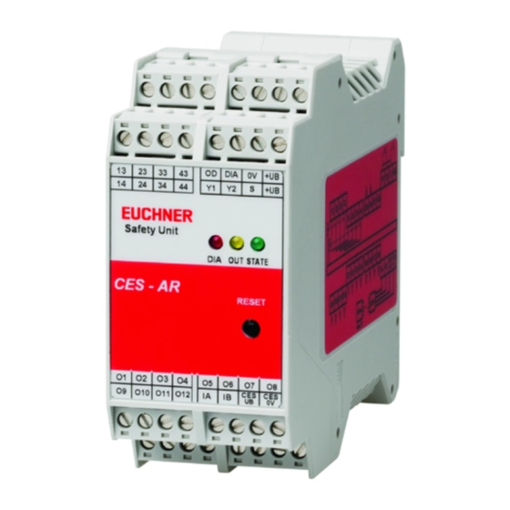
Operating Instructions AR Evaluation Unit CES-AR-AES-12 10. Status LEDs, control elements and terminal assignment The AR evaluation unit has status LEDs for the most important operating states. The significance of the individual LED states is explained in the system status table in chapter 11. -
Page 18: System Status Table
Operating Instructions AR Evaluation Unit CES-AR-AES-12 11. System status table Monitoring Indicator LEDs outputs Operating mode State 15 Hz Self-test Self-test after power-up (10 s) open Normal operation, at least one door open closed Normal operation, all doors closed Normal operation, all doors closed, start button not... -
Page 19: Technical Data
Operating Instructions AR Evaluation Unit CES-AR-AES-12 12. Technical data Value Parameter Unit min. typ. max. Housing material PA6.6 plastic Dimensions 114 x 99 x 45 Weight 0.25 Ambient temperature at U = DC 24 V °C Atmospheric humidity, not condensing... -
Page 20: Dimension Drawing
Operating Instructions AR Evaluation Unit CES-AR-AES-12 12.1. Dimension drawing EUCHNER Safety Unit DIA OUT STATE CES-AR RESET Suitable for mounting rail according to DIN 60715 12.2. System times for the AR system 12.2.1. Typical system times Ready delay: After switching on, the unit carries out a self-test for 10 s. The system is ready for operation only after this time. -
Page 21: Ordering Information And Accessories
13. Ordering information and accessories Tip! Suitable accessories, e.g. cables or assembly material, can be found at www.euchner.com. To order, enter the order number of your item in the search box and open the item view. Accessories that can be combined with the item are listed in Accessories. - Page 22 Operating Instructions AR Evaluation Unit CES-AR-AES-12 16. Declaration of conformity (Translation of the original operating instructions) 2098221-06-08/20...
- Page 23 Operating Instructions AR Evaluation Unit CES-AR-AES-12 2098221-06-08/20 (Translation of the original operating instructions)
- Page 24 Edition: 2098221-06-08/20 Title: Operating Instructions AR Evaluation Unit CES-AR-AES-12 (Translation of the original operating instructions) Copyright: © EUCHNER GmbH + Co. KG, 08/2020 Subject to technical modifications; no responsibility is accept- ed for the accuracy of this information.
Need help?
Do you have a question about the CES-AR-AES-12 and is the answer not in the manual?
Questions and answers