
Related Manuals for SCHÖLLY FIBEROPTIC FLEXILUX 200 LED

Summary of Contents for SCHÖLLY FIBEROPTIC FLEXILUX 200 LED
- Page 1 Gebrauchsanweisung FLEXILUX 200 LED Lichtquelle für die medizinische Endoskopie Instructions For Use FLEXILUX 200 LED Light Source for Medical Endoscopy...
- Page 2 TPA305-000-1208-20_H Version: H 2020 - Mar - 13 Gebrauchsanweisung | 13 - Mar - 2020 | Version: H Seite 2 von 76...
-
Page 3: Table Of Contents
Inhaltsverzeichnis Seite 0 Wichtige Hinweise zu diesem Dokument................8 Geltungsbereich, Identifikation, Zweck..................8 Zielgruppe............................8 Handhabung und Aufbewahrung des Dokuments................. 8 Ergänzende Dokumente.........................8 1 Allgemeine Informationen zum Produkt................9 Lieferumfang........................... 9 Produktbeschreibung........................9 1.2.1 Leistungsmerkmale und Funktionsweise................9 1.2.2 Übersichtsdarstellung....................... 10 1.2.3 Anschließbare Lichtleiter.................... - Page 4 3 Installation und Inbetriebnahme..................21 Sicherheitshinweise........................21 Qualifikation des Personals......................22 Installation.............................23 3.3.1 Aufstellung........................23 3.3.2 Netzanschluss........................24 Inbetriebnahme..........................25 3.4.1 Erste Inbetriebnahme und Funktionsprüfung..............25 4 Bedienung..........................26 Sicherheitshinweise........................26 Qualifikation des Personals......................27 Technische Überprüfung vor dem Gebrauch................28 4.3.1 Sichtkontrolle........................28 4.3.2 Funktionsprüfung......................28 Einschalten und Ausschalten, Trennung von der Stromversorgung..........29 Anschluss eines Lichtleiters......................
- Page 5 Content Page 0 Important Information about this Document..............43 Scope of Validity, Identification, Purpose..................43 Target Group..........................43 Using and Storing this Document....................43 Supplementary Documents......................43 1 General Information about the Device................44 Scope of Delivery......................... 44 Product Description........................44 1.2.1 Performance Characteristics and Function..............44 1.2.2...
- Page 6 3 Installation and Initial Operation..................56 Safety Notices..........................56 Staff Qualifications........................57 Installation.............................58 3.3.1 Setup..........................58 3.3.2 Connection to Mains Power.....................59 Initial Operation..........................59 3.4.1 Initial Operation and Function Check................59 4 Operation..........................60 Safety Notices..........................60 Staff Qualifications........................61 Technical Inspection Prior to Use....................62 4.3.1 Visual Inspection......................
- Page 7 Gebrauchsanweisung | 13 - Mar - 2020 | Version: H Seite 7 von 76...
-
Page 8: Wichtige Hinweise Zu Diesem Dokument
Wichtige Hinweise zu diesem Dokument Geltungsbereich, Identifikation, Zweck Diese Gebrauchsanweisung ist gültig für folgendes Produkt: Artikelbezeichnung: FLEXILUX 200 LED Artikelnummer: 05.0740LED Diese Gebrauchsanweisung ist Bestandteil des Produkts und enthält alle Informa- tionen, die Anwender und Betreiber für den sicheren und bestimmungsgemäßen Gebrauch benötigen. -
Page 9: Allgemeine Informationen Zum Produkt
1 Allgemeine Informationen zum Produkt 1.1 Lieferumfang Allgemeine Informationen zum Produkt Lieferumfang Der Lieferumfang des Produkts umfasst: Eine Lichtquelle (Art.-Nr. 05.0740LED) Ein Netzkabel (Art.-Nr. auf Anfrage) Eine Gebrauchsanweisung (TPA305-000-1208-20_H) Eine Broschüre zur EMV (TPI001-121-0803-20) Lieferumfang Kontrollieren Sie die Lieferung nach Erhalt anhand des Lieferscheins auf Vollstän- kontrollieren! digkeit und Unversehrtheit. -
Page 10: Übersichtsdarstellung
1 Allgemeine Informationen zum Produkt 1.2 Produktbeschreibung Im Fall eines Temperaturanstiegs im Gerät, etwa bei dauerhaft überhöhter Um- Überhitzungsschutz gebungstemperatur, zeigt das Display einen Warnhinweis an. Die gerätein- terne Kühlung kann den Temperaturanstieg für ca. eine Stunde kompensie- ren, dann schaltet sich das Gerät zur Vermeidung von Schäden ab (siehe auch Abschnitt 2.2.5 Störungsanzeigen). -
Page 11: Anschließbare Lichtleiter
1 Allgemeine Informationen zum Produkt 1.2 Produktbeschreibung Rückansicht Abbildung 1-2: Rückansicht der Lichtquelle. Sicherungshalter Anschluss für Netzkabel Hauptschalter für Stromversorgung Potentialausgleichsanschluss Anschlussbuchsen für den MIS-Bus Schnittstelle für Service (verblendet) 1.2.3 Anschließbare Lichtleiter Das Produkt ist mit Kaltlichtkabeln und Hochleistungslichtleitern von Karl Storz, Richard Wolf und Olympus sowie firmeneigenen Lichtleitern kompatibel: Faserbündel von 3,5 bis 4,8 mm Ø... -
Page 12: Verwendungszweck
1 Allgemeine Informationen zum Produkt 1.3 Verwendungszweck Verwendungszweck 1.3.1 Zweckbestimmung Die Lichtquelle ist für den Einsatz in der humanmedizinischen Endoskopie be- stimmt. Sie dient in Verbindung mit Lichtleiter, Endoskop und Kamera zur Aus- leuchtung des menschlichen Körperinneren. Das Produkt erfüllt in Verbindung mit einem geeigneten Lichtleiter die BF-Bedin- gungen gemäß... -
Page 13: Kennzeichnung
1 Allgemeine Informationen zum Produkt 1.5 Kennzeichnung Kennzeichnung 1.5.1 Piktogramme und Angaben auf Produkt und Verpackung Nachfolgend sind die Piktogramme erklärt, die Sie auf dem Produkt oder der Ver- packung finden. Gebrauchsanweisung befolgen CE-Kennzeichnung Artikelnummer Seriennummer Medizinprodukt Hersteller Herstellungsdatum Vorsicht (IEC 60601-1 3rd edition) / Achtung, Begleitpapiere beachten (IEC 60601-1 2nd edition) Nicht zum Einsatz in Magnetresonanz-Umgebung Anwendungsteil des Typs BF gemäß... -
Page 14: Piktogramme In Diesem Dokument
1 Allgemeine Informationen zum Produkt 1.5 Kennzeichnung Getrennte Sammlung von Elektro- und Elektronik-Altgeräten Elektrische Sicherung Wechselstrom Erhöhte Temperatur 1.5.2 Piktogramme in diesem Dokument Nachfolgend sind die Piktogramme erklärt, die Sie in diesem Dokument finden. Allgemeines Warnzeichen Warnung vor gefährlicher elektrischer Spannung Warnung vor Biogefährdung, Infektionsgefahr Kontakt zum technischen Service Wenden Sie sich bei Fragen zu unseren Produkten, zur Installation oder zum Ge-... -
Page 15: Allgemeine Sicherheitsinformationen
2 Allgemeine Sicherheitsinformationen 2.1 Darstellung von Warnhinweisen Allgemeine Sicherheitsinformationen Darstellung von Warnhinweisen 2.1.1 Warnhinweise zu Beginn eines Kapitels Die nachfolgend beschriebenen Warnhinweise finden Sie gesammelt am Anfang von Kapiteln, deren Handlungsanleitungen entsprechende Gefahren bergen kön- nen. Die Schwere der potentiellen Gefahr drückt sich im Signalwort aus, das den Warnhinweis anführt. -
Page 16: Warnhinweise Im Text
2 Allgemeine Sicherheitsinformationen 2.1 Darstellung von Warnhinweisen 2.1.2 Warnhinweise im Text Die nachfolgend beschriebenen Warnhinweise finden Sie in Handlungsanleitun- gen unmittelbar vor Handlungsschritten, deren Durchführung Gefahren bergen kann. Die Schwere der potentiellen Gefahr drückt sich im Signalwort aus, das den Warnhinweis anführt. -
Page 17: Qualifikation Des Personals
2 Allgemeine Sicherheitsinformationen 2.2 Produktsicherheit WARNUNG! Gefahr durch eigenmächtige Änderungen am Produkt. Personen können schwer verletzt werden. Nehmen Sie keinerlei eigenmächtige Änderun- gen vor. WARNUNG! Betrieb des geöffneten Geräts. Gefahr des elektrischen Schlags. Gerät nicht öffnen. Gerät nur im geschlossenen Zustand betreiben. WARNUNG! Ausfall von Komponenten während eines Eingriffs. -
Page 18: Elektromagnetische Verträglichkeit
2 Allgemeine Sicherheitsinformationen 2.2 Produktsicherheit 2.2.3 Elektromagnetische Verträglichkeit Medizinische elektrische Geräte unterliegen erhöhten Anforderungen in Bezug auf ihre elektromagnetische Verträglichkeit (EMV). Trotz der hohen Störfestigkeit und der geringen Störaussendung des Geräts be- stehen Anforderungen an die Installation und den Aufstellort des Geräts und an die räumlichen Umgebungsbedingungen hinsichtlich der EMV. -
Page 19: Kombination Mit Medizinischen Elektrischen Geräten
2 Allgemeine Sicherheitsinformationen 2.2 Produktsicherheit 2.2.4 Kombination mit medizinischen elektrischen Geräten Das Produkt ist mit Komponenten anderer Hersteller kombinierbar, sofern alle Komponenten die Anforderungen der IEC 60601-1 an die Sicherheit von medizini- schen elektrischen Geräten erfüllen. Der Betreiber steht in der Verantwortung, die Funktionsfähigkeit des Systems zu prüfen, sicherzustellen und zu erhalten. - Page 20 2 Allgemeine Sicherheitsinformationen 2.2 Produktsicherheit Ausfall des Gehäuselüfters Im Falle eines Ausfalls des Gehäuselüfters erscheint folgende Anzeige im Dis- play: Abbildung 2-3: Displayanzeige bei Ausfall des Gehäuselüfters. Bei einem Ausfall des Gehäuselüfters steigt die Temperatur im Innern des Geräts in Abhängigkeit von der Umgebungstemperatur an. Bei hoher Umgebungstempe- ratur könnte es nach 30-45 Minuten zur Überhitzung im Gerät kommen.
-
Page 21: Installation Und Inbetriebnahme
3 Installation und Inbetriebnahme 3.1 Sicherheitshinweise Installation und Inbetriebnahme Sicherheitshinweise WARNUNG Unsachgemäße elektrische Installation Gefahr von Brand, Kurzschluss oder elektrischem Schlag Sicherstellen, dass die elektrische Installation den national geltenden tech- nischen Vorschriften entspricht WARNUNG Installation eines medizinischen elektrischen Systems Gefahr von Brand, Kurzschluss oder elektrischem Schlag Durchführung der Installation nur durch qualifiziertes Personal Bei der Kombination von elektrischen Geräten IEC 60601-1 befolgen Nicht-medizinische Geräte, die die anwendbaren IEC-Sicherheitsnormen... -
Page 22: Qualifikation Des Personals
3 Installation und Inbetriebnahme 3.1 Sicherheitshinweise WARNUNG Verwendung von Mehrfachsteckdosen Gefahr von Brand, Kurzschluss, elektrischem Schlag, vermindertem Sicher- heitsgrad Mehrfachsteckdosen nach Möglichkeit vermeiden Falls benötigt, medizinisch zugelassene Mehrfachsteckdosen verwenden Mehrfachsteckdosen niemals hintereinanderschalten Mehrfachsteckdosen nicht abdecken (Wärmestau) Mehrfachsteckdosen nicht auf den Boden legen Zugentlastung verwenden Nur Geräte an eine gemeinsame Mehrfachsteckdose anschließen, die als Teil des medizinischen elektrischen Systems bestimmt sind... -
Page 23: Installation
3 Installation und Inbetriebnahme 3.3 Installation Installation 3.3.1 Aufstellung Gerät aufstellen Beachten Sie die Sicherheitshinweise am Anfang dieses Kapitels und die beilie- gende Broschüre zur EMV. Gehen Sie so vor: WARNUNG! Gefahr durch Aufstellung im explosionsgefährdeten Bereich. Er- höhte Brand- und Explosionsgefahr in sauerstoffangereicherter Umgebung. Gerät außerhalb des explosionsgefährdeten Bereichs und nicht in der Nähe entflammbarer Stoffe aufstellen. -
Page 24: Netzanschluss
3 Installation und Inbetriebnahme 3.3 Installation 3. Wenn Sie die Lichtquelle mit den Kamerakopf-Tasten steuern wollen, verbinden Sie die Kamera mit der Lichtquelle an einer der Anschlussbuchsen mit der Aufschrift MIS-BUS. Beachten Sie hierzu die Gebrauchsanweisung der Kamera. Das Gerät ist ordnungsgemäß aufgestellt. 3.3.2 Netzanschluss Gerät anschließen... -
Page 25: Inbetriebnahme
3 Installation und Inbetriebnahme 3.4 Inbetriebnahme Inbetriebnahme 3.4.1 Erste Inbetriebnahme und Funktionsprüfung Funktionsprüfung durchführen Bei der ersten Inbetriebnahme überprüfen Sie die Installation und stellen die Funktionsfähigkeit des Geräts fest. Voraussetzung: Die Installation muss abgeschlossen sein. Gehen Sie so vor: 1. Stellen Sie den Hauptschalter auf der Geräterückseite auf EIN. Das Gerät wechselt in den Standby-Modus, der EIN/Standby-Taster an der Frontseite leuchtet grün. -
Page 26: Bedienung
4 Bedienung 4.1 Sicherheitshinweise Bedienung Sicherheitshinweise WARNUNG Änderungen an der Installation Gefahr von Brand, Kurzschluss und elektrischem Schlag Sicherheitshinweise im Kapitel Installation und Inbetriebnahme beachten Installation nicht eigenmächtig verändern Wenn eine Mehrfachsteckdose in der Installation enthalten ist, nicht eigen- mächtig zusätzliche Geräte anschließen Mehrfachsteckdosen niemals hintereinanderschalten WARNUNG Ableitstrom bei Berührung des Patienten... -
Page 27: Qualifikation Des Personals
4 Bedienung 4.1 Sicherheitshinweise WARNUNG Wechselwirkungen mit gleichzeitig verwendeten Geräten (z. B. Laser, HF- Chirurgie) Gefährdung von Patient und Anwender, Bildstörungen, Beschädigung des Pro- dukts Sicherstellen, dass alle verwendeten Geräte mindestens die geforderten BF-Bedingungen bzw. CF-Bedingungen gemäß IEC 60601-1 erfüllen Kennzeichnung und Gebrauchsanweisung der verwendeten Geräte beach- Direkten Kontakt des Endoskops und leitfähiger Teile mit aktivierten HF-Elektroden vermeiden... -
Page 28: Technische Überprüfung Vor Dem Gebrauch
4 Bedienung 4.3 Technische Überprüfung vor dem Gebrauch Technische Überprüfung vor dem Gebrauch 4.3.1 Sichtkontrolle Sichtkontrolle durchführen Führen Sie vor jedem Eingriff eine Sichtkontrolle durch. Gehen Sie so vor: Gehäuse 1. Stellen Sie sicher, dass das Gehäuse der Lichtquelle frei von äußeren unbeschädigt? Beschädigungen ist. -
Page 29: Einschalten Und Ausschalten, Trennung Von Der Stromversorgung
4 Bedienung 4.4 Einschalten und Ausschalten, Trennung von der Stromversorgung Einschalten und Ausschalten, Trennung von der Stromversorgung Gerät einschalten Gehen Sie so vor: 1. Schalten Sie das Gerät an der Gerätevorderseite ein. Das Gerät lässt sich nicht einschalten? Der Hauptschalter auf der Geräterückseite ist ausgeschaltet. Stellen Sie den Hauptschalter auf EIN. -
Page 30: Anschluss Eines Lichtleiters
4 Bedienung 4.5 Anschluss eines Lichtleiters Anschluss eines Lichtleiters Lichtleiter anschließen Der Multi-Lichtleiteranschluss ermöglicht Ihnen den Anschluss von Lichtleitern verschiedener Hersteller. Original-Lichtleiter von Karl Storz, Richard Wolf und Olympus können ohne Adap- ter direkt eingesteckt werden. Firmeneigene Lichtleiter sind mit entsprechenden Lichtleitkabeladaptern zu verwenden. -
Page 31: Nutzen Der Standby Led-Funktion
4 Bedienung 4.8 Nutzen der Standby LED-Funktion Nutzen der Standby LED-Funktion Standby LED-Funktion nutzen Nutzen Sie die Standby LED-Funktion, wenn Sie die Lichtzufuhr kurzfristig auf den minimalen Wert dimmen wollen. Gehen Sie so vor: 1. Um die Lichtzufuhr auf 5 % zu senken, tippen Sie auf den Standby LED-Taster. Die LED schaltet auf 5 %, das Gerät bleibt eingeschaltet. -
Page 32: Reinigung
5 Reinigung 5.1 Sicherheitshinweise Reinigung Sicherheitshinweise WARNUNG Gefahr durch unsachgemäße Reinigung Gefahr von Brand, Kurzschluss und elektrischem Schlag Vor der Reinigung Gerät am Hauptschalter auf der Geräterückseite aus- schalten und vom Stromnetz trennen Sicherstellen, dass keine Flüssigkeit in das Gerät eindringt Anschluss an das Stromnetz erst wieder nach vollständiger Trocknung ACHTUNG Unsachgemäße Reinigung... -
Page 33: Wartung Und Instandsetzung
6 Wartung und Instandsetzung 6.1 Sicherheitshinweise Wartung und Instandsetzung Sicherheitshinweise WARNUNG Gefahr durch unsachgemäße Wartung und Instandsetzung Gefahr von Brand, Kurzschluss und elektrischem Schlag Durchführung von Wartung und Instandsetzung nur durch qualifiziertes Personal Keine Änderung am Gerät vornehmen Qualifikation des Personals Fachpersonal Personal, das die Wartung oder die Sicherheitstechnische Kontrolle am Gerät vornimmt, muss über eine abgeschlossene adäquate Ausbildung verfügen und... -
Page 34: Wechsel Der Sicherung
6 Wartung und Instandsetzung 6.4 Wechsel der Sicherung Wechsel der Sicherung Sicherung wechseln Gehen Sie so vor: 1. Schalten Sie das Gerät am Hauptschalter auf der Rückseite des Geräts aus und trennen Sie es von der Stromversorgung, indem Sie den Netzstecker aus dem Netzanschluss an der Geräterückseite ziehen. -
Page 35: Reparatur
6 Wartung und Instandsetzung 6.5 Reparatur Reparatur Sollte einmal eine Reparatur des Produkts erforderlich sein, wenden Sie sich an eine unserer Niederlassungen. Die Kontaktdaten finden Sie auf der Rückseite die- ser Gebrauchsanweisung. Legen Sie der Sendung eine möglichst genaue Fehlerbeschreibung bei und ver- merken Sie im Lieferschein die Artikelnummer und die Seriennummer des Pro- dukts. -
Page 36: Vorgehen Bei Störungen, Störungstabelle
6 Wartung und Instandsetzung 6.6 Vorgehen bei Störungen, Störungstabelle Vorgehen bei Störungen, Störungstabelle Störung Mögliche Ursache Abhilfe Kein Betrieb Keine elektrische Spannung vor- Netzanschluss überprüfen und ggf. handen Netzanschluss herstellen Sicherung überprüfen und ggf. tau- schen Netzteil defekt Lichtquelle zur Reparatur einsenden Lampe leuchtet nicht Gerät überhitzt Gerät abkühlen lassen... -
Page 37: Produktdaten
7 Produktdaten 7.1 Technische Daten Produktdaten Technische Daten Abmessung (B x H x T) 295 x 130 x 355 mm Gewicht 5,8 kg Stromaufnahme 1,0 - 0,42A Netzspannung 100-240V~, 50/60Hz Schutzklasse gemäß IEC 60601-1 Schutzklasse I Gerätesicherung T1,6AL 250V Schnittstellen 2x MIS-Bus Schutzart IP X0... -
Page 38: Ersatzteile Und Zubehör
7 Produktdaten 7.3 Ersatzteile und Zubehör Ersatzteile und Zubehör Verwenden Sie nur original Ersatzteile und Zubehör. Abbildung Bezeichnung Artikelnummer Feinsicherung, T1,6AL 250V, 5x20 mm 94600. MIS-Bus-Kabel, 2,25 m A057635 MIS-Bus-Kabel, 0,75 m A059584 Netzkabel (länderspezifisch) auf Anfrage Tabelle 7-1: Ersatzteile und Zubehör. Gebrauchsanweisung | 13 - Mar - 2020 | Version: H Seite 38 von 76... - Page 39 7 Produktdaten 7.3 Ersatzteile und Zubehör Abbildung Bezeichnung Artikelnummer Hochleistungslichtleiter, 3,5 x 1.800 mm 05.0084l (Standard-Lichtleiter) Hochleistungslichtleiter, 3,5 x 2.300 mm 05.0088l (Standard-Lichtleiter) Hochleistungslichtleiter, 3,5 x 3.000 mm 05.0085l (Standard-Lichtleiter) Hochleistungslichtleiter, 4,8 x 1.800 mm 05.0086l (Standard-Lichtleiter) Hochleistungslichtleiter, 4,8 x 2.300 mm 05.0090l (Standard-Lichtleiter) Hochleistungslichtleiter,...
- Page 40 7 Produktdaten 7.3 Ersatzteile und Zubehör Abbildung Bezeichnung Artikelnummer Lichtleiter-Adapter (zum Anschluss an den Lichtleiter, lichtquellenseitig) für: System Storz 05.0100z System Wolf 05.0102b System Olympus 05.0101o Lichtleiter-Adapter (zum Anschluss an den Lichtleiter, endoskopseitig) für: Storz-Endoskope 05.0108z Wolf-Endoskope 05.0110b ACMI-Endoskope 05.0112c Lichtleiter-Adapter (zum Anschluss an das Endoskop) für: Storz-Lichtleiter 05.0114z...
-
Page 41: Entsorgung
8 Entsorgung Entsorgung WARNUNG Kontaminiertes Produkt Infektionsgefahr Produkt vor der Entsorgung aufbereiten (Kapitel 5) Beachten Sie im Zusammenhang mit Entsorgung und Recycling des Produkts und seiner Komponenten die national geltenden Vorschriften. Die Verpackung des Produkts besteht aus einer Polyethylen (PE)-Tüte mit PE- Schaumstoffeinlage (0,50 kg) sowie einem Karton aus Wellpappe (1,18 kg). - Page 42 Instructions For Use | 13 - Mar - 2020 | Version: H Page 42 of 76...
-
Page 43: Important Information About This Document
Important Information about this Document Scope of Validity, Identification, Purpose These instructions for use apply to the following product: Item name: FLEXILUX 200 LED Item number: 05.0740LED These instructions for use are an integral component of the product and contain all the information required by users and operators for safe and proper use. -
Page 44: General Information About The Device
1 General Information about the Device 1.1 Scope of Delivery General Information about the Device Scope of Delivery The scope of delivery for the device includes: one light source (item no. 05.0740LED) one power cord (item no. available on request) one set of instructions for use (TPA305-000-1208-20_H) one EMC brochure (TPI001-121-0803-20) Check scope of... -
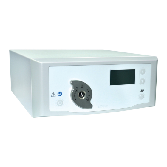
Page 45: Visual Overview
1 General Information about the Device 1.2 Product Description 1.2.2 Visual Overview Front view Figure 1-1: Front view of the light source. ON / standby button Multi-light-guide adapter Standby LED button Brightness controls Instructions For Use | 13 - Mar - 2020 | Version: H Page 45 of 76... -
Page 46: Compatible Light Guides
1 General Information about the Device 1.2 Product Description Rear view Figure 1-2: Rear view of the light source. Fuse holder Connection for power cord Main power switch Potential equalization terminal MIS-Bus ports Port for service (covered) 1.2.3 Compatible Light Guides The product is compatible with cold light guides and high-power light guides sup- plied by Karl Storz, Richard Wolf, Olympus and our own company: Fiber bundles of 3.5 to 4.8 mm Ø... -
Page 47: Usage
1 General Information about the Device 1.3 Usage Usage 1.3.1 Intended Use This light source is intended for use in endoscopy systems for human medicine. In combination with a light guide, endoscope, and camera, its purpose is to illumi- nate the inside of the human body. In combination with a suitable light guide the device meets the BF classification requirements for protection from electric shock according to IEC 60601-1 and is approved for use in combination with applied parts. -
Page 48: Marking
1 General Information about the Device 1.5 Marking Marking 1.5.1 Pictograms and Information on the Device and Packaging This section describes the different pictograms that feature on the product or packaging. Adhere to the instructions for use CE marking Item number Serial number Medical Device Manufacturer... -
Page 49: Pictograms In This Document
1 General Information about the Device 1.5 Marking Separate collection for WEEE (waste of electrical and electronic equipment) Fuse Alternating current Hot temperature 1.5.2 Pictograms in this Document This section describes the pictograms used in this document. General warning sign Dangerous electrical voltage warning sign Biohazard warning sign, risk of infection Service Department Contact Details... -
Page 50: General Safety Information
2 General Safety Information 2.1 Safety Messages in this Document General Safety Information Safety Messages in this Document 2.1.1 Safety Messages at the Start of a Chapter The safety messages described in this section will be listed at the start of any chapter containing instructions that carry a particular risk. -
Page 51: Safety Messages In The Body Of The Text
2 General Safety Information 2.1 Safety Messages in this Document 2.1.2 Safety Messages in the Body of the Text The warnings described in this section will be listed within the body of the instruc- tions directly prior to any steps that carry a particular risk. The severity of the potential risk is expressed by the signal word in the beginning of the message. -
Page 52: Staff Qualifications
2 General Safety Information 2.2 Product Safety WARNING! Risks from the arrangement, setup, combination, or properties of con- nected or surrounding devices or equipment. Follow the instructions for use of the respective devices. Perform a risk assessment. WARNING! High-intensity light source. Risk of injury to eyes. Do not look directly into the open end of the light guide. -
Page 53: Electromagnetic Compatibility
2 General Safety Information 2.2 Product Safety 2.2.3 Electromagnetic Compatibility Medical electrical equipment is subject to stringent electromagnetic compatibility (EMC) requirements. Despite the device’s high interference immunity and low emitted interference, compliance with EMC-related requirements is necessary with regard to installa- tion, installation location, and ambient conditions. -
Page 54: Combination With Medical Electrical Equipment
2 General Safety Information 2.2 Product Safety 2.2.4 Combination with Medical Electrical Equipment The device can be combined with components from other manufacturers provided that all components are compliant with the medical electrical equipment safety re- quirements according to IEC 60601-1. It is the operator’s responsibility to check and make sure that the system is and remains fully operational. - Page 55 2 General Safety Information 2.2 Product Safety Failure of housing fan If the housing fan fails, the following message is displayed: Figure 2-3: Message displayed when housing fan fails. When housing fan fails, the temperature inside the device climbs in relation to the ambient temperature.
-
Page 56: Installation And Initial Operation
3 Installation and Initial Operation 3.1 Safety Notices Installation and Initial Operation Safety Notices WARNING Electrical connections installed improperly Risk of fire, short circuit, or electric shock Make sure that the electrical connections are installed in accordance with the relevant national technical regulations WARNING Medical electrical system installation Risk of fire, short circuit, or electric shock... -
Page 57: Staff Qualifications
3 Installation and Initial Operation 3.1 Safety Notices WARNING Use of multiple sockets Risk of fire, short circuit, electrical shock, reduced level of safety Whenever possible, avoid the use of multiple sockets If required, use medically approved multiple sockets Never connect multiple sockets in series Do not cover multiple sockets (leads to heat accumulation) Do not place multiple sockets on the floor Use traction relief... -
Page 58: Installation
3 Installation and Initial Operation 3.3 Installation Installation 3.3.1 Setup Setting up the device Observe the safety notices provided at the start of this chapter and refer to the en- closed EMC brochure. Proceed as follows: WARNING! Risk from installation in potentially explosive locations. Increased risk of fire and explosion in oxygen-enriched atmospheres. -
Page 59: Connection To Mains Power
3 Installation and Initial Operation 3.3 Installation Observe the instructions for use supplied with the camera. The device is properly installed. 3.3.2 Connection to Mains Power Connecting the device to the mains Do not connect the device to the mains until you have completed all the previous activities. -
Page 60: Operation
4 Operation 4.1 Safety Notices Operation Safety Notices WARNING Modifications to the installation Risk of fire, short circuit, and electric shock Follow the safety notices in the Installation and Initial Operation chapter Do not make unauthorized changes to the installation If the installation contains a multiple socket, do not connect additional de- vices to this without authorization Never connect multiple sockets in series... -
Page 61: Staff Qualifications
4 Operation 4.1 Safety Notices WARNING Interactions between devices in simultaneous use (e.g. lasers, electro- surgery) Risk to the patient and user, image interference, damage to the device Ensure that all the devices in use meet at minimum the required type BF or type CF classification requirements according to IEC 60601-1 Observe the labeling and instructions for use of the devices used Avoid direct contact between the endoscope and conductive parts with ac-... -
Page 62: Technical Inspection Prior To Use
4 Operation 4.3 Technical Inspection Prior to Use Technical Inspection Prior to Use 4.3.1 Visual Inspection Performing a visual inspection A visual inspection must be performed prior to each medical procedure. Proceed as follows: Is the housing 1. Inspect the housing of the light source for external damage. undamaged? Do not use the light source if there is any external damage to the housing. -
Page 63: Switching On And Off, Separation From The Power Supply
4 Operation 4.4 Switching On and Off, Separation from the Power Supply Switching On and Off, Separation from the Power Supply Switching on the device Proceed as follows: 1. Switch on the device at the front. Device does not switch on? The main switch on the rear is switched off. -
Page 64: Connection Of A Light Guide
4 Operation 4.5 Connection of a Light Guide Connection of a Light Guide Connecting the light guide The multi-light-guide connector enables the connection of light guides supplied by different manufacturers. Original light guides from Karl Storz, Richard Wolf and Olympus can be attached directly without adapters. -
Page 65: Using The Led Standby Function
4 Operation 4.8 Using the LED Standby Function Using the LED Standby Function Using the LED standby function Use the LED standby function if you want to briefly dim the light to the minimum level. Proceed as follows: 1. To set the light supply at 5 %, tap the LED standby button. The LED output is reduced to 5 %;... -
Page 66: Cleaning
5 Cleaning 5.1 Safety Notices Cleaning Safety Notices WARNING Risks associated with improper cleaning Risk of fire, short circuit, and electric shock Before cleaning, switch off the device at its rear main switch and discon- nect from the mains power supply Make sure no moisture penetrates the device The device should not be reconnected to the mains power supply until it has completely dried... -
Page 67: Maintenance And Repair
6 Maintenance and Repair 6.1 Safety Notices Maintenance and Repair Safety Notices WARNING Improper maintenance and repair Risk of fire, short circuit, and electric shock All maintenance and repair work must only be performed by qualified per- sonnel Do not make any modifications to the device Staff Qualifications Qualified personnel Personnel responsible for maintaining the device or carrying out safety inspec-... -
Page 68: Changing Of The Fuse
6 Maintenance and Repair 6.4 Changing of the Fuse Changing of the Fuse Changing the fuse Proceed as follows: 1. Switch OFF the device at the main switch on the rear and pull out the power cord from the rear of the device to disconnect the power. NOTICE! Pulling the power cable will damage it. -
Page 69: Repair
6 Maintenance and Repair 6.5 Repair Repair Should you need to arrange a repair for the device, please contact one of our sub- sidiaries. Contact details can be found on the back of these instructions for use. When you send in equipment, please enclose as accurate a fault description as possible, and record the item number and serial number of the product on the de- livery note. -
Page 70: Troubleshooting Table
6 Maintenance and Repair 6.6 Troubleshooting Table Troubleshooting Table Issue Possible causes Fixes No operation No power supply Check the mains connection and connect the power if necessary Check the fuse and replace if neces- sary Malfunction in power supply unit Send the light source in for repair Light doesn’t switch on Device is overheated... -
Page 71: Product Data
7 Product Data 7.1 Technical Data Product Data Technical Data Dimensions (W x H x D) 295 x 130 x 355 mm Weight 5.8 kg Current consumption 1.0 - 0.42A Supply voltage 100-240V~, 50/60Hz Protection class acc. to IEC 60601-1 Protection class I Device fuse T1.6AL 250V... -
Page 72: Spare Parts And Accessories
7 Product Data 7.3 Spare Parts and Accessories Spare Parts and Accessories Use original spare parts and accessories only. Image Designation Item number Micro-fuse T1.6AL 250V, 5x20 mm 94600. MIS-Bus cable, 2.25 m A057635 MIS-Bus cable, 0.75 m A059584 Power cord (country-specific) on request Table 7-1: Spare parts and accessories. - Page 73 7 Product Data 7.3 Spare Parts and Accessories Image Designation Item number High-power light guide, 3.5 x 1,800 mm 05.0084l (standard light guide) High-power light guide, 3.5 x 2,300 mm 05.0088l (standard light guide) High-power light guide, 3.5 x 3,000 mm 05.0085l (standard light guide) High-power light guide,...
- Page 74 7 Product Data 7.3 Spare Parts and Accessories Image Designation Item number Light guide adapter (to connect to the light guide, light source side) for: Storz systems 05.0100z Wolf systems 05.0102b Olympus systems 05.0101o Light guide adapter (to connect to the light guide, endoscope side) for: Storz endoscopes 05.0108z Wolf endoscopes...
-
Page 75: Disposal
8 Disposal Disposal WARNING Contaminated device Risk of infection The device must be reprocessed prior to disposal (chapter 5) When disposing of or recycling the device and its components, you must adhere to the applicable national regulations governing waste disposal and recycling. The product is packed in a polyethylene (PE) bag and a PE foam inlay (0.50 kg), as well as a corrugated cardboard box (1.18 kg). - Page 76 SCHÖLLY FIBEROPTIC GMBH Robert-Bosch-Str. 1-3 79211 Denzlingen Germany...
Need help?
Do you have a question about the FLEXILUX 200 LED and is the answer not in the manual?
Questions and answers