Advertisement
Quick Links
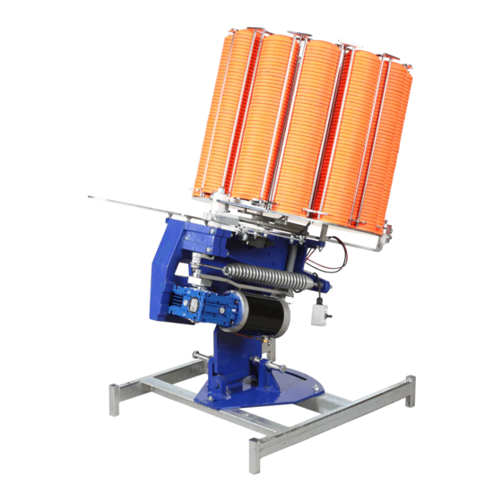
Signature ATA
MKII
Operating Instructions
WARNING
Clay target launchers can be
dangerous and must be treated
with great care at all times to
avoid accidents.
Never place any bodily part into
the path of any mechanical
piece whilst the machine is in
motion or likely to be so.
You must treat a clay target launcher with the same caution that you
would treat a loaded gun. Assume at all times that a clay target launcher
is armed and loaded and treat it accordingly
This document must be read in full before attempting to operate machine
1
Advertisement

Related Manuals for Promatic Signature ATA MKII

Summary of Contents for Promatic Signature ATA MKII
- Page 1 Signature ATA MKII Operating Instructions WARNING Clay target launchers can be dangerous and must be treated with great care at all times to avoid accidents. Never place any bodily part into the path of any mechanical piece whilst the machine is in motion or likely to be so.
- Page 2 Preface: Every effort has been made to ensure that the information contained within this manual is complete, accurate and up-to-date. Promatic International assumes no responsibility for errors beyond its control. Conventions used within this manual: Trap: Your Signature: Double wobble, ATA or Single ABT/DTL - Clay target launcher - commonly known as a clay trap and may be referred to in this manual as “The trap”...
- Page 3 Signature ATA MKII Specifications: 16 column 550 target carousel Length: 1200mm / 47 1/4“ Width: 1130mm / 44 1/2“ Height: 950mm / 37 1/2” (On low elevation) Power: 12v DC Rechargeable battery (Or optional mains transformer 110 or 240v) Single/Double Selector...
- Page 4 Setting the initial target position Before the machine leaves the factory it has been thoroughly tested to ensure that it throws a good target, but has not been set up to throw a “Straight away” target or to operate centrally, this will need to be adjusted on installation. Setting the machine for a “Straight away”...
- Page 5 Crank rear For Doubles fixing bolt Place the rear of the crank in the Notch marked (17 ATA) hole of the disc and nudge the trap until the small notch on the edge of the disc is aligned with the setup mark on the gearbox.
- Page 6 Setting the field - continued Single Setup Doubles targets “straight away” Single Target Doubles Setup “equal field” Random Interrupter The signature ATA machine is designed to throw targets at random angles, and has been equipped with a timer device to interrupt irregularly the oscillation of the trap, making it difficult for the shooter to “read the target”.
- Page 7 ABT / Wobble Elevation adjustment (ABT Wobble) Un-do the Main frame locking nut to allow Main frame the trap to move freely. locking nut Select a suitable range of elevation by plac- ing the upper locating bolt in the desired elevation disc hole.
- Page 8 The spring tension adjustment In addition to the main spring fixing/tensioning nut this trap is fitted with a quick action hand wheel which adjusts the spring tension between two stops, allowing rapid selection between pre-determined settings, ideal for quickly changing be- tween the settings for single or double targets.
- Page 9 Quick Adjustment using Hand Wheel When changing from doubles or singles the spring will need to be adjusted. The machine is supplied with two locking collars for the convenience of being able to pre-set the desired tensions for quick and easy change over from singles to dou- bles.
- Page 10 Adjusting the Spread of the Targets Casting Plate When launching doubles, the spread of the clays is adjustable. Loosen the wing-nut on the underside of the casting plate and pivot the back rail forwards to reduce the spread, or backwards to increase the spread of the clays.
- Page 11 Knife edges Singles How the single/double change-over works Let down With the change-over lever pushed in ramps (singles position) the trap effectively has a very long set of knife edges which act as Leading they do on any other trap to split the knife edges bottom and second clay in the stack and as the lower clay is dropped through the hole,...
- Page 12 Adjustment: Throwing arm timing Disarm the machine by flicking the ARM/DISARM switch upwards towards the DISARM position and immediately releasing (long enough for the trap to fire, but not giving the machine a chance to rearm). The gearbox block will now be pointing towards the front of the machine.
- Page 13 Solenoid release Mechanism Solenoid release mechanisms are used on machines where an instantaneous re- lease of the target is required. The solenoid release mechanism consists of a re- lease bearing fitted to the throwing arm, a trigger assembly which pivots on a bar mounted on a bracket and a solenoid to move the trigger out of the way to allow the release bearing to move past it when the trap is fired.
- Page 14 Setting the Solenoid With the trap in the DIS-ARMED/SAFE position; standing at the rear of the trap, adjust the roller switch out to the left side of the machine as far as it will go. Press the toggle switch to “ON”. The machine will load a clay and come to the cocked position and is now ready to fire.
- Page 15 Setting the Solenoid (Continued) With the arm timing set correctly, the roller switch needs to be adjusted back in to the correct position. Before making any adjustment ensure that the machine is in DIS-ARMED/SAFE position. It is best to move the roller switch back in towards the trap about 2-3mm (1/8") at a time.
- Page 16 Carousel Timing When the trap fires the clay stacks need to advance smoothly through the knife edges with enough momentum to reach the drop hole and still have enough clearance to drop properly through it. Block Set the crank at its furthest forward position by nudging (the trap will fire) next undo and remove the lock bolt through the locking ring and slacken the rear pusher clamp bolt.
- Page 17 Transit Mode Procedure - This is recommended for machine transportation. Warning: Stand at rear of machine only Disarm the machine by flicking the ARM/DISARM switch momentarily to- wards the DISARM position and immediately releasing (long enough for the trap to fire, but not giving the machine a chance to rearm). The throwing arm should be pointing towards the front of the machine.
- Page 18 As the throwing arm gets to the firing position (pointing directly to the back of the machine) the spring will take over, moving the arm onto the drive bolt on the Gearbox block. This will stop the arm and prevent it from firing. This is TRANSIT MODE.
- Page 19 Spare Parts List: For parts not listed please call Promatic or you local dealer or visit www.promaticpartsusa.com M05V/MG100 12v Motor M05V/MG80 12v Motor & Gearbox 100:1 Ratio & Gearbox 80:1 Ratio (Rotaton) M03V/MV50R80 GEARBOX M03V/MV50R60 GEARBOX M03V/MV50R100 GEARBOX ONLY TYPE: NMRV50 R100:1...
- Page 20 SPIDA/2700 CLAY SWEEPER ‘A’ SPIDA/2705 SDA/2010 THROWING ARM S01Z/SHTR RN6/2630 CLAY SWEEPER ‘B’ COMPLETE ASSEMBLY SHORT HOOK TRAP SPRING SPRING ROLLER SPIDA/2200 FRICTION STRIP B01V/MFC50 MFC 50mm B02V/32008 SDA/5254 SELF-ALIGNING BEARING ROLLER BEARING BASE SHAFT SDA/5025 ELEVATION SDA/4475 B06V/B303840 B06V/BF303825 PIVOT BOSS PIVOT SHAFT OILITE BUSH (Plain)
- Page 21 SDA/5130 SDA/5132 SDA-5135-1 COLLAR M20x1.5 1 GROOVE TILT ADJUST SCREW ASSEMBLY TILT ADJUST SCREW THREAD SDA-5135-2 COLLAR M20x1.5 2 GROOVE D01V/4354100 BLACK SDA/4166 TRUNNION SDA/4167 TRUNNION C11Z/20/1.5 NUT PLASTIC HANDWHEEL THREADED M20X1.5 20mm PLAIN HOLE M20X1.5 PITCH B05V/PHS12 M12 ROD END RIGHT HAND THREAD C25S/12 M12 THREADED BAR (ST/STEEL)
- Page 22 B01V-FC20 Carousel centre A28S/DEMG Soft Fall Plate Bearing SDA/3440 Back Rail CAR/M1 Carousel 16 Stack (550 Bird) UK CAR/M2 Carousel 16 Stack (550 Bird) USA A28S/PABM SDA/1440 Carousel SDA/4600 solenoid Complete assembly Scraper Blade Wheel Assembly SDA/3475 SPIDA/4606 Spring Finger Assembly Failsafe bar SDA/4608 Release SDA/7250T Solenoid...
- Page 23 E09V/ 4PIN 4 Pin Relay (Heavy Duty) E09V/5PIN 5 Pin Relay (Standard) E09V/SW618 12v Relay (Albright) E06V/45100 E06V/45110 E11V/7410 Fire Button Positive Battery Terminal - Red Negative Battery Terminal - Blue E11V/7420 Toggle Switch E03V/CCH Command E10V/F15A FUSE 15AMP (Blue) With Spade Terminals Cable Complete E10V/F30A FUSE 30AMP (Green)
- Page 24 Promatic International Ltd. Station Works, Hooton, South Wirral CH66 7NF, England. Tel: +44 (0) 151 327 2220 (General) +44 (0) 1407 860800 (Sales) Fax: +44 (0) 151 3277075 E-mail sales@promatic.co.uk Website: www.promatic.co.uk Promatic Inc. 801 MID AMERICA DRIVE PLATTSBURG, MO 64477 Toll Free: 888.767.2529...
Need help?
Do you have a question about the Signature ATA MKII and is the answer not in the manual?
Questions and answers