
Subscribe to Our Youtube Channel
Related Manuals for Schlage 505 Series


Summary of Contents for Schlage 505 Series
- Page 1 505 SERIES POWER SUPPLY 505ULAC Schlage Lock Company 575 Birch Street Forrestville, CT 06010 technical support: 866-322-1237 email: SESsupport@irco.com web: www.irsupport.net 23392707-B 03-2009...
-
Page 2: Table Of Contents
505ULAC Installation Instructions Table of Contents 505ULAC Installation Instructions Table of Contents Table of Contents Description of Operation ..........................3 Bill of Materials ............................3 Enclosure Features ............................3 UL ................................3 Product Specifications ..........................4 Installation Procedure ..........................5 Wiring .................................5 Tamper Switch ............................5 Installation Diagram ...........................6 Stand-by Battery Installation ........................7 Terminal Identification ..........................7 EIR Connection ............................8... -
Page 3: Description Of Operation
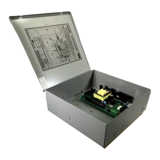
505ULAC Installation Instructions Description of Operation / BoM / Enclosure Features / UL Description of Operation Description of Operation / BoM / Enclosure Features / UL The 505ULAC power supply converts an 110VAC/60 Hz input to a power limited DC output. Output voltage is field selectable for either 13.8 VDC @ 1.0A or 27.6 VDC @ 1.0A nominal. -
Page 4: Product Specifications
505ULAC Installation Instructions Product Specifications Product Specifications Product Specifications Table 1: Product Specifications Electrical Specification Input Voltage 110VAC, 60Hz, 0.5 Amp Output Voltage 1.0A @ 13.8VDC (+/- 5%) or 27.6VDC (+/- 5%) (field selectable) Filtered & Regulated Output Current 1.0A @ rated voltage Primary Fuse Size 800mA, Slo-Blo, 250V. -
Page 5: Installation Procedure
505ULAC Installation Instructions Installing the 505ULAC Installing the 505ULAC 1) Installation Procedure The 505ULAC must be installed in accordance with article 760 of the National Electrical Code or NFPA 72 as well as all applicable local codes. NOTE: Install the 505ULAC indoors within the protected premises. A.) Mounting holes are provided on the back surface of enclosure. -
Page 6: Installation Diagram
505ULAC Installation Instructions Installing the 505ULAC Installation Diagram Refer to the diagram below when wiring the 505ULAC Power Supply. Stand-by batteries shown for 24VDC operation and are wired in series. Figure: 1. Installation Diagram 12VDC 24VDC ENCLOSURE BATTERY DOOR VOLTAGE OUTPUT MONITOR SELECTION... -
Page 7: Stand-By Battery Installation
505ULAC Installation Instructions Stand-by Battery Installation / Terminal Identification Stand-by Battery Installation Stand-by Battery Installation / Terminal Identification 1.) Verify field wiring is complete. 2.) Place batteries upright in bottom of enclosure (See Installation Diagram on page 6). 3.) Using the provided cables, connect batteries (See Installation Diagram on page 6). 4.) Turn on VAC line power input to power supply. -
Page 8: Eir Connection
505ULAC Installation Instructions EIR Connection / LED Diagnostics / Maintenance EIR Connection EIR Connection / LED Diagnostics / Maintenance The purpose of the EIR circuit is to cut power to fail safe locks in an emergency situation. When using the EIR relay circuit to supply power to fail safe locks, such as electromagnetic locks, power must come from connector J6, terminals: -OUT &...
Need help?
Do you have a question about the 505 Series and is the answer not in the manual?
Questions and answers