Advertisement
Quick Links
*44487049*
44487049
Power Supply
These instructions cover the following parts:
R N
W A
!
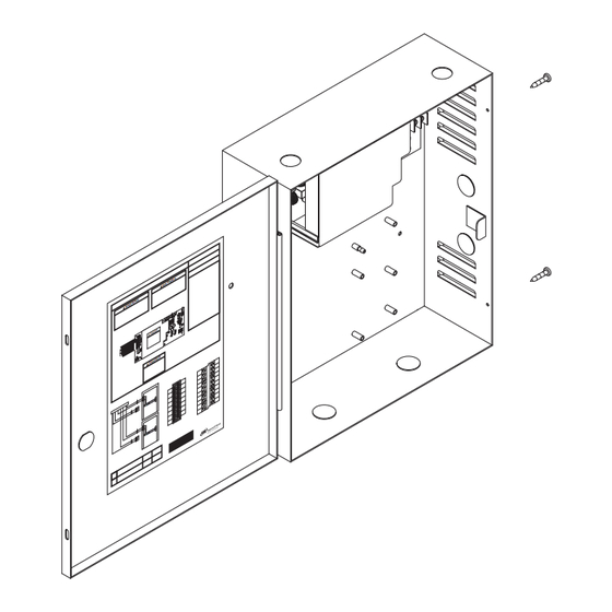
PS906 Power Supply - Pages 1-3
PS906 Power Supply Specifications:
Input
Output
Enclosure
Temperature Range
Fuse
Compliance
Compatible Boards
(Optional, 3 boards maximum)
Fire Alarm Input Board (Optional) 900-FA (Requires one option board above)
Battery Backup Board (Optional)
AC Monitor Output
To avoid risk of electric shock, turn off AC power before
installing or servicing PS906 power supply
:
IN G
R N
W A
!
IN G
:
ER
DA
NG
!
F1
:
E R
N G
D A
!
120/240 VAC, 2.4 A, 50/60Hz, High Voltage Class 1 Wiring Required
6 Amp DC @ 12/24 VDC
14" H x 12" W x 4" D (8 knockouts, 1/2" or 3/4" )
32°-120° F (0°- 49° C)
F1, T6.3A
250 VAC
For protection against risk of fire, replace fuse with same type and rating
UL 294, ULC-S318, RoHS, & FCC Part 15, Class 1 Output
900-2RS
900-4R
900-4RL
900-8F
900-8P
900-BB
Form C Contacts, 30 VDC, 1 Amp, Resistive Load
PS906
DANGER
900-BB Battery Backup (optional) - Page 3
CAuTioN
INST. INSTRUCTIONS - 24125007
INST. INSTRUCTIONS - 44487106
INST. INSTRUCTIONS - 44487080
INST. INSTRUCTIONS - 44487106
INST. INSTRUCTIONS - 44487106
INST. INSTRUCTIONS - 44487072
INST. INSTRUCTIONS - 44487064
Installation Instructions
900-KL Keylock (optional) - Page 2
Advertisement

Related Manuals for Schlage PS906


Summary of Contents for Schlage PS906
- Page 1 44487049 Power Supply Installation Instructions DANGER To avoid risk of electric shock, turn off AC power before installing or servicing PS906 power supply These instructions cover the following parts: 900-KL Keylock (optional) - Page 2 IN G IN G PS906 Power Supply - Pages 1-3...
- Page 2 Mounting notes The PS906 must be installed in accordance with the article 760 of the National Electrical Code or NFPA 72 Canadian Electrical Code, or any other applicable codes. Install the PS906 indoors within the protected premises. Check national and local codes for additional installation requirements.
- Page 3 PS906 Setup and testing Connect AC Wiring AC Input Green (Ground) DANGER AC (In) White (Neutral) Ensure AC breaker is turned off 120/240 Black (Hot) 900-BB Connector DANGER High Voltage If main board must be removed, Use Jumper to Select 24 VDC or 12 turn off AC power and wait 8 minutes before removal.
- Page 4 Turn on AC breaker to test power supply • Verify AC LED is On = GREEN • Verify DC LED is On = RED • Verify BB LED (if applicable) is On = AMBER Refer to appropriate instructions if any board option boards shown below is factory-installed DANGER...
Need help?
Do you have a question about the PS906 and is the answer not in the manual?
Questions and answers