Advertisement
Quick Links
Advertisement

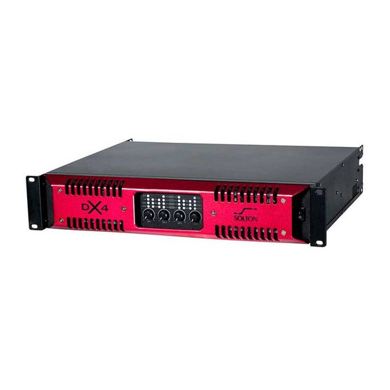
Summary of Contents for Solton DX4
- Page 1 A PRODUCT OF SOLTON ACOUSTIC GERMANY ENGLISH USER MANUAL www.solton-acoustic.de...
-
Page 2: Table Of Contents
Contents Contents.................1 Important note..................2/3 Control elements...............4 Rear panel features introduction ..........5/6 Audio input and output connections ..........7 Stereo Mode................8 Bridge Mode................9 Professional Power Amplifier Specifications .......9... -
Page 3: Important Note
Important Note WARNING NOTICES SAFE GUARDS Electrical energy can perform many useful functions. This unit has been engineered and manufactured to assure your personal safety .Improper use can result in potential electrical Shock or fire hazards .In order not to defeat the safeguards , observe the following precautions for its installation , use and servicing. - Page 4 WARNING User responsibility 4. Speaker damage Your amplifier is very powerful and can be 1. Mains connection grounding potentially dangerous to both loudspeakers and Your amplifier must be connected to a humans alike. Many loudspeakers can be easily grounded socket outlet. damaged or destroyed by overpowering them.
-
Page 5: Control Elements
Control elements F ront panel The front panel LED area includes the following indicators per channel: 1. LEVEL CONTROL Calibrated detente potentiometers to alter the total gain of the power amplifier . In order to avoid distortions in mixing consoles upstream , these controls should normally be positioned between 0 and 10 . -
Page 6: Rear Panel Features Introduction
Rear panel features introduction CHA/CHC PARALLEL STEREO 2 channel version Mains input 200V DIP switches XLR connectors for 4 channel version shown with Neutik or 240V operation for adjusting key inputs and loop thru shown with Neutrik Speakon output features Speakon output connectors (See below) - Page 7 VCL - Voltage Clip Limiter adjustment is provided for eight VCL - VOLTAGE CLIP LIMITER discrete levels for each channel for each channel. Select the 150V setting most appropriate for connected speakers. 121V 101V Mode - Select VCL mode to either Hard or Soft operation. For VCL - in Bridge Mode channels driving sub-woofers and low-frequency drivers, it is 300V...
-
Page 8: Audio Input And Output Connections
Audio input and output connections BALANCED INPUT CONNECTIONS The XLR input connectors are electronically balanced, and wired according to the IEC 268 standard(pin 2 = hot). XLR input connectors should be wiredas follows: Pin 1 Ground/shield Pin 2 Hot (+) Pin 3 Cold (-) Audio inputs - 4-channel models When linking the same source signal to several input channels, be aware... -
Page 9: Stereo Mode
Stereo Mode Before setting the mode , please turn off the amplifier and GAIN 44dB slide the mode select switch to below (Picture 1) .In this 41dB 38dB mode, Channel A an Channel B operate independently (just 35dB traditional stereo amplifier). The signal input into channel A 32dB 29dB can be output from channel A only, similarly, the signal input... -
Page 10: Professional Power Amplifier Specifications
Rear panel features introduction Amplifier Specifications VOLTAGE PEAK LIMITER OUTPUT POWER PER CHANNEL (W) LOAD VPL Setting V peak Vrms 16 Ohms 8 Ohms 4 Ohms 2 Ohms 150 V 1240 2485 2500 121 V 1740 2500 101 V 1250 2500 83 V 1805... - Page 11 Rear panel features introduction Amplifier Specifications Model Output Power 8 Stereo Power 4 x 1300W 4 Stereo Power 4 x 2200W 2 Stereo Power 4 x 2500W 8 Bridged Monon Power 2 x 4400W 2 x 5000W 4 Bridged Monon Power FREQUENTY RESPONSE 20Hz-25kHz 0.5dB...
- Page 12 Tel: +49 (0) 8531 / 913880 Fax: +49 (0) 8531 / 978507 Web: www.solton.de E-mail: info@solton-acousitc.de All rights reserved to SOLTON Acoustic. All features and content might be changed without prior notice. Any photocopy, translation, or reproduction of part of this manual without written permission is forbidden.


Need help?
Do you have a question about the DX4 and is the answer not in the manual?
Questions and answers
My amplifier DX4 is protected
The context does not explicitly define "protection mode" for the Solton DX4 amplifier. However, based on standard amplifier behavior and related safety information, protection mode generally means the amplifier has detected a problem such as overheating, a short circuit, or improper load, and has shut down or limited operation to prevent damage. This mode helps protect internal components and connected equipment until the issue is resolved.
This answer is automatically generated