Table of Contents
Advertisement
Quick Links
HIL / HIH
HIL
1
A1
A2 E3 E2 E1 M
2
Undercurrent
Overcurrent
3
No Memory
No M
Memory
M
I Value
30
80
20
90
4
10
100%
15
40
Hysteresis
10
45
5
50%
8 10 12 14
1
2
6
16
5
4
18
Un
2
1
20s
0,1
3s
Ti
Tt
R
6
7
12
11
14
22 21 24
8
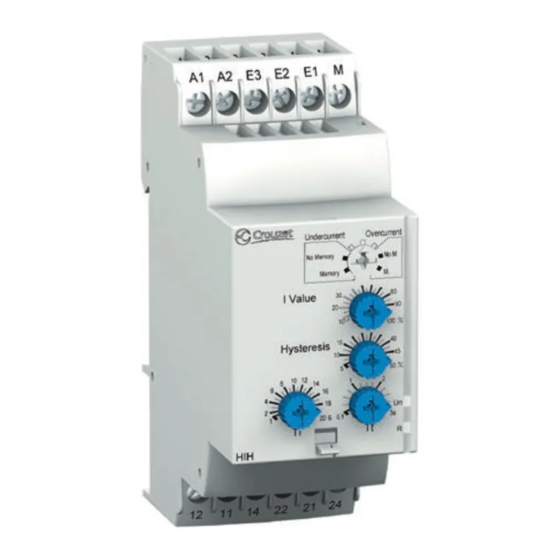
1 - Configuration: selection of the active function (Undercurrent/Overcurrent)
and the operating mode (with or without memory: Memory - No Memory)
2 - Current threshold adjusting potentiometer. I Value
3 - Hysteresis control potentiometer. Hysteresis
4 - Time delay control potentiometer. Tt
5 - Power supply status (green) LED. Un
6 - Relay output status (yellow) LED. R
7 - Startup inhibition delay control potentiometer. Ti
8 - 35 mm rail clip-in spring.
1 - Configuration : choix de la fonction active (Undercurrent/Overcurrent)
et du mode de fonctionnement (avec ou sans mémoire : Memory - No Memory)
2 - Potentiomètre de réglage du seuil de courant. I Value
3 - Potentiomètre de réglage de l'hystérésis. Hysteresis
4 - Potentiomètre de réglage de la temporisation. Tt
5 - LED d'état (verte) de l'alimentation. Un
6 - LED d'état (jaune) de la sortie relais. R
7 - Potentiomètre de réglage de la temporisation d'inhibition au démarrage. Ti
8 - Ressort de clipsage sur rail de 35 mm.
1 - Konfiguration: Wahl der aktiven Funktion (Undercurrent/Overcurrent)
und des Betriebsmodus (mit oder ohne Speicher: Memory - No Memory)
2 - Potentiometer zur Einstellung des Stromschwellenwerts. I Value
3 - Potentiometer zur Einstellung der Hysterese. Hysteresis
4 - Potentiometer zur Einstellung der Verzögerung. Tt
5 - Status-LED (grün) der Stromversorgung. Un
6 - Status-LED (gelb) des Relaisausgangs. R
7 - Potentiometer zur Einstellung der Anlauf-Überbrückungsverzögerung. Ti
8 - Klemmfeder auf 35 mm Schiene.
1
2
Click!
6
mm
0.24
inch
mm 2
0,5...2,5
AWG
20...14
Pozidriv n° 0
Ø 4 mm/
0.16 inch
HIH
1
A1
A2 E3 E2 E1 M
2
Undercurrent
Overcurrent
3
No Memory
No M
Memory
M
I Value
30
80
20
90
4
10
100%
15
40
Hysteresis
10
45
5
50%
8 10 12 14
1
2
6
16
5
4
18
Un
2
1
20s
0,1
3s
Ti
Tt
R
6
7
12
11
14
22 21 24
8
0,5...1,5
20...16
Nm
0,6...1
lb-inch
5.3...8.8
A1
A2 E3 E2 E1 M
I Value
Hysteresis
Un
Ti
Tt
R
12
11
14
22 21 24
35/1.38
1 - Configuración: selección de la función activa (Undercurrent/Overcurrent)
y del modo de funcionamiento (con o sin memoria: Memory - No Memory)
2 - Potenciómetro de ajuste del umbral de corriente. I Value
3 - Potenciómetro de ajuste de la histéresis. Hysteresis
4 - Potenciómetro de ajuste de la temporización. Tt
5 - LED de estado (verde) de la alimentación. Un
6 - LED de estado (amarillo) de la salida relé. R
7 - Potenciómetro de ajuste de la temporización de inhibición
en el arranque. Ti
8 - Molla di aggancio su barra metallica da 35 mm.
1 - Configurazione: scelta della funzione attiva (Undercurrent/Overcurrent)
e della modalità di funzionamento
( con o sin memoria: Memory - No Memory)
2 - Potenziometro di regolazione della soglia di corrente. I Value
3 - Potenziometro di regolazione dell'isteresi. Hysteresis
4 - Potenziometro di regolazione della temporizzazione. Tt
5 - LED di stato (verde) dell'alimentazione. Un
6 - LED di stato (giallo) dell'uscita relè. R
7 - Potenziometro di regolazione della temporizzazione d'inibizione
all'avviamento. Ti
8 - Resorte de clipsado en carril 35 mm.
Rail 35 mm /1.38 inch
Rail 35 mm /1.38 inch
Schiene 35 mm /1.38 inch
Riel 35 mm /1.38 inch
2
Guida 35 mm /1.38 inch
1
Typical
value
c 24 V
2 x 5 A
a 24 V
2 x 5 A
a 250 V max
2 x 5 A
69/2.72
IEC/EN 60715
100 000
2 x 1 A
100 000
100 000
2 x 2 A
100 000
100 000
2 x 2 A
100 000
mm
inch
NTR 1002 C
05 - 2008
1/4
Advertisement
Table of Contents

Subscribe to Our Youtube Channel
Related Manuals for Crouzet HIL


Summary of Contents for Crouzet HIL
- Page 1 HIL / HIH A2 E3 E2 E1 M A2 E3 E2 E1 M A2 E3 E2 E1 M Undercurrent Overcurrent Undercurrent Overcurrent No Memory No M No Memory No M Memory Memory I Value I Value I Value 100% 100%...
- Page 2 No responsibility is assumed by Crouzet n'assume aucune Crouzet haftet nicht für Schäden, Crouzet no asume las Crouzet non assume nessuna Crouzet for any consequences responsabilité des conséquences die aufgrund der Verwendung responsabilidades que pudieran responsabilità...
- Page 3 HIL / HIH (1) 1 A fast-acting fuse. UL…Class CC ; IEC…gG – KM1 Fusible rapide 1 A. UL…Class CC ; IEC…gG Schnellsicherung 1 A. UL…Klasse CC ; IEC…gG Fusible rápido 1 A. UL…Clase CC ; IEC…gG Fusibile rapido 1 A. Omologato UL…Classe CC ; IEC…gG –/+...
- Page 4 In your system, when there is complete galvanic insulation between the power supply A1/A2 and the measurement circuit Ep/M (p = 1, 2, 3), all combinations of wiring a/c are acceptable. But if this is not the case, please take into account the recommendations below. Lorsqu'une isolation galvanique totale est garantie entre l'alimentation A1/A2 et le circuit de mesure Ep/M (p = 1, 2, 3) de votre système, différentes combinaisons de câblage a/c sont acceptables.
Need help?
Do you have a question about the HIL and is the answer not in the manual?
Questions and answers