Table of Contents
Advertisement
Quick Links
OM2247 August 5, 2016
it's all about connections
Manual
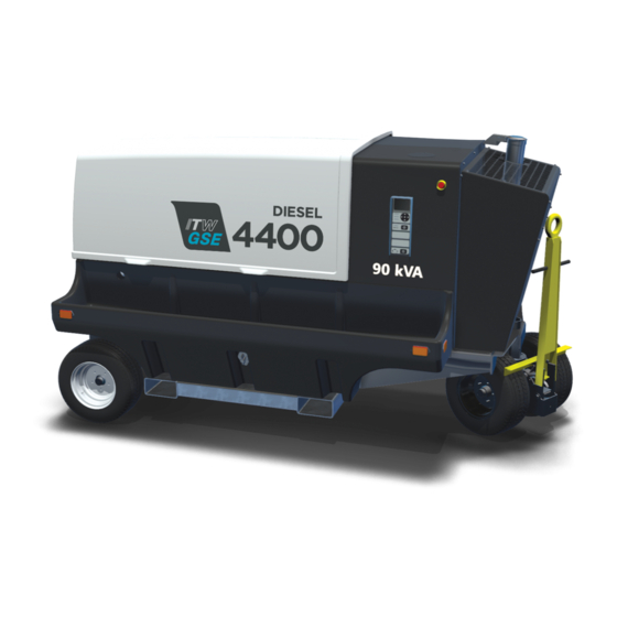
ITW GSE 4400
60-90 kVA, 3 Phase, 115 Volt,
400 Hz Tier 4 Generator Set
Series no.
500106-500107
Type
4400
●
●
●
ITW GSE HOBART
11001 Us Highway 41 North
Palmetto, FL 34221
U.S.A
●
●
T: (toll free in US): 800-899-1841
T (International): + 1 941-721-1000
E: sales@itwgse.us
Advertisement
Table of Contents
Troubleshooting

Subscribe to Our Youtube Channel
Related Manuals for ITW GSE Hobart 4400


Summary of Contents for ITW GSE Hobart 4400
- Page 1 OM2247 August 5, 2016 it’s all about connections Manual ITW GSE 4400 60-90 kVA, 3 Phase, 115 Volt, 400 Hz Tier 4 Generator Set Series no. 500106-500107 Type 4400 ● ● ● ITW GSE HOBART 11001 Us Highway 41 North Palmetto, FL 34221 U.S.A...
- Page 3 OM-2247 / Operation and Maintenance Manual ITW GSE 4400 / 400 Hz. Tier 4 Generator Set Introduction This manual contains operation and maintenance information for a diesel engine-generator manufactured by ITW GSE, Palmetto, Florida 34221 This manual, including all information contained therein, is exclusive and confidential property of ITW GSE.
- Page 4 OM-2247 / Operation and Maintenance Manual ITW GSE 4400 / 400 Hz. Tier 4 Generator Set If you have any questions concerning your ITW GSE equipment, immediately contact our Service Department by mail, telephone, FAX, or E-Mail. Write: ITW GSE...
- Page 5 OM-2247 / Operation and Maintenance Manual ITW GSE 4400 / 400 Hz. Tier 4 Generator Set Safety Warnings and Cautions. WARNING ELECTRIC SHOCK can KILL. Do not touch live electrical parts. ELECTRIC ARC FLASH can injure eyes, burn skin, cause equipment damage, and ignite combustible material.
- Page 6 OM-2247 / Operation and Maintenance Manual ITW GSE 4400 / 400 Hz. Tier 4 Generator Set 3) Service and Maintenance This equipment must be maintained in good electrical condition to avoid hazards stemming from disrepair. Report any equipment defect or safety hazard to the supervisor and discontinue use of the equipment until its safety has been assured.
- Page 7 OM-2247 / Operation and Maintenance Manual ITW GSE 4400 / 400 Hz. Tier 4 Generator Set 7) Medical and First Aid Treatment. First aid facilities and a qualified first aid person should be available for each shift for immediate treatment of all injury victims.
- Page 8 OM-2247 / Operation and Maintenance Manual ITW GSE 4400 / 400 Hz. Tier 4 Generator Set This page is intentionally left blank. August 5, 2016 Safety Warnings Page 4...
- Page 9 OM-2247 / Operation and Maintenance Manual ITW GSE 4400 / 400 Hz. Tier 4F Generator Set Table of Contents Chapter 1 Description/Operation Chapter-Section/Page# Section 1 Description 1-1/1 1) General 1-1/1 2) Optional Equipment - Appendix A and B 1-1/1 3) Component Locations...
- Page 10 OM-2247 / Operation and Maintenance Manual ITW GSE 4400 / 400 Hz. Tier 4F Generator Set 4.7) EF Interlock Ripple Level 1-3/16 4.8) EF Interlock Delay 1-3/17 4.9) Aircraft Connector Insertion 1-3/17 4.10) Cable Temperature 1-3/17 4.11) Allow Engine Idle 1-3/17 4.12) Automatic Engine Shutdown...
- Page 11 OM-2247 / Operation and Maintenance Manual ITW GSE 4400 / 400 Hz. Tier 4F Generator Set k) “G Checks and Operations (5000 Hours or 4 Years) 2-1/12 l) Lamps and Fuses 2-1/13 Section 2 Maintenance Procedures 2-2/1 1) General 2-2/1...
- Page 12 OM-2247 / Operation and Maintenance Manual ITW GSE 4400 / 400 Hz. Tier 4F Generator Set Section 3 Troubleshooting Procedures 2-3/1 1) General 2-3/1 2) Equipment for Troubleshooting 2-3/1 3) Parts Replacement 2-3/1 4) Normal Operational Parameters 2-3/1 5) Check Connections and Leads...
- Page 13 OM-2247 / Operation and Maintenance Manual ITW GSE 4400 / 400 Hz. Tier 4F Generator Set Figure 3-5. Fuel Tank Composite Assembly 3-2/19 Figure 3-6. Radiator/After-Treatment Installation 60-90 kVA T-4 3-2/23 Figure 3-7. Coolpack, Radiator Assy 60-90 kVA 3-2/26 Figure 3-9. Output Table Assembly, Single Output 3-2/29 Figure 3-10.
- Page 14 Description 1) General The basic generator sets covered in this manual, manufactured by ITW GSE Group, are rated at 60kVA and 90kVA they are designed to produce and deliver 115/200-volt, 400 Hz, 3-phase AC power to a parked aircraft or other load. Some generator models with the Active Rectified Unit (ARU) option also provide 28.5 volts DC for aircraft having those requirements.
- Page 15 OM-2247 / Operation and Maintenance Manual ITW GSE 4400 / 400 Hz. Tier 4 Generator Set 3) Component Locations For purpose of orientation when designating RIGHT and LEFT throughout this manual, the radiator is considered to be at the FRONT of the unit and the generator is at the REAR. RIGHT and LEFT are determined by standing at the REAR facing the machine.
- Page 16 OM-2247 / Operation and Maintenance Manual ITW GSE 4400 / 400 Hz. Tier 4 Generator Set 1. Cummins QSB4.5 T4 Engine 6. Generator 2. Control Module Assembly 7. 28.5 VDC ARU (Option) 3. Batteries (inside tray pockets) 8. Engine Alternator 4.
- Page 17 OM-2247 / Operation and Maintenance Manual ITW GSE 4400 / 400 Hz. Tier 4 Generator Set 1. Coolant fill access cover 6. Engine Oil Fill Tube 2. Lubricity Additive Fuel Pre-Filter 7. Charge-Air-Cooler Piping 3. Fuel Filter 8. Engine Air Filter 4.
- Page 18 OM-2247 / Operation and Maintenance Manual ITW GSE 4400 / 400 Hz. Tier 4 Generator Set 1. Oil Drain Valve 2. Tie Down Rings (Option) 3. DOC Diesel Oxidation Catalyst 4. SRC Selective Catalytic Reduction 5. DEF Fluid Holding Tank 6.
- Page 19 OM-2247 / Operation and Maintenance Manual ITW GSE 4400 / 400 Hz. Tier 4 Generator Set b) Physical Specifications 112.1 in. (2847 mm) w/ towbar Length Width 66.7 in. (1694 mm) Height 63.9 in. (1622 mm) Weight (dry) 4000 lb. (1814 kg.) Weight with 28.5 VDC ARU...
- Page 20 OM-2247 / Operation and Maintenance Manual ITW GSE 4400 / 400 Hz. Tier 4 Generator Set e) DC Output Specifications (with optional TR unit) Output Power Rating 17.1 kW Output Voltage 28.5 VDC Load Capacity (Continuous) 600 A 300 to 2000 A in selectable steps...
- Page 21 OM-2247 / Operation and Maintenance Manual ITW GSE 4400 / 400 Hz. Tier 4 Generator Set 5) Special Features The generator set has special features that are described more fully under the assemblies in which they appear. a) Protective Monitoring...
- Page 22 OM-2247 / Operation and Maintenance Manual ITW GSE 4400 / 400 Hz. Tier 4 Generator Set The after-treatment DEF dosing unit pumps DEF from the DEF tank to the after-treatment dosing valve. The DEF dosing unit is electrically heated, and contains a filter that is a maintenance item.
- Page 23 OM-2247 / Operation and Maintenance Manual ITW GSE 4400 / 400 Hz. Tier 4 Generator Set The fuel filter is a spin-on disposable type located on the inside of the canopy, near the engine’s fuel pump. The fuel filter’s primary function, other than removing contaminants from the fuel, is to automatically add a lubricity additive to the fuel.
- Page 24 OM-2247 / Operation and Maintenance Manual ITW GSE 4400 / 400 Hz. Tier 4 Generator Set (3) Engine-cooling fan The engine fan is designed to blow air outward through the radiator, rather than pulling the air inward as a conventional fan does.
- Page 25 OM-2247 / Operation and Maintenance Manual ITW GSE 4400 / 400 Hz. Tier 4 Generator Set the engine flywheel by a flexible coupling assembly. The rear end of the rotor shaft extends rearward beyond the rear bearing and into the exciter stator housing. The exciter rotor is mounted on this shaft extension with a key and is secured by a washer and 1/2-13 thread cap screw.
- Page 26 OM-2247 / Operation and Maintenance Manual ITW GSE 4400 / 400 Hz. Tier 4 Generator Set b) Operator Controls – Operator Panel 1. LED Graphical Display 5. Alert/Failure "Red" LED 2. Navigation Keypad 6. Output ON "Green" LEDs 3. Power ON "Blue" LED 7.
- Page 27 OM-2247 / Operation and Maintenance Manual ITW GSE 4400 / 400 Hz. Tier 4 Generator Set engine. If the engine is already running, it will begin the manufacturer required 30 second cool down. If the unit has a fault, this button will reset the fault.
- Page 28 OM-2247 / Operation and Maintenance Manual ITW GSE 4400 / 400 Hz. Tier 4 Generator Set Unit information is displayed using the Parameter Information icon. To access the information icon, press the ● from the default menu and hold it down for approximately 5 seconds.
- Page 29 OM-2247 / Operation and Maintenance Manual ITW GSE 4400 / 400 Hz. Tier 4 Generator Set August 5, 2016 Chapter 1-1 Page 16...
- Page 30 OM-2247 / Operation and Maintenance Manual ITW GSE 4400 / 400 Hz. Tier 4 Generator Set Power Module Assembly The power module assembly, mounted to the back of the ARU bracket, is located at the rear of the machine over the generator. The panel assembly provides a means of connecting and disconnecting the generator output to and from the aircraft.
- Page 31 OM-2247 / Operation and Maintenance Manual ITW GSE 4400 / 400 Hz. Tier 4 Generator Set 10) Cold Weather Starting System (BH1) The intake air heater, located on the intake manifold, is used for starting the engine at very cold temperatures and reduces the white smoke associated with a cold start.
- Page 32 OM-2247 / Operation and Maintenance Manual ITW GSE 4400 / 400 Hz. Tier 4 Generator Set 11) Active Rectifier Unit (ARU) The ARU provides a regulated output voltage of 28.5 VDC. Power is provided to the DC components from the 115/200 volt, 400 Hz generator set, through input contactor Q3. Both 400 Hz & 28 VDC outputs can be used simultaneously.
- Page 33 OM-2247 / Operation and Maintenance Manual ITW GSE 4400 / 400 Hz. Tier 4 Generator Set • Interface for heat sink thermostat (X5) • Input for current transformer T20 (X6) Resistor (R20): The discharge resistor R20 is part of the output filter stage and discharges the capacitor C20, when the unit is turned off.
- Page 34 OM-2247 / Operation and Maintenance Manual ITW GSE 4400 / 400 Hz. Tier 4F Generator Set Section 2 Preparation for Use, Storage, or Shipping 1) Preparation for use after receipt of unit a) Inspection/Check Inspect the unit thoroughly prior to operation.
- Page 35 OM-2247 / Operation and Maintenance Manual ITW GSE 4400 / 400 Hz. Tier 4F Generator Set (10) Check the engine lubricating oil level. The oil gauge rod has H high mark and L low-level marks to indicate the operating lubrication oil supply. Oil level should be kept as near the high mark as possible, without going over it.
- Page 36 OM-2247 / Operation and Maintenance Manual ITW GSE 4400 / 400 Hz. Tier 4F Generator Set b) Installing Three-Phase AC Output Cables Figure 1-2-3 Figure 1-2-4 Figure 1-2-5 The generator set may be shipped without aircraft cables. The output cables connect to the load contactors, which are located at the rear of the unit.
- Page 37 OM-2247 / Operation and Maintenance Manual ITW GSE 4400 / 400 Hz. Tier 4F Generator Set (7) Tighten the clamp screws securely, but avoid damage to the cable insulation. (8) Replace the canopy. c) Installing the DC Output Cable (optional) (1) Remove canopy.
- Page 38 OM-2247 / Operation and Maintenance Manual ITW GSE 4400 / 400 Hz. Tier 4F Generator Set 2) Preparation for Storage When a generator set is to be stored or removed from operation, special precautions should be taken to protect the internal and external parts from rust, corrosion, and gumming in the engine fuel system.
- Page 39 OM-2247 / Operation and Maintenance Manual ITW GSE 4400 / 400 Hz. Tier 4F Generator Set (2) Start the engine and operate under full load (using a resistive load bank or aircraft) until the coolant temperature has reached at least 176ºF (80ºC).
- Page 40 OM-2247 / Operation and Maintenance Manual ITW GSE 4400 / 400 Hz. Tier 4F Generator Set Section 3 Operation 1) General This section contains information and instructions for the safe and efficient operation of the equipment. Operating instructions are presented in systematic sequence of procedures to be followed in supplying 400-Hz or 28.5 VDC power.
- Page 41 OM-2247 / Operation and Maintenance Manual ITW GSE 4400 / 400 Hz. Tier 4F Generator Set 1. LED Graphical Display 5. Alert/Failure "Red" LED 6. Output ON "Green" LEDs 2. Navigation Keypad 3. Power ON "Blue" LED 7. Output ON/OFF (Reset) * 4.
- Page 42 OM-2247 / Operation and Maintenance Manual ITW GSE 4400 / 400 Hz. Tier 4F Generator Set CAUTION To eliminate the possibility of wet stacking (See Appendix C), DO NOT allow the engine to idle for long periods. c) Failed Starting Procedure In the event that there is an error during initialization or if the engine fails to start after 3 automatic attempts (15 seconds crank, 15 seconds wait per attempt), the display will show a fault.
- Page 43 OM-2247 / Operation and Maintenance Manual ITW GSE 4400 / 400 Hz. Tier 4F Generator Set ● 1. Press and hold for approximately 5 seconds. ● ◄▼▲► 2. Use navigation keys ( ) to highlight the setup icon. Press to select.
- Page 44 OM-2247 / Operation and Maintenance Manual ITW GSE 4400 / 400 Hz. Tier 4F Generator Set g) Low Fuel Warning and Fault A Low Fuel Warning occurs when the unit is running and the fuel level drops below 10% in the fuel tank.
- Page 45 OM-2247 / Operation and Maintenance Manual ITW GSE 4400 / 400 Hz. Tier 4F Generator Set ii) Once the correct value is selected, use the below procedure to start the unit. Note: To ensure hassle-free starting of the aircraft engine, the current limit function is delayed 0.7 seconds.
- Page 46 OM-2247 / Operation and Maintenance Manual ITW GSE 4400 / 400 Hz. Tier 4F Generator Set Note! Please note that the 28 VDC Start/Stop button also functions as a Reset push button. If, for some reason, the unit stops due to an error / failure, record the fault number and message and forward this information to your maintenance personnel.
- Page 47 OM-2247 / Operation and Maintenance Manual ITW GSE 4400 / 400 Hz. Tier 4F Generator Set Icon Menu The Icon Menu is accessed from the Default screen. Press the center navigation button ● while in the default menu and hold it down for approximately 5 seconds.
- Page 48 OM-2247 / Operation and Maintenance Manual ITW GSE 4400 / 400 Hz. Tier 4F Generator Set 4.0.1 View Parameters Menu The View Parameters Menu is accessed from the Icon screen. Press the center navigation button ● while in the default menu and hold it down for approximately 5 seconds. The Icon menu is displayed, press the right navigation button to highlight the icon.
- Page 49 OM-2247 / Operation and Maintenance Manual ITW GSE 4400 / 400 Hz. Tier 4F Generator Set 4.0.2 Setup Menu The Setup Menu is accessed from the Icon screen. Press the center navigation button ● while in the default menu and hold it down for approximately 5 seconds. The Icon menu is displayed, press the right navigation button to highlight the Setup icon.
- Page 50 OM-2247 / Operation and Maintenance Manual ITW GSE 4400 / 400 Hz. Tier 4F Generator Set August 5, 2016 Chapter 1-3 Page 11...
- Page 51 OM-2247 / Operation and Maintenance Manual ITW GSE 4400 / 400 Hz. Tier 4F Generator Set August 5, 2016 Chapter 1-3 Page 12...
- Page 52 OM-2247 / Operation and Maintenance Manual ITW GSE 4400 / 400 Hz. Tier 4F Generator Set August 5, 2016 Chapter 1-3 Page 13...
- Page 53 OM-2247 / Operation and Maintenance Manual ITW GSE 4400 / 400 Hz. Tier 4F Generator Set August 5, 2016 Chapter 1-3 Page 14...
- Page 54 OM-2247 / Operation and Maintenance Manual ITW GSE 4400 / 400 Hz. Tier 4F Generator Set Output Voltage: This Setup submenu allows the output voltage to be adjusted between 80.0 VAC and 135 VAC using the UP and DOWN navigation buttons. (Please note that the acceptable voltage range for all commercial aircraft is 115V ±3V.
- Page 55 OM-2247 / Operation and Maintenance Manual ITW GSE 4400 / 400 Hz. Tier 4F Generator Set the aircraft. The aircraft will evaluate the 400 Hz power and if it is within the aircrafts tolerance limits it will then close a relay in the aircraft to provide a 28VDC signal to the “F” pin/wire in the power connector plug/cable.
- Page 56 OM-2247 / Operation and Maintenance Manual ITW GSE 4400 / 400 Hz. Tier 4F Generator Set Go into the Setup Menu and then scroll up or down to the EF Interlock Delay submenu. Press the center ● button to enter the submenu, and then press the ● button again to allow the value to be changed. Press the up or down arrow buttons to change the selection.
- Page 57 OM-2247 / Operation and Maintenance Manual ITW GSE 4400 / 400 Hz. Tier 4F Generator Set 4.13 Real Time Clock Setup This set of sub-menu s allows the user to adjust the internal clock to the correct local time. Go into the Setup Menu and then scroll up or down to the Real Time Clock Setup submenu. Press the center ●...
- Page 58 OM-2247 / Operation and Maintenance Manual ITW GSE 4400 / 400 Hz. Tier 4F Generator Set the up or down arrow buttons to change the selection. Press the center ● button to record the new value. Press the LEFT arrow button to exit the submenu and return to the submenu list.
- Page 59 OM-2247 / Operation and Maintenance Manual ITW GSE 4400 / 400 Hz. Tier 4F Generator Set Enter the Setup Menu and then scroll up or down to the Diagnostic Mode submenu. Press the center ● button to enter the submenu, and then press the ● button again to allow the value to be changed. Press the up or down arrow buttons to change the selection.
- Page 60 OM-2247 / Operation and Maintenance Manual ITW GSE 4400 / 400 Hz. Tier 4F Generator Set 4.26 Language This submenu is used to change the language that all of the display screens, messages, alarms and reports are displayed in. The unit comes with English, French, German, Italian, Polish, Portuguese, Czech, Russian, Turkish and Spanish already installed.
- Page 61 OM-2247 / Operation and Maintenance Manual ITW GSE 4400 / 400 Hz. Tier 4F Generator Set 4.3) Black Box The Black Box Menu is accessed from the Icon screen. Press the center navigation button ● while in the default menu and hold it down for approximately 5 seconds. The Icon menu is displayed, press the right navigation button to highlight the Black Box icon.
- Page 62 OM-2247 / Operation and Maintenance Manual ITW GSE 4400 / 400 Hz. Tier 4F Generator Set 4.4) Power Log The Power Log Menu is accessed from the Icon screen. Press the center navigation button ● while in the default menu and hold it down for approximately 5 seconds. The Icon menu is displayed, press the right navigation button to highlight the Power Log icon.
- Page 63 OM-2247 / Operation and Maintenance Manual ITW GSE 4400 / 400 Hz. Tier 4F Generator Set 4.5) Update/Save Log Menu The Update/Save Log Menu is accessed from the Icon screen. Press the center navigation button ● while in the default menu and hold it down for approximately 5 seconds. The Icon menu is displayed, press the right navigation button then the down button to highlight the Update/Save Log icon.
- Page 64 OM-2247 / Operation and Maintenance Manual ITW GSE 4400 / 400 Hz. Tier 4F Generator Set August 5, 2016 Chapter 1-3 Page 25...
- Page 65 OM-2247 / Operation and Maintenance Manual ITW GSE 4400 / 400 Hz. Tier 4F Generator Set August 5, 2016 Chapter 1-3 Page 26...
- Page 66 OM-2247 / Operation and Maintenance Manual ITW GSE 4400 / 400 Hz. Tier 4F Generator Set Chapter 2 Service and Troubleshooting Section 1 Maintenance Inspection/Check 1) General To make certain the generator set is always ready for operation, it must be inspected and maintained regularly and systematically so that defects may be discovered and corrected before they result in serious damage to components, or failure of the equipment.
- Page 67 OM-2247 / Operation and Maintenance Manual ITW GSE 4400 / 400 Hz. Tier 4F Generator Set Hourly Interval 50-150 1000 2000 4500 5000 Calendar Interval Once Daily 3 Mo. 6 Mo. 1 Yr. 2 Yr. 3 Yr. 4 Yr. Symbol...
- Page 68 OM-2247 / Operation and Maintenance Manual ITW GSE 4400 / 400 Hz. Tier 4F Generator Set Hourly Interval 50-150 1000 2000 4500 5000 Calendar Interval Once Daily 3 Mo. 6 Mo. 1 Yr. 2 Yr. 3 Yr. 4 Yr. Symbol...
- Page 69 OM-2247 / Operation and Maintenance Manual ITW GSE 4400 / 400 Hz. Tier 4F Generator Set 3) Inspection/Checks a) General See Chapter 2-2 for detailed maintenance procedures. See Chapter 2-3 for adjustment and test procedures. Check the Cummins Engine manual Section 2 – Maintenance Guidelines, page 2-2 for Tool Requirements.
- Page 70 OM-2247 / Operation and Maintenance Manual ITW GSE 4400 / 400 Hz. Tier 4F Generator Set Check coolant additive concentration. Refer to the engine manufacturer’s operations manual for assistance. Steam clean the engine to free it of oil and dirt to prevent uneven engine cooling “hot spots”.
- Page 71 OM-2247 / Operation and Maintenance Manual ITW GSE 4400 / 400 Hz. Tier 4F Generator Set (iv) Tighten the drain valve. Safely dispose of drained fuel. (vi) Purge air from fuel system if necessary. Water Drain Valve Figure 2-1-2 Fuel Lubricity Drain e.
- Page 72 OM-2247 / Operation and Maintenance Manual ITW GSE 4400 / 400 Hz. Tier 4F Generator Set Check Exhaust System. Visually inspect muffler and exhaust pipes for rust and signs of approaching failure. Listen for any gasket or joint leaks. WARNING A leaking and defective exhaust system could be a fire hazard.
- Page 73 OM-2247 / Operation and Maintenance Manual ITW GSE 4400 / 400 Hz. Tier 4F Generator Set e) “B” Check and Operations (250 Hours or 3 Months). (1) Engine. Prevent Diesel Engines Wet Stacking. All diesel engines operated for extended periods under light load may develop a condition commonly referred to as wet-stacking.
- Page 74 OM-2247 / Operation and Maintenance Manual ITW GSE 4400 / 400 Hz. Tier 4F Generator Set (3) Electrical (400 Hz System). Check the operation of the E-F bypass system. “C” Checks and Operations (500 Hours or 6 Months) (1) Engine.
- Page 75 OM-2247 / Operation and Maintenance Manual ITW GSE 4400 / 400 Hz. Tier 4F Generator Set Clean and inspect generally. g) “D” Checks and Operations (1000 Hours or 1 Year) (1) Engine. Check Fan Hub and Drive Pulley. Inspect for loose bolts or worn features. Tighten bolts and replace parts if necessary. Refer to the engine manufacturer’s operations and maintenance manual for assistance and the...
- Page 76 OM-2247 / Operation and Maintenance Manual ITW GSE 4400 / 400 Hz. Tier 4F Generator Set h) “E” Checks and Operations (2000 Hours or 2 Years) (1) Engine. Steam Clean Engine. There are several reasons why the engine exterior should be kept clean. Dirt on the outside will enter fuel and oil filter cases and rocker housings when covers are removed, unless dirt is removed first.
- Page 77 OM-2247 / Operation and Maintenance Manual ITW GSE 4400 / 400 Hz. Tier 4F Generator Set Seasonal Maintenance Checks Spring/Fall (Engine). (1) Check Fan Mounting. Check fan to be sure it is securely mounted. Check for fan wobble and/or broken/cracked blades.
- Page 78 OM-2247 / Operation and Maintenance Manual ITW GSE 4400 / 400 Hz. Tier 4F Generator Set Section 2 Maintenance Procedures 1) General A suggested maintenance schedule is provided in Section 1 of this Servicing Chapter. Each step of the schedule is also covered in general in Section 1. This Section covers maintenance in more detail, where necessary.
- Page 79 OM-2247 / Operation and Maintenance Manual ITW GSE 4400 / 400 Hz. Tier 4F Generator Set 2) Engine Lubrication a) General Proper lubrication is one of the most important steps in good maintenance procedure. Proper lubrication means the use of correct lubricants and adherence to a proper time schedule. Lubrication points, frequency of lubrication, recommended lubricants and filters are indicated in Figures 2-2-1 and 2-2-2.
- Page 80 OM-2247 / Operation and Maintenance Manual ITW GSE 4400 / 400 Hz. Tier 4F Generator Set c) Changing engine oil Change the oil once after the first 50 - 150 hours of use and then every 500 hours of engine operation thereafter.
- Page 81 OM-2247 / Operation and Maintenance Manual ITW GSE 4400 / 400 Hz. Tier 4F Generator Set Change oil as follows: (1) Provide an open container for catching the old oil below the oil drain plug. Container capacity must be greater than 30 quarts (28.4 liters).
- Page 82 OM-2247 / Operation and Maintenance Manual ITW GSE 4400 / 400 Hz. Tier 4F Generator Set Acceptable Lubricants d) Engine Accessories Lubrication (1) Alternator Most alternators contain sealed bearings and require no periodic lubrication, however, check to make certain there are no lubrication points on your particular alternator.
- Page 83 OM-2247 / Operation and Maintenance Manual ITW GSE 4400 / 400 Hz. Tier 4F Generator Set Servicing the Air Cleaner A definite time schedule for cleaning or changing the air cleaner cannot be determined because of varying operating conditions. Pull the yellow tab out (about 1 inch) then rotate the hub counter-clockwise about one inch and pull it off of the housing to access the air cleaner filter.
- Page 84 OM-2247 / Operation and Maintenance Manual ITW GSE 4400 / 400 Hz. Tier 4F Generator Set (3) Pull out air filter elements and replace. (4) Replace end cover on housing, making certain that the filter is centered in the housing.
- Page 85 OM-2247 / Operation and Maintenance Manual ITW GSE 4400 / 400 Hz. Tier 4F Generator Set 5) Engine Fuel System The fuel system consists of five primary components: fuel tank, lubricity filter, primary fuel filter, fuel lift pump, and the fuel return line. The following are maintenance procedures for each of these items.
- Page 86 OM-2247 / Operation and Maintenance Manual ITW GSE 4400 / 400 Hz. Tier 4F Generator Set To change the lubricity filter: CAUTION When installing new element, do not over tighten it; mechanical tools may distort or crack filter head. (1) Place a pan underneath the fuel filter to catch spilled fuel.
- Page 87 OM-2247 / Operation and Maintenance Manual ITW GSE 4400 / 400 Hz. Tier 4F Generator Set To change the fuel filter: (1) Shut off fuel valve. (2) Place a pan underneath the fuel filter to catch spilled fuel. (3) Undo fuel filter with commercial tool and spin off.
- Page 88 OM-2247 / Operation and Maintenance Manual ITW GSE 4400 / 400 Hz. Tier 4F Generator Set 6) Engine Cooling System a) General Cooling system service requires more than maintaining the proper coolant level in the radiator and protecting the system against freezing. Water should be clean and free of any corrosive chemicals such as chloride, sulfate, and acids.
- Page 89 OM-2247 / Operation and Maintenance Manual ITW GSE 4400 / 400 Hz. Tier 4F Generator Set CAUTION Never use soluble oil in the cooling system. (1) General. Permanent type antifreeze is recommended for use in the cooling system. CAUTION 1. DO NOT use methanol or alcohol as antifreeze.
- Page 90 OM-2247 / Operation and Maintenance Manual ITW GSE 4400 / 400 Hz. Tier 4F Generator Set Cleaning the Radiator Core Blow out accumulated dirt from the radiator core air passages, using water. Bent or clogged radiator fins often cause engine overheating. When straightening bent fins, be careful not to damage the tubes or to break the bond between fins and tubes.
- Page 91 OM-2247 / Operation and Maintenance Manual ITW GSE 4400 / 400 Hz. Tier 4F Generator Set 7) Engine Drive Belt a) General The engine cooling fan, alternator, and water pumps are driven by one serpentine belt, which must be replaced if worn or damaged.
- Page 92 OM-2247 / Operation and Maintenance Manual ITW GSE 4400 / 400 Hz. Tier 4F Generator Set 9. Preventive Maintenance Here are the replacement filters for ACE4400 ground power unit (GPU). This list is provided as a quick reference chart for the maintenance technician or diesel mechanic in charge of routine preventative maintenance to the ground power unit.
- Page 93 ITW GSE 4400 / 400 Hz. Tier 4F Generator Set Hobart Ground Systems - Supply Contact Information ITW GSE has a supply staff that is able to help with the quote and sale of parts. Our helpful parts staff is also able to provide delivery information for the customer.
- Page 94 OM-2247 / Operation and Maintenance Manual ITW GSE 4400 / 400 Hz. Tier 4F Generator Set Section 3 Troubleshooting Procedures 1) General The Troubleshooting Chart located in this section covers the common faults and malfunctions that you may find during operation or maintenance of this equipment. The chart may not list all faults and malfunctions that may occur.
- Page 95 OM-2247 / Operation and Maintenance Manual ITW GSE 4400 / 400 Hz. Tier 4F Generator Set 6) Engine Troubleshooting When troubleshooting the engine, remember that the ability of the engine to start and run properly depends upon the following: •...
- Page 96 OM-2247 / Operation and Maintenance Manual ITW GSE 4400 / 400 Hz. Tier 4F Generator Set (5) Engine Stop Mode After the 30 second delayed shutdown period, the engine stops running. (6) System Off Mode The power is removed from the GPU’s entire control system when the battery disconnect is opened.
- Page 97 OM-2247 / Operation and Maintenance Manual ITW GSE 4400 / 400 Hz. Tier 4F Generator Set Fuse # Protects rating type Display 2 amp AP-SI2076 Control Board 5 amp AP-SI2075 Exciter 24V 5 amp AP-SI2075 Contactor 5 amp AP-SI2075 Relays...
- Page 98 OM-2247 / Operation and Maintenance Manual ITW GSE 4400 / 400 Hz. Tier 4F Generator Set Troubleshooting Chart Error Error Text in display Description 1st Corrective Action Code For faults in this section: Disconnect from Aircraft (if connected). Do not stop engine (if running). Do not let engine start (if not running).
- Page 99 OM-2247 / Operation and Maintenance Manual ITW GSE 4400 / 400 Hz. Tier 4F Generator Set For faults in this section: Disconnect from aircraft. Shut down engine after cool down. 6000 CONTROL BOARD FAILURE Watchdog Timeout Press Engine Button to reset...
- Page 100 OM-2247 / Operation and Maintenance Manual ITW GSE 4400 / 400 Hz. Tier 4F Generator Set Error 2nd Corrective Action 3rd Corrective Action 4th Corrective Action Code For faults in this section: Disconnect from Aircraft (if connected). Do not stop engine (if running). Do not let engine start (if not running).
- Page 101 OM-2247 / Operation and Maintenance Manual ITW GSE 4400 / 400 Hz. Tier 4F Generator Set For faults in this section: Disconnect from aircraft. Shut down engine after cool down. 6000 Replace Control Board A1 6100 Check Excitation Wiring/Fuse Replace Control Board A1...
- Page 102 OM-2247 / Operation and Maintenance Manual ITW GSE 4400 / 400 Hz. Tier 4F Generator Set Engine Controls Diagnostic Checks Trouble, Symptom, Probable Cause Test, Check, and/or Remedy Condition • Make sure the Emergency Stop switch is pulled out. 1. The engine will not a.
- Page 103 OM-2247 / Operation and Maintenance Manual ITW GSE 4400 / 400 Hz. Tier 4F Generator Set Engine Controls Diagnostic Checks (continued) Trouble, Probable Cause Test, Check, and/or Remedy Symptom, Condition 3. Engine will not a. Low battery output Check the battery and recharge or replace start.
- Page 104 OM-2247 / Operation and Maintenance Manual ITW GSE 4400 / 400 Hz. Tier 4F Generator Set Engine Controls Diagnostic Checks (continued) Trouble, Symptom, Probable Cause Test, Check, and/or Remedy Condition 8. Engine either goes a. Low fuel was detected or the Add No.
- Page 105 OM-2247 / Operation and Maintenance Manual ITW GSE 4400 / 400 Hz. Tier 4F Generator Set Generator Diagnostic Checks Trouble, Symptom, Probable Cause Test, Check, and/or Remedy Condition 1. No (or low) a. Defective generator or In the Setup Menu, go to the Diagnostic Mode generator output excitation circuit.
- Page 106 OM-2247 / Operation and Maintenance Manual ITW GSE 4400 / 400 Hz. Tier 4F Generator Set Generator Diagnostic Checks Trouble, Symptom, Probable Cause Test, Check, and/or Remedy Condition 1. No (or low) voltage output a. Shorted diode in exciter Check diodes in accordance with Chapter rectifier (CR2).
- Page 107 OM-2247 / Operation and Maintenance Manual ITW GSE 4400 / 400 Hz. Tier 4F Generator Set Load Contactor Operating Circuits Diagnostic Checks Output 1: Contactor K1 Output 2: Contactor K2 Trouble, Symptom, Condition Probable Cause Test, Check, and/or Remedy 1. Load contactor will not close a.
- Page 108 OM-2247 / Operation and Maintenance Manual ITW GSE 4400 / 400 Hz. Tier 4F Generator Set Protective Circuit Diagnostic Checks NOTE: Protective monitoring is not completely functional until the load contactor is CLOSED. Since it is not advisable to vary voltages for test purposes while delivering power to an aircraft, the GPU should be connected to a load bank for trouble shooting protective circuits.
- Page 109 OM-2247 / Operation and Maintenance Manual ITW GSE / Model ACE4400 Tier 4 / 400 Hz Generator Set Section 2 Illustrated Parts List 1) Explanation of Parts List Arrangement The parts list is arranged so that the illustration will appear on a left-hand page and the applicable parts list will appear on the opposite right-hand page.
- Page 110 OM-2247 / Operation and Maintenance Manual ITW GSE / Model ACE4400 Tier 4 / 400 Hz Generator Set Clearance Light Option Fire Extinguisher Option Figure 3-1. 4400-T4, 60-90 kVA, Generator Set (Sheet 1 of 5). August 5, 2016 Chapter 3-2...
- Page 111 OM-2247 / Operation and Maintenance Manual ITW GSE / Model ACE4400 Tier 4 / 400 Hz Generator Set Display Controller Assembly Option Fuel cap must be removed in order to install fuel filler cover panel. Figure 3-1. 4400-T4, 60-90 kVA, Generator Set (Sheet 2 of 5).
- Page 112 OM-2247 / Operation and Maintenance Manual ITW GSE / Model ACE4400 Tier 4 / 400 Hz Generator Set Figure 3-1. 4400-T4, 60-90 kVA, Generator Set (Sheet 3 of 5). August 5, 2016 Chapter 3-2 Page 4...
- Page 113 OM-2247 / Operation and Maintenance Manual ITW GSE / Model ACE4400 Tier 4 / 400 Hz Generator Set Figure 3-1. 4400-T4, 60-90 kVA, Generator Set (Sheet 4 of 5). August 5, 2016 Chapter 3-2 Page 5...
- Page 114 OM-2247 / Operation and Maintenance Manual ITW GSE / Model ACE4400 Tier 4 / 400 Hz Generator Set FIGURE - ITW GSE NOMENCLATURE EFF. QTY. ITEM NO. PART NO. 3-1- 4400-T4 Tier 4 60-90 kVA 3-1- 293292 .Trailer Assembly 3-1- 293178-XX .Genset/Fuel Tank Install, 60-90 kVA (See Figure 3-2)
- Page 115 OM-2247 / Operation and Maintenance Manual ITW GSE / Model ACE4400 Tier 4 / 400 Hz Generator Set This page is intentionally left blank. August 5, 2016 Chapter 3-2 Page 7...
- Page 116 OM-2247 / Operation and Maintenance Manual ITW GSE / Model ACE4400 Tier 4 / 400 Hz Generator Set Figure 3-2. Assy, Chassis/Running Gear 60-90 kVA T-4 (Sheet 1 of 2). August 5, 2016 Chapter 3-2 Page 8...
- Page 117 OM-2247 / Operation and Maintenance Manual ITW GSE / Model ACE4400 Tier 4 / 400 Hz Generator Set FIGURE - ITW GSE NOMENCLATURE EFF. QTY. ITEM NO. PART NO. 3-2- Trailer Assembly 4400-T4 293292 293363 *Running Gear 3-2- 293162 Base Frame, 4400...
- Page 118 OM-2247 / Operation and Maintenance Manual ITW GSE / Model ACE4400 Tier 4 / 400 Hz Generator Set 15 8 Figure 3-3. Genset/Fuel Tank Installation, 60-90 kVA (Sheet 1 of 3). August 5, 2016 Chapter 3-2 Page 10...
- Page 119 OM-2247 / Operation and Maintenance Manual ITW GSE / Model ACE4400 Tier 4 / 400 Hz Generator Set MAKE SURE TO POSITION AND ROUTE FUEL HOSES AWAY FROM METAL EDGES, USE TIE-WRAP TO SUPPLY, FUEL LINE SECURE IN PLACE. Figure 3-3. Genset/Fuel Tank Installation, 60-90 kVA (Sheet 2 of 3).
- Page 120 OM-2247 / Operation and Maintenance Manual ITW GSE / Model ACE4400 Tier 4 / 400 Hz Generator Set FIGURE - ITW GSE NOMENCLATURE EFF. QTY. ITEM NO. PART NO. 3-3- T4-Genset/Fuel Tank Installation, 60/90kVA 293177-XX 3-3- 1a *293178-01 Genset Assembly, 60 kVA (See Figure 3-3)
- Page 121 OM-2247 / Operation and Maintenance Manual ITW GSE / Model ACE4400 Tier 4 / 400 Hz Generator Set 35 37 42 39 38 43 44 32 29 36 34 41 44 43 40 44 43 MAKE SURE TO INSTALL CHECK VALVE WITH...
- Page 122 OM-2247 / Operation and Maintenance Manual ITW GSE / Model ACE4400 Tier 4 / 400 Hz Generator Set 17 18 26 12 ROTATE INLET/OUTLET FITTING APPROX. AT 8 O’CLOCK POSITION 25 10 16 Figure 3-4. T4 Genset Assembly, 60-90 kVA (Sheet 2 of 4).
- Page 123 OM-2247 / Operation and Maintenance Manual ITW GSE / Model ACE4400 Tier 4 / 400 Hz Generator Set FIGURE - ITW GSE NOMENCLATURE EFF. QTY. ITEM NO. PART NO. 3-4- 293178-XX T4 Genset Assembly 60- 90 kVA Ref. 3-4- 1A 293282 Engine, Cummins 90kVA QSB4.5 Tier 4...
- Page 124 OM-2247 / Operation and Maintenance Manual ITW GSE / Model ACE4400 Tier 4 / 400 Hz Generator Set FIGURE - ITW GSE NOMENCLATURE EFF. QTY. ITEM NO. PART NO. 3-4- 34 FM5059 …Heater Hose, 1” x 4 ft 3-4- 35 CY11609 …Hose, High-Vac,Rubber Duct, 1”...
- Page 125 OM-2247 / Operation and Maintenance Manual ITW GSE / Model ACE4400 Tier 4 / 400 Hz Generator Set CUMMINS SPARE ENGINE PARTS Visit http://www.quickserve.cummins.com Setup Cummins online Account August 5, 2016 Chapter 3-2 Page 17...
- Page 126 OM-2247 / Operation and Maintenance Manual ITW GSE / Model ACE4400 Tier 4 / 400 Hz Generator Set Figure 3-5. Fuel Tank Composite Assembly, 60-90 kVA (Sheet 1 of 2). August 5, 2016 Chapter 3-2 Page 18...
- Page 127 OM-2247 / Operation and Maintenance Manual ITW GSE / Model ACE4400 Tier 4 / 400 Hz Generator Set FIGURE - ITW GSE NOMENCLATURE EFF. QTY. ITEM NO. PART NO. 3-5- 293091 Fuel Tank Assembly Composite, Common Platform 4400 3-5- 293090 .Fuel Tank, Machining, Composite CP...
- Page 128 OM-2247 / Operation and Maintenance Manual ITW GSE / Model ACE4400 Tier 4 / 400 Hz Generator Set 32 31 31 33 36 8 36 24 27 9 10 34 35 Figure 3-6. Radiator/After-Treatment Installation, 60-90 kVA (Sheet 1 of 4).
- Page 129 OM-2247 / Operation and Maintenance Manual ITW GSE / Model ACE4400 Tier 4 / 400 Hz Generator Set 21 19 17 27 35 23 24 25 36 30 35 10 9 21 19 17 26 35 22 13 24 25 23 36 Figure 3-6.
- Page 130 OM-2247 / Operation and Maintenance Manual ITW GSE / Model ACE4400 Tier 4 / 400 Hz Generator Set 2 9 10 19 21 20 18 Figure 3-6. Radiator/After-Treatment Installation, 60-90 kVA (Sheet 3 of 4). August 5, 2016 Chapter 3-2...
- Page 131 OM-2247 / Operation and Maintenance Manual ITW GSE / Model ACE4400 Tier 4 / 400 Hz Generator Set FIGURE - ITW GSE PART QTY. NOMENCLATURE ITEM NO. 3-6- 293183 Radiator/Exhaust Installation, 4400 3-6- 293177-01 Genset/Fuel Tank Installation, 60 kVA 3-6-...
- Page 132 OM-2247 / Operation and Maintenance Manual ITW GSE / Model ACE4400 Tier 4 / 400 Hz Generator Set This page is intentionally left blank. August 5, 2016 Chapter 3-2 Page 24...
- Page 133 OM-2247 / Operation and Maintenance Manual ITW GSE / Model ACE4400 Tier 4 / 400 Hz Generator Set JW Bottom Hose Assembly JW Bottom Hose Assembly 1a 1e CAC Bottom Pipe Assembly CAC Top Hose Assembly Figure 3-7. Coolpack, Radiator Assy 60-90 kVA (Sheet 1 of 2).
- Page 134 OM-2247 / Operation and Maintenance Manual ITW GSE / Model ACE4400 Tier 4 / 400 Hz Generator Set FIGURE - ITW GSE EFF. QTY. NOMENCLATURE ITEM NO. PART NO. 3-7- 293277 Coolpack, Radiator Assy 3-7- 803001185 .Assy, Complete Pipework Kit – JW + CAC...
- Page 135 OM-2247 / Operation and Maintenance Manual ITW GSE / Model ACE4400 Tier 4 / 400 Hz Generator Set This page is intentionally left blank. August 5, 2016 Chapter 3-2 Page 27...
- Page 136 OM-2247 / Operation and Maintenance Manual ITW GSE / Model ACE4400 Tier 4 / 400 Hz Generator Set 12 11 Opposite Side 3 PL 12 11 6 PL 13 2 13 4 8 10 14 11 12 16 14 10 14 293233-01 Figure 3-9.
- Page 137 OM-2247 / Operation and Maintenance Manual ITW GSE / Model ACE4400 Tier 4 / 400 Hz Generator Set FIGURE - ITW GSE NOMENCLATURE EFF. QTY. ITEM NO. PART NO. 3-9- 293233-01 Single Output,Table Assembly, 4400-T4 3-9- 293234 ..Output Stand 3-9- CA11386 ..Contactor, Starter, 24VDC...
- Page 138 OM-2247 / Operation and Maintenance Manual ITW GSE / Model ACE4400 Tier 4 / 400 Hz Generator Set 13 12 14 4 14 2 13 12 19 15 17 10 11 15 293233-02 Figure 3-10. Single Output Table Assembly, W/28VDC ARU 60-90 kVA (Sheet 1 of 2).
- Page 139 OM-2247 / Operation and Maintenance Manual ITW GSE / Model ACE4400 Tier 4 / 400 Hz Generator Set FIGURE ITEM ITW GSE NOMENCLATURE EFF. QTY. PART NO. 3-10- 293233-02 Single Output,Table Assembly, W/28VDC ARU, 4400-T4 3-10- 293234 .Output Stand 3-10- CA11386 ..Contactor, Starter, 24VDC...
- Page 140 OM-2247 / Operation and Maintenance Manual ITW GSE / Model ACE4400 Tier 4 / 400 Hz Generator Set 12 11 11 12 13 2 12 11 16 14 9 10 12 293233-03 Figure 3-11. Dual Output, Table Assembly, 60-90 kVA (Sheet 1 of 2).
- Page 141 OM-2247 / Operation and Maintenance Manual ITW GSE / Model ACE4400 Tier 4 / 400 Hz Generator Set FIGURE ITW GSE NOMENCLATURE EFF. QTY. ITEM NO. PART NO. 3-11- 293233-03 Dual Output,Table Assembly, 4400-T4 3-11- 1 293234 .Output Stand 3-11- 2 CA11386 ..Contactor, Starter, 24VDC...
- Page 142 OM-2247 / Operation and Maintenance Manual ITW GSE / Model ACE4400 Tier 4 / 400 Hz Generator Set 13 12 13 12 14 2 14 4 9 11 15 12 13 19 15 10 11 15 293233-04 7 16 Figure 3-12. Dual Output,Table Assembly, W/28VDC ARU, 60-90 kVA (Sheet 1 of 2).
- Page 143 OM-2247 / Operation and Maintenance Manual ITW GSE / Model ACE4400 Tier 4 / 400 Hz Generator Set FIGURE ITW GSE EFF. QTY. NOMENCLATURE ITEM NO. PART NO. 3-12- 293233-04 Dual Output Table Assembly, W/28VDC ARU, 4400-T4 3-12- 1 293234 .Output Stand...
- Page 144 OM-2247 / Operation and Maintenance Manual ITW GSE / Model ACE4400 Tier 4 / 400 Hz Generator Set Figure 3-13. Control Module Box Assembly 60-90 kVA (Sheet 1 of 2). August 5, 2016 Chapter 3-2 Page 36...
- Page 145 OM-2247 / Operation and Maintenance Manual ITW GSE / Model ACE4400 Tier 4 / 400 Hz Generator Set FIGURE ITW GSE NOMENCLATURE EFF. QTY. ITEM NO. PART NO. 3-13- 293248 Control Module Box Assembly 3-13- 293249 .Control Box 3-13- 579534 ..Diesel Interface Board...
- Page 146 OM-2247 / Operation and Maintenance Manual ITW GSE / Model ACE4400 Tier 4 / 400 Hz Generator Set FASTEN WITH 2X M5 GR8 OR HIGHER REAR Figure 3-14. Cable Tray Assembly, Left Side 60-90 kVA (Sheet 1 of 2). August 5, 2016...
- Page 147 OM-2247 / Operation and Maintenance Manual ITW GSE / Model ACE4400 Tier 4 / 400 Hz Generator Set FIGURE ITW GSE NOMENCLATURE EFF. QTY. ITEM NO. PART NO. 3-14- 293086 Cable Tray, Assembly, Left Side 3-14- 293193 ..Compression Latch, Modified...
- Page 148 OM-2247 / Operation and Maintenance Manual ITW GSE / Model ACE4400 Tier 4 / 400 Hz Generator Set 2 12 FASTEN WITH 2X M5 SCREWS, GR8 OR HIGHER REAR 7 10 11 Figure 3-15. Cable Tray Assembly, Right Side 60-90 kVA (Sheet 1 of 2).
- Page 149 OM-2247 / Operation and Maintenance Manual ITW GSE / Model ACE4400 Tier 4 / 400 Hz Generator Set FIGURE ITW GSE NOMENCLATURE EFF. QTY. ITEM NO. PART NO. 3-15- 293087 Cable Tray Assembly, Right Side 3-15- 293077-02 ..Heat Shield, Cable Tray...
- Page 150 OM-2247 / Operation and Maintenance Manual ITW GSE / Model ACE4400 Tier 4 / 400 Hz Generator Set FASTEN WITH M6-1 SCREWS, GR8 OR HIGHER FASTEN WITH 4.55 SELF CUTTING SCREWS, GR8 OR HIGHER FASTEN WITH M6-1 SCREWS, GR8 OR HIGHER Figure 3-16.
- Page 151 OM-2247 / Operation and Maintenance Manual ITW GSE / Model ACE4400 Tier 4 / 400 Hz Generator Set FIGURE ITW GSE EFF. QTY. NOMENCLATURE ITEM NO. PART NO. 3-16- 293084 Top Canopy, Composite, Assembly 3-16- 293020 ..Panel, Top Grid 3-16- 293078 …Latch Assembly, Top Canopy...
- Page 152 The purpose of this index is to assist the user in finding the illustration and description of a part when the part number is known. Part numbers are arranged in alphanumerical sequence. FIGURE FIGURE ITW GSE PART NO. ITW GSE PART NO. ITEM NO. ITEM NO.
- Page 153 OM-2245 / Operation and Maintenance Manual ITWGSE 4400 / Model ACE4400 / 400 Hz. Generator Set FIGURE FIGURE ITW GSE PART NO. ITW GSE PART NO. ITEM NO. ITEM NO. 3-1-22 3-2-1 293188 293162 3-1-23 3-2-2 A051Y802 293292-02 3-1-24 3-2-3...
- Page 154 OM-2245 / Operation and Maintenance Manual ITWGSE 4400 / Model ACE4400 / 400 Hz. Generator Set FIGURE FIGURE ITW GSE PART NO. ITW GSE PART NO. ITEM NO. ITEM NO. 3-2-17 3-3-9 293292-17 293091 3-2-18 3-3-10 293292-18 IL11359 3-2-19 3-3-11...
- Page 155 OM-2245 / Operation and Maintenance Manual ITWGSE 4400 / Model ACE4400 / 400 Hz. Generator Set FIGURE FIGURE ITW GSE PART NO. ITW GSE PART NO. ITEM NO. ITEM NO. 3-4-6 3-4-22 HGF150 290597-006 3-4-7 3-4-23 HGF1045 290597-007 3-4-8 3-4-24...
- Page 156 OM-2245 / Operation and Maintenance Manual ITWGSE 4400 / Model ACE4400 / 400 Hz. Generator Set FIGURE FIGURE ITW GSE PART NO. ITW GSE PART NO. ITEM NO. ITEM NO. 3-4-38 EC11378 3-6-1a 293177-01 3-4-39 EC11379 3-6-1b 293177-02 3-4-40 293342-01...
- Page 157 OM-2245 / Operation and Maintenance Manual ITWGSE 4400 / Model ACE4400 / 400 Hz. Generator Set FIGURE FIGURE ITW GSE PART NO. ITW GSE PART NO. ITEM NO. ITEM NO. 3-6-16 293377 3-6-37 293264 3-6-17 EC11489 3-6-38 EB5243 3-6-18 EC11490...
- Page 158 OM-2245 / Operation and Maintenance Manual ITWGSE 4400 / Model ACE4400 / 400 Hz. Generator Set FIGURE FIGURE ITW GSE PART NO. ITW GSE PART NO. ITEM NO. ITEM NO. 3-7-1i 876001011 3-7-15 897001470 3-7-1j 888001169 3-7-16 899001342 3-7-1k 555001170...
- Page 159 OM-2245 / Operation and Maintenance Manual ITWGSE 4400 / Model ACE4400 / 400 Hz. Generator Set FIGURE FIGURE ITW GSE PART NO. ITW GSE PART NO. ITEM NO. ITEM NO. 3-9-10 3-10-7 543280 3-9-11 3-10-8 CY11387 3-9-12 3-10-9 293050 3-9-13...
- Page 160 OM-2245 / Operation and Maintenance Manual ITWGSE 4400 / Model ACE4400 / 400 Hz. Generator Set FIGURE FIGURE ITW GSE PART NO. ITW GSE PART NO. ITEM NO. ITEM NO. 3-10-23 293288-02 3-11-15 293116 3-11- 293233-03 3-11-16 293202 3-11-1 293234...
- Page 161 OM-2245 / Operation and Maintenance Manual ITWGSE 4400 / Model ACE4400 / 400 Hz. Generator Set FIGURE FIGURE ITW GSE PART NO. ITW GSE PART NO. ITEM NO. ITEM NO. 3-12-12 3-13-5 293198 3-12-13 3-13-6 IN5066 3-12-14 3-13-7 579526-44 3-12-15...
- Page 162 OM-2245 / Operation and Maintenance Manual ITWGSE 4400 / Model ACE4400 / 400 Hz. Generator Set FIGURE FIGURE ITW GSE PART NO. ITW GSE PART NO. ITEM NO. ITEM NO. 3-14-9 HV5225 3-15-12 HV5225 3-14-10 FF11389 3-15-13 FF11389 3-14-11 HM0620...
- Page 163 (These are located on 11x17 sheets at the back of the manual) Contact ITW GSE if copies of these drawings or manuals are not with this manual (unless otherwise noted above). Refer to Appendix A for specific information on the ITW GSE 4400, 400 Hz. Generator Set, optional equipment.
- Page 164 OM-2247 / Operation and Maintenance Manual ITW GSE 4400 / 400 Hz. Tier 4 Generator Set This page is intentionally left blank. August 5, 2016 Chapter 4-1 Page 2...
- Page 165 Appendix A Active Rectifier Unit (ARU) All ITW GSE 4400 units can be equipped with a 28 VDC Active Rectifier Unit (ARU) output. Both 400 Hz & 28 VDC outputs can be used simultaneously. The total continuous amount of power from the unit is calculated as the sum of 400 Hz and 28 VDC output and cannot exceed the total 400 Hz power rating of the unit.
- Page 166 OM-2247 / Operation and Maintenance Manual ITW GSE 4400 / 400 Hz. Tier 4F Generator Set Power Supply (PS1): The power to the ARU control board (A20) is isolated from the unit using a DC/DC power supply (PS1) which is rated at 24 VDC / 1 A. This module receives its power from the PC1 interface board, terminal X42.
- Page 167 OM-2247 / Operation and Maintenance Manual ITW GSE 4400 / 400 Hz. Tier 4F Generator Set Connection of Cables Fig. A-2-1 Connection of Cables Recommended output cable to the aircraft is 2 x 4/0 (95 mm²) for continuous loads up to 400 amps (as shown above) and 4 x 4/0 (95 mm²) for higher continuous loads.
- Page 168 OM-2247 / Operation and Maintenance Manual ITW GSE 4400 / 400 Hz. Tier 4F Generator Set For service, maintenance and test purposes, the interlock system can be by-passed via the display setup. To ensure personnel health and safety, the converter automatically returns into normal mode once it receives a 28 VDC voltage at terminal TB3-5.
- Page 169 OM-2247 / Operation and Maintenance Manual ITW GSE 4400 / 400 Hz. Tier 4F Generator Set • Press the 28 VDC Start/Stop button • The unit is now in operation and ready to supply the aircraft with power. This is also indicated via the green LED located close to the 28 VDC Start/Stop button •...
- Page 170 OM-2247 / Operation and Maintenance Manual ITW GSE 4400 / 400 Hz. Tier 4F Generator Set • • • • • • August 5, 2016 Appendix A Page 6...
- Page 171 OM-2247 / Operation and Maintenance Manual ITW GSE 4400 / 400 Hz. Tier 4F Generator Set • After operation, the unit has to be turned off before removing the aircraft plug. Press the 28 VDC Start/Stop button • The aircraft cable can now be removed from the aircraft and placed at the cable rest position.
- Page 172 OM-2247 / Operation and Maintenance Manual ITW GSE 4400 / 400 Hz. Tier 4F Generator Set ARU Default Factory Settings: 28 V Voltage (V): 28.0 28 V Compensation (V/600 A): 0.0 (Set if GPU is supplied with cable) 28 V Current Limit (A):...
- Page 173 OM-2247 / Operation and Maintenance Manual ITW GSE 4400 / 400 Hz. Tier 4F Generator Set This Setup submenu allows the 28 volt output to be adjusted between 19.0 VDC and 33.0 VDC using the UP and DOWN navigation buttons. (Please note that the acceptable voltage range for all commercial DC powered aircraft is 26V to 29V.
- Page 174 OM-2247 / Operation and Maintenance Manual ITW GSE 4400 / 400 Hz. Tier 4F Generator Set A.11 Specifications Output: Voltage : 28 VDC Current : 600 A continuously Voltage regulation : < 0.5% Voltage ripple : < 2% Voltage transient recovery...
- Page 175 OM-2247 / Operation and Maintenance Manual ITW GSE 4400 / 400 Hz. Tier 4F Generator Set A20: ARU Board PM20: Rectifier Output terminals (- & +) Figure A13-1 Front View (ARU) 6 x ARU Transformer Figure A13-2 Rear View (ARU)
- Page 176 Appendix B Options The following is a list of options available for the ITW GSE 4400, 400 Hz. Tier 4F Generator Set. This chart contains the description and part number of the option. The description of each option follows on the pages below.
- Page 177 OM-2247 / Operation and Maintenance Manual ITW GSE 4400 / 400 Hz. Tier 4F Generator Set 293230-001 Kit, Battery Blanket, 120V This option adds an independently powered 120 VAC powered battery blanket on top of the batteries in the right cable tray.
- Page 178 OM-2247 / Operation and Maintenance Manual ITW GSE 4400 / 400 Hz. Tier 4F Generator Set 293104 Kit, Military Interlock For military aircraft, the interlock system must be switched from civilian interlock to military interlock by means of selector switch (S30) behind the front door. The GPU thereafter delivers 28 VDC on the E pin and this voltage is returned to the F pin by the aircraft.
- Page 179 OM-2247 / Operation and Maintenance Manual ITW GSE 4400 / 400 Hz. Tier 4F Generator Set Appendix C Wet Stacking in Generator Set Diesel Engines All diesel engines operated for extended periods under light load may develop a condition commonly referred to as wet stacking. This condition results from the accumulation of unburned fuel in the exhaust system.
- Page 180 OM-2247 / Operation and Maintenance Manual ITW GSE 4400 / 400 Hz. Tier 4F Generator Set This page is intentionally left blank. August 5, 2016 Appendix C Page 2...
- Page 181 OM-2247 / Operation and Maintenance Manual ITW GSE 4400 / 400 Hz. Tier 4F Generator Set Appendix D Operating in Unusual Service Conditions This information is a general guideline and cannot cover all possible conditions of equipment use. The specific local environments may be dependent upon conditions beyond the manufacturer’s control. The manufacturer should be consulted if any unusual conditions of use exist which may affect the physical condition or operation of the equipment or safety to surrounding personnel.
- Page 182 OM-2247 / Operation and Maintenance Manual ITW GSE 4400 / 400 Hz. Tier 4F Generator Set 4) Operation with: a) Improper fuel, lubricants or coolant. b) Parts or elements unauthorized by the manufacturer. c) Unauthorized modifications. 5) Operation in poorly ventilated areas.
- Page 183 Appendix E Initial Software Installation Procedure Introduction: The Hobart 4400 GPU contains two circuit boards that may need to be programmed if they are replaced. (The Control Board (P/N AP-579526) and the Display Board (P/N AP-579536). This document instructs you how to perform this task. Make sure to program the boards with the correct software number and revision.
- Page 184 OM-2247 / Operation and Maintenance Manual ITW GSE 4400 / 400 Hz. Tier 4F Generator Set 5) Insert the USB stick into the USB socket on the Display Board. 6) Press and hold the center navigation key on the GPU to access the update function.
- Page 185 OM-2247 / Operation and Maintenance Manual ITW GSE 4400 / 400 Hz. Tier 4F Generator Set 2. Open the File Explorer window and right click on the drive for the USB stick. 3. select, ‘Format…’. Another window will come up.
- Page 186 OM-2247 / Operation and Maintenance Manual ITW GSE 4400 / 400 Hz. Tier 4F Generator Set (The USB should function without issue after the format is complete. This may take several minutes to complete on larger drives. ) 5. Copy the files into the root drive and it is ready.
- Page 187 Mobile diesel-driven 60 & 90 kVA GPU Cummins QSB4.5 diesel engine ITW GSE Generator TIER 4 Final / EU STAGE 4 HOBART is part of ITW GSE – the world’s leading supplier of Ground Support Equipment It’s all about connections...
- Page 188 U.S.A. Specifications Phone (toll free in US): 800-899-1841 Phone (international): +1-941-721-1000 Fax: +1-941-721-1087 Email: sales@itwgse.us Web: www.us.itwgse.com HOBART 4400 mobile diesel-driven 60 kVA & 90 kVA GPU Instrumentation Engine Standards • Icon based ITW GSE user interface • Cummins QSB4.5 diesel engine operating •...
Need help?
Do you have a question about the Hobart 4400 and is the answer not in the manual?
Questions and answers
i am a assistant engineer and working on gpu itw 4400
PLEASE told the about 3800 error code