Table of Contents
Advertisement
Advertisement
Table of Contents
Troubleshooting

Related Manuals for ITW GSE 6400 Tier 4


Summary of Contents for ITW GSE 6400 Tier 4
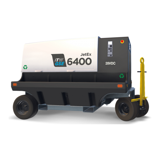
- Page 1 Specification.: DCE6400 28.5 VDC Tier 4 Type: OM2248 AXA Power, Hobart, Houchin, Military and J&B has become ITW GSE. As simply ITW GSE, we still offer the same premium products and service. SAME PEOPLE - SAME PRODUCTS - SAME COMPANY...
- Page 2 Operation Manual - ITW GSE 6400 Tier 4 IMPORTANT NOTICE We recommend that the battery that safeguards GPU settings etc. is changed after 5 years of use in order not to lose data. Diagrams and drawings are subject to change without prior notice.
- Page 3 This manual, including all information contained therein, is exclusive and confidential property of ITW GSE. This manual is not to be copied, reproduced, or delivered or disclosed to others, in whole or in part, except with express written permission of ITW GSE.
- Page 4 Operation Manual – ITW GSE 6400 Tier 4 Safety Warnings and Cautions. WARNING ELECTRIC SHOCK can KILL. Do not touch live electrical parts. ELECTRIC ARC FLASH can injure eyes, burn skin, cause equipment damage, and ignite combustible material. DO NOT use power cables to break load. Prevent tools from causing short circuits.
- Page 5 Operation Manual – ITW GSE 6400 Tier 4 3) Service and Maintenance This equipment must be maintained in good electrical condition to avoid hazards stemming from disrepair. Report any equipment defect or safety hazard to the supervisor and discontinue use of the equipment until its safety has been assured.
- Page 6 Operation Manual – ITW GSE 6400 Tier 4 7) Medical and First Aid Treatment. First aid facilities and a qualified first aid person should be available for each shift for immediate treatment of all injury victims. Electric shock victims should be checked by a physician and taken to a hospital immediately if any abnormal signs are observed.
-
Page 7: Table Of Contents
Operation Manual – ITW GSE 6400 Tier 4 Table of Contents Chapter 1 Description/Operation Chapter-Section/Page# Section 1 Description 1-1/10 1) General 1-1/10 2) Optional Equipment - Appendix A 1-1/10 3) Component Locations 1-1/11 Figure 1-1-1: General Assembly of Generator Set... - Page 8 Operation Manual – ITW GSE 6400 Tier 4 Chapter 2 Servicing / Troubleshooting Chapter-Section/Page# Maintenance Inspection/Check 2-1/53 1) General 2-1/53 2) Maintenance Schedule 2-1/53 Figure 2-1-1 Maintenance Schedule Check Sheet 2-1/54 3) Inspection / Checks 2-1/55 a) General 2-1/55 b) “AR” Checks and Operations (As Required) 2-1/55 c) “BR”...
- Page 9 Operation Manual – ITW GSE 6400 Tier 4 Chapter 2 Servicing / Troubleshooting Chapter-Section/Page# 5) Engine Fuel System 2-2/72 a) Fuel Tank 2-2/72 b) Fuel Water Separator or Lubricity Additive Filter 2-2/72 Figure 2-2-5 Lubricity Filter 2-2/72 c) Primary Fuel Filter...
- Page 10 Operation Manual – ITW GSE 6400 Tier 4 Chapter 3 Manufacturer’s Literature Chapter-Section/Page# Appendix A – Options 3-A/95 Appendix B – Operating in Unusual Service Conditions 3-B/97 Appendix C – Initial Software Installation Procedure 3-C/98 Appendix D – Schematics 3-D/101...
-
Page 11: Description/Operation Chapter-Section/Page
Chapters 1 through 3 of this Operation and Maintenance Manual identify only the basic version of the ITW GSE 6400 Tier 4 generator set. Appendix A contains a list of the rest of the optional equipment that can be ordered with the unit. Each item has a brief description of the optional equipment. -
Page 12: Component Locations
Operation Manual - ITW GSE 6400 Tier 4 3) Component Locations For purpose of orientation when designating RIGHT and LEFT throughout this manual, the radiator is considered to be at the FRONT of the unit and the generator is at the REAR. RIGHT and LEFT are determined by standing at the REAR facing the machine. - Page 13 Operation Manual - ITW GSE 6400 Tier 4 1. Cummins QSF2.8 Engine 5. Output Connections 2. Control Module Assembly 6. Output Contactor (mounted under output table) 3. Battery (inside tray pocket) 7. Coolant fill access cover 4. Battery Disconnect 8. Engine ECM Module...
- Page 14 Operation Manual - ITW GSE 6400 Tier 4 4. Engine Oil Fill Tube 1. Lubricity Additive Fuel Pre-Filter 5. Generator 2. Engine Oil Filter 6. Air Filter Assembly 3. Fuel Filter 7. Tie Down Rings Location (Option) Figure 1-1-3: Main Components of Generator Set (Left Side)
- Page 15 Operation Manual - ITW GSE 6400 Tier 4 1. Oil Drain Valve 2. Muffler Assembly 3. Fifth Wheel Figure 1-1-4: Main Components of Generator Set (Bottom) OM2248 Rev B Page 14 of 104...
-
Page 16: Specifications
Operation Manual - ITW GSE 6400 Tier 4 4) Specifications a) Standards This unit has been designed to be in compliance with the following standards: US EPA Tier 4F/CARB Tier 4F EU Stage IV US MIL-STD-704F, SAE ARP5015 b) Physical Specifications... -
Page 17: Special Features
Operation Manual - ITW GSE 6400 Tier 4 Engine Specifications Manufacturer Cummins, Inc. Model No. QSF2.8 4 cylinder, 4 cycle diesel with turbocharger Type and fuel injection Bore and Stroke 3.7 in x 3.94 in (94 mm x 100mm) Displacement 171 in (2.8 L) -
Page 18: Canopy
Operation Manual - ITW GSE 6400 Tier 4 6) Canopy A composite enclosure, identified as a canopy, provides protection for the engine, generator and electrical controls. The canopy is also designed to reduce the operational noise level in the immediate area of the machine. The canopy is equipped with a bolted latch on the back left corner, which will require the use of a wrench to remove the canopy. - Page 19 Operation Manual - ITW GSE 6400 Tier 4 c) Factory Installed Components and Protective Systems This generator set is assembled with the following components and protective systems: 1) Shutdown/Reset Systems Emergency Shutdown The emergency shutdown switch is to provide instant manual shut off of the generator set by disconnecting power to the ECM through the control box.
- Page 20 Operation Manual - ITW GSE 6400 Tier 4 d) Warnings/Faults The control system reacts appropriately to different detected issues. These types can be generalized between warnings and faults. Warnings are given when the system is able to function but requires servicing/user interaction. Faults are generated when the unit cannot or should not supply regulated power to the aircraft.
-
Page 21: Operator Controls
Operation Manual - ITW GSE 6400 Tier 4 8) Operator Controls The control box is a protected enclosure on the right front panel of the GPU that has a modern graphical display and easy to understand controls. The display allows the user to easily have access to all critical operational information as well as providing textual descriptions of all warnings and failures. - Page 22 Operation Manual - ITW GSE 6400 Tier 4 1) LED Graphical Display 5) Alert/Failure "Red" LED 2) Navigation Keypad 6) Output ON "Green" LEDs 3) Power ON "Blue" LED 7) Current Limit Increase/Decrease 4) Warning "Amber" LED 8) Power ON & Engine Start/Stop (Reset)
- Page 23 Operation Manual - ITW GSE 6400 Tier 4 8: The power ON & Engine Start/Stop button will wake the unit from low-power sleep mode. Pressing it again will begin the start-up sequence for the diesel engine. Pressing it again will shut down the engine.
- Page 24 Operation Manual - ITW GSE 6400 Tier 4 When output power is being provided, the screen will appear as follows: 29.5 V: 560 A 28 VDC Output Activated 1500 The selected current limit is changed by using the up and down arrow keys that are located just below the navigation buttons.
- Page 25 Operation Manual - ITW GSE 6400 Tier 4 Parameters – Menu structure ENGINE Status: Running RPM: 2000 Oil Pressure: 54 psi Temperature: 180 °F ◄ Back ▼/▲ Next/Prev UNIT INFORMATION Highlight the by using the navigation Display FW: 075100 F ◄▼▲►...
-
Page 26: Power Module Assembly
Operation Manual - ITW GSE 6400 Tier 4 9) Power Module Assembly The power module assembly is mounted under the output table which is located at the rear of the machine over the generator. The assembly consists of the rectifier, a current transformer and an output contactor. -
Page 27: Preparation For Use
Operation Manual ITW GSE 6400 Tier 4 Section 2 Preparation for Use, Storage, or Shipping 1) Preparation for use after receipt of unit a) Inspection/Check Inspect unit thoroughly prior to operation. 1) Remove blocking, banding, ties, and other securing material. - Page 28 Operation Manual ITW GSE 6400 Tier 4 9) Check engine lubricating oil level. The oil gauge rod has “H” high-level and “L” low-level marks to indicate operating lubrication oil supply. Oil level should be kept as near the high mark as possible, without going over. See Figure 1-2-1 for capacity.
-
Page 29: Preparation For Storage
Operation Manual ITW GSE 6400 Tier 4 2) Preparation for Storage A generator set in storage or removed from operation, has special precautions that should be taken to protect internal and external parts from rust, corrosion, and gumming in the engine fuel system. -
Page 30: Preparation For Shipment
Operation Manual ITW GSE 6400 Tier 4 c) Long-Term Storage (Over 30 Days) To protect the generator and other electrical components, the complete unit should be packaged using moisture proof packaging and sealing material. Place containers of moisture-absorbing chemicals in unit before packaging. -
Page 31: Operation
Operation Manual – ITW GSE 6400 Tier 4 Section 3 Operation 1) General This section contains information and instructions for safe and efficient operation of the equipment. Operating instructions are presented in systematic sequence of procedures to be followed in supplying 28.5 VDC power. - Page 32 Operation Manual – ITW GSE 6400 Tier 4 5. Alert/Failure "Red" LED 1. LED Graphical Display 6. Current Limit Adjustment Buttons 2. Navigation Keypad 7. Output ON "Green" LEDs 3. Power ON "Blue" LED 8. Output ON/OFF (Reset) * 4. Warning "Amber" LED 9.
- Page 33 Operation Manual – ITW GSE 6400 Tier 4 d) Power Delivery After the engine has started and the display has changed to the output status default screen, insert the aircraft cable into the aircraft. Make sure the cable is inserted until you feel a natural resistance. The plug may be equipped with a 90% insertion switch (split “C”...
- Page 34 Operation Manual – ITW GSE 6400 Tier 4 Discontinue Power Delivery with Unit Shutdown 1) Normal conditions Push the Output ON/OFF pushbutton next to the lit green LED indicator to open the output load contactor. The indicator light next to the button will go OFF, indicating the load contactor has opened and power is no longer being delivered to the aircraft.
- Page 35 Operation Manual – ITW GSE 6400 Tier 4 3) Starting the 28.5 VDC generator set CAUTION The unit can deliver up to 2000 amps of current during the starting of an aircraft engine. This much current will shear the propeller shaft of some aircraft. Therefore, make sure that the current limit is correctly set for the aircraft that is being powered.
- Page 36 Operation Manual – ITW GSE 6400 Tier 4 With the engine running and DC With the engine running and DC power OFF, press the “Up arrow” power OFF, press the “Down to increase the DC current limit. arrow” to decrease the DC current limit.
- Page 37 Operation Manual – ITW GSE 6400 Tier 4 c) Turn off the unit by pressing the 28VDC Start/Stop button. The engine will slow down to 1000 rpm and the display will show the amount of time left in the engine cool down period. Once the cool down period is finished, the engine will turn off.
-
Page 38: Icon Menu
Operation Manual – ITW GSE 6400 Tier 4 3) Icon Menu The Icon Menu can only be accessed from the Default screen. Press the center navigation button ● while in the default menu and hold it down for approximately 5 seconds. If access to the Icon menu has been locked out, the word DISABLED will be displayed when the center button is pressed. -
Page 39: A) View Parameters Menu
Operation Manual – ITW GSE 6400 Tier 4 a) View Parameters Menu The View Parameters Menu is accessed from the Icon screen. Press the center navigation button ● while in default menu and hold down for approximately 5 seconds. The Icon menu is displayed, press the right navigation button to highlight the icon. -
Page 40: B) Setup Menu
Operation Manual – ITW GSE 6400 Tier 4 Setup Menu The Setup Menu is accessed from the Icon screen. Press the center navigation button ● while in the default menu and hold down for approximately 5 seconds. The Icon menu is displayed, press the right navigation button to highlight the Setup icon. - Page 41 Operation Manual – ITW GSE 6400 Tier 4 Setup (continued) – Menu structure Setup Menu 11:27:47 28/06/2013 Settings: Cable Temperature Normally Open Normally Open Normally Closed Refer to Section 3 – 4.7 ◄ Back ● Modify Setup Menu Setup Menu...
- Page 42 Operation Manual – ITW GSE 6400 Tier 4 Setup (continued) – Menu structure Setup Menu 11:27:47 28/06/2013 Settings: Modbus Slave Address 1 – 247 Refer to Section 3 – 4.13 ◄ Back ● Modify Setup Menu 11:27:47 28/06/2013 Settings: LED Brightness...
- Page 43 Operation Manual – ITW GSE 6400 Tier 4 Setup (continued) – Menu structure Setup Menu 11:27:47 28/06/2013 Settings: Language English, French, German, English Italian, Polish, Portuguese, etc. Refer to Section 3 – 4.19 ◄ Back ● Modify Setup Menu 11:27:47...
- Page 44 Operation Manual – ITW GSE 6400 Tier 4 1) 28V Voltage This Setup submenu allows the 28 volt output to be adjusted between 19.0 VDC and 33.0 VDC using the UP and DOWN navigation buttons. (Please note that the acceptable voltage range for all commercial DC powered aircraft is 26V to 29V.
- Page 45 Operation Manual – ITW GSE 6400 Tier 4 5) 28V Interlock Delay a) The default value is 3.5 seconds. For safety, it is recommended to remain at this value or less. b) Go into the Setup Menu and then scroll up or down to the 28V Interlock Delay submenu. Press the center ●...
- Page 46 Operation Manual – ITW GSE 6400 Tier 4 10) Real Time Clock Setup a) This set of sub-menu s allows the user to adjust the internal clock to the correct local time. b) Go into the Setup Menu and then scroll up or down to the Real-Time Clock Setup submenu. Press the center ●...
- Page 47 Operation Manual – ITW GSE 6400 Tier 4 16) Diagnostic Mode Disabled a) This setup submenu is used to assist in the troubleshooting procedure. The default setting is “Disabled”; use the “Engine Only” to verify engine performance. The “Engine Interface” allows read only access to the engine ECM module.
- Page 48 Operation Manual – ITW GSE 6400 Tier 4 To allow the user/operator to use the converter, it is possible to postpone the battery change, by pressing the ◄ (left arrow) push button. The warning message occurs 90 seconds after the unit is powered on or the output contactor(s) are opened (the unit is in Standby Mode).
-
Page 49: C) Black Box
Operation Manual – ITW GSE 6400 Tier 4 Black Box OM2248 Rev B Page 48 of 104... -
Page 50: D) Power Log
Operation Manual – ITW GSE 6400 Tier 4 Power Log The Power Log Menu is accessed from the Icon screen. Press the center navigation button ● while in the default menu and hold it down for approximately 5 seconds. The Icon menu is displayed, press the right navigation button to highlight the Power Log icon. -
Page 51: E) Update/Save Log Menu
Operation Manual – ITW GSE 6400 Tier 4 Update/Save Log Menu The Update/Save Log Menu is accessed from the Icon screen. Press the center navigation button ● while in the default menu and hold it down for approximately 5 seconds. The Icon menu is displayed, press the right navigation button then the down button to highlight the Update/Save Log icon. - Page 52 Operation Manual – ITW GSE 6400 Tier 4 Update/Save Log (continued) – Menu structure 10:30:00 USB MENU 28/06/2013 USB Firmware Update Detected Do you wish to update? 0.0% Press ● to update firmware 10:30:00 USB MENU 28/06/2013 10:30:00 USB MENU...
- Page 53 Operation Manual – ITW GSE 6400 Tier 4 OM2248 Rev B Page 52 of 104...
-
Page 54: Maintenance Inspection/Check
Operation Manual – ITW GSE 6400 Tier 4 Chapter 2 Service and Troubleshooting Section 1 Maintenance Inspection/Check 1) General To make certain the generator set is always ready for operation, it must be inspected and maintained regularly and systematically so that defects may be discovered and corrected before they result in serious damage to components, or failure of the equipment. - Page 55 Operation Manual – ITW GSE 6400 Tier 4 WARNNGHourly Interval 50-150 1000 1500 2000 Calendar Interval Once Daily 3 Mo. 6 Mo. 1 Yr. 1.5 Yr. 2 Yr. Symbol Engine Change Air Cleaner Cartridge Check Coolant Hose and Clamps Check Crankcase Oil Level...
-
Page 56: Inspection/Checks
Operation Manual – ITW GSE 6400 Tier 4 Hourly Interval 50-150 1000 1500 2000 Calendar Interval Once Daily 3 Mo. 6 Mo. 1 Yr. 1.5 Yr. 2 Yr. Symbol Engine (continued) Flush and Change Coolant Drain & Inspect Fuel Tank Check Fan Mounting Spring &... -
Page 57: C) "Br" Checks And Operations (Break-In Period)
Operation Manual – ITW GSE 6400 Tier 4 b) Electrical System (12 VDC) – Check Battery Terminals Periodically, open the battery compartment panel in the right cable tray and visually check the battery cable connectors and battery posts. If corrosion is observed, disconnect the cables and clean battery posts and connectors with a wire brush or special battery post-cleaning tool. -
Page 58: D) "A" Checks And Operations (10 Hours Or Daily)
Operation Manual – ITW GSE 6400 Tier 4 d) “A” Checks and Operations (10 Hours or Daily). 1) Engine. a) Check Crankcase Oil Level. CAUTION DO NOT overfill. DO NOT operate the engine with oil level below the lower bar or above the upper bar on the dipstick. - Page 59 Operation Manual – ITW GSE 6400 Tier 4 Water Drain r Drain Figure 2-1-2 Fuel Lubricity Drain e) Check Fault Code Meter. At each daily start-up, observe the fault screen on the display of the control panel. If the display shows “AIR FILTER CLOGGED”, change the air filter. See Chapter 2-4 for other fault codes.
- Page 60 Operation Manual – ITW GSE 6400 Tier 4 Electrical (28.5 VDC System). a) Check Output Cables and Connector. Check the output cable and plug connection for damaged insulation and contacts each time the connector is detached from the aircraft. b) Monitoring sensors.
-
Page 61: F) "C" Checks And Operations (500 Hour Or 6 Months)
Operation Manual – ITW GSE 6400 Tier 4 d) Check Radiator Core and Hoses. Inspect the radiator core for dirt and debris blocking the fins. Clean as necessary. Check for cracks, holes, or other damage. Check Fuel Pump. iii. Inspect the fuel injection pump mounting nuts for loose or damaged hardware. -
Page 62: G) "D" Checks And Operations (1000 Hours Or 1 Year)
Operation Manual – ITW GSE 6400 Tier 4 1) Electrical (28.5 VDC System). a) Protective Monitoring Circuits. Check operation of all protective monitoring circuits to make certain they will function if a fault occurs in the output circuit. Procedures for testing these circuits are contained in the Adjustment/Test section of this manual. -
Page 63: H) "E" Checks And Operations (1500 Hrs Or 1.5 Year)
Operation Manual – ITW GSE 6400 Tier 4 h) “E” Checks and Operations (1500 Hours or 1.5 Years) 1) Engine. a) Steam Clean Engine. There are several reasons why the engine exterior should be kept clean. Dirt on the outside will enter fuel and oil filter cases and rocker housings when covers are removed, unless dirt is removed first. -
Page 64: I) "F" Checks And Operations (2000 Hour Or 2 Years)
Operation Manual – ITW GSE 6400 Tier 4 “F” Checks and Operations (2000 Hours or 2 Years). 1) Engine. a) Check Vibration Damper. 1. Fan Pulley 4. Belt Tensioner 2. Exhaust Outlet 5. Fuel Pump 3. Alternator 6. V i b r a t i o n D a m p e r Figure 2-1-3 Engine Accessories Check vibration damper for looseness, wobble, chunking and streaking. -
Page 65: J) "G" Checks And Operations (Over 10,000 Hours)
Operation Manual – ITW GSE 6400 Tier 4 “G” Checks and Operations (Over 10,000 Hours). 1) Engine. a. Refer to Cummins Engine Manual for recommended maintenance and overhaul. Engine/ Generator Assembly a. Note: All Generator Overhaul items to be performed by a qualified generator/ motor facility b. -
Page 66: L) (E Lamps And Fuses I )
Operation Manual – ITW GSE 6400 Tier 4 Lamps and Fuses: 1) Check all lamps daily. 2) Check fuses as required. 3) The fuse chart lists all fuses with their location, size, and type. Schematic ITW PART NO. Item Protected... -
Page 67: Maintenance Procedures
Operation Manual – ITW GSE 6400 Tier 4 Section 2 Maintenance Procedures 1) General A suggested maintenance schedule is provided in Section 1 of this Servicing Chapter. Each step of the schedule is also covered in general in Section 1. This Section covers maintenance in more detail, where necessary. -
Page 68: Lubrication
Operation Manual – ITW GSE 6400 Tier 4 2) Lubrication a) General Proper lubrication is one of the most important steps in good maintenance procedure. Proper lubrication means the use of correct lubricants and adherence to a proper time schedule. -
Page 69: D) Changing Engine Oil
Operation Manual – ITW GSE 6400 Tier 4 d) Changing engine oil Change the oil once after the first 50 - 150 hours of use and then every 500 hours of engine operation thereafter. The generator set is equipped with an hour meter to record actual engine operating time. - Page 70 Operation Manual – ITW GSE 6400 Tier 4 Change oil as follows: 1) Provide an open container for catching the old oil below the oil drain plug. Container capacity must be greater than 20 quarts (18.9 liters). 2) The oil drain tube can be found by the muffler at the front of the unit.
-
Page 71: E) Engine Accessories Lubrication
Operation Manual – ITW GSE 6400 Tier 4 e) Engine Accessories Lubrication 1) Alternator Most alternators contain sealed bearings and require no periodic lubrication, however, check to make certain there are no lubrication points on your particular alternator. 2) Starter... -
Page 72: Servicing The Air Cleaner
Operation Manual – ITW GSE 6400 Tier 4 3) Servicing the Air Cleaner A definite time schedule for cleaning or changing the air cleaner cannot be determined because of varying operating conditions. Pull the yellow tab out (about 1 inch) then rotate the hub counter- clockwise about one inch and pull it off of the housing to access the air cleaner filter. -
Page 73: Engine Fuel
Operation Manual – ITW GSE 6400 Tier 4 4) Engine Fuel a) How to select Fuel—Quality The quality of fuel oil used in the diesel engine is a major factor in engine performance and life. Fuel oil must be clean, completely distilled, stable and non-corrosive. -
Page 74: Engine Fuel System
Operation Manual – ITW GSE 6400 Tier 4 5) Engine Fuel System The fuel system consists of five primary components: fuel tank, lubricity filter, primary fuel filter, fuel lift pump, and the fuel return line. The following are maintenance procedures for each of these items. -
Page 75: C) Primary Fuel Filter
Operation Manual – ITW GSE 6400 Tier 4 2) To change the lubricity filter: CAUTION When installing new element, do not over tighten it; mechanical tools may distort or crack filter head. a) Place a pan underneath the fuel filter to catch spilled fuel. -
Page 76: D) Fuel Pump
Operation Manual – ITW GSE 6400 Tier 4 1) To change the fuel filter: a) Shut off fuel valve. b) Place a pan underneath the fuel filter to catch spilled fuel. c) Undo fuel filter with commercial tool and spin off. -
Page 77: G) Draining The Fuel Tank
Operation Manual – ITW GSE 6400 Tier 4 g) Draining the Fuel Tank 1) The fuel tank should be drained and cleaned out annually, when the various fuel filters start to become excessively fouled and before storing the unit for long periods of time. -
Page 78: Engine Cooling System
Operation Manual – ITW GSE 6400 Tier 4 6) Engine Cooling System a) General Cooling system service requires more than maintaining the proper coolant level in the radiator and protecting the system against freezing. Water should be clean and free of any corrosive chemicals such as chloride, sulfate, and acids. -
Page 79: D) Draining The Cooling System
Operation Manual – ITW GSE 6400 Tier 4 CAUTION Never use soluble oil in the cooling system. 1) General. A permanent type antifreeze is recommended for use in the cooling system. CAUTION 1. DO NOT use methanol or alcohol as antifreeze. -
Page 80: F) Cleaning The Radiator Core
Operation Manual – ITW GSE 6400 Tier 4 Cleaning the Radiator Core Blow out accumulated dirt from the radiator core air passages, using water. Bent or clogged radiator fins often cause engine overheating. When straightening bent fins, be careful not to damage the tubes or to break the bond between fins and tubes. -
Page 81: Engine Drive Belt
Operation Manual – ITW GSE 6400 Tier 4 7) Engine Drive Belt a) General The engine cooling fan, alternator, and water pumps are driven by one serpentine belt, which must be replaced if worn or damaged. b) Preparation for Belt Check and Adjustment All driven assemblies must be securely mounted in operating position before checking belt tension. -
Page 82: Replacing The Control Board Battery
Operation Manual – ITW GSE 6400 Tier 4 9) Replacing the Control Board Battery Before removing the Control Board and to avoid any static discharge to the Control Board during the replacement of the battery, please take ESD (Electro Static Discharge) precautions. - Page 83 If the blue LED on the Control Board (location can be found on the Fig. 8.2.3) flashes with approximate 2 flashes per second and the display reports “Communication Error”, the firmware on the Control Board has been erased. The Control Board must be sent to ITW GSE to be reloaded.
-
Page 84: Troubleshooting Procedures
Operation Manual – ITW GSE 6400 Tier 4 Section 3 Troubleshooting Procedures 1) General The Troubleshooting Chart located in this section covers the common faults and malfunctions that can be found during operation or maintenance of this equipment. The chart may not list all faults and malfunctions that can occur. -
Page 85: Check Connections And Leads
Operation Manual – ITW GSE 6400 Tier 4 5) Check Connections and Leads ALWAYS check connections and leads to a component suspected of being faulty. Generally, it is assumed that connections and wiring have been checked first and that power has not been lost as a result of defective wiring or connections. -
Page 86: Cummins Engine Fault Codes & Troubleshooting
Operation Manual – ITW GSE 6400 Tier 4 b) Faults Faults result when any of the fault limits are exceeded, an internal problem, or under certain conditions where an injury to personnel or damage to an aircraft or the GPU could occur. Faults are also stored in the Black Box memory as event records. - Page 87 Operation Manual – ITW GSE 6400 Tier 4 10.0 Troubleshooting Chart Error 1st Corrective 2nd Corrective 3rd Corrective 4th Corrective Error Text in display Description Code Action Action Action Action For faults in this section: Disconnect from Aircraft (if connected). Do not stop engine (if running). Do not let engine start (if not running).
- Page 88 Operation Manual – ITW GSE 6400 Tier 4 Output Current is Remove overload 28V OUTPUT Press ARU Replace Control Replace Interface 4100 over 1200A for 60 and re-engage CURRENT TOO HIGH button to reset Board A1 Board A2 seconds output...
-
Page 89: Engine Controls
Operation Manual – ITW GSE 6400 Tier 4 Engine Controls Trouble, Symptom, Probable Cause Test, Check, and/or Remedy Condition Make sure the Emergency Stop switch is pulled out 1. The engine will not a. Emergency Stop start, and the and switch has been pressed. - Page 90 Operation Manual – ITW GSE 6400 Tier 4 Engine Controls (continued) Trouble, Probable Cause Test, Check, and/or Remedy Symptom, Condition 3. Engine will not a. Low battery output Check the battery and recharge or replace start. Cranking b. Loose starting circuit Check all connections and cables.
- Page 91 Operation Manual – ITW GSE 6400 Tier 4 Engine Controls (continued) Trouble, Symptom, Probable Cause Test, Check, and/or Remedy Condition 8. Engine either goes a. Low fuel was detected or the Add No. 2 diesel fuel. from rated speed to PC1 board could be Replace PC1 Interface board.
-
Page 92: Generator
Operation Manual – ITW GSE 6400 Tier 4 Generator Trouble, Symptom, Probable Cause Test, Check, and/or Remedy Condition 1. Generator does not Problem with brushes Remove, clean, and reinstall the generator brushes, replacing them build up voltage if they are shorter than 7/16 of an inch (11mm). -
Page 93: Load Contactor Operating Circuits
Operation Manual – ITW GSE 6400 Tier 4 Load Contactor Operating Circuits Output 1: Contactor K1 Output 2: Contactor K2 Trouble, Symptom, Condition Probable Cause Test, Check, and/or Remedy 1. Load contactor will not close a. Blown contactor fuse (F3) on Check the fuse and replace if blown. -
Page 94: Protective Circuit
Operation Manual – ITW GSE 6400 Tier 4 Protective Circuit NOTE: Protective monitoring is not completely functional until the load contactor is CLOSED. Since it is not advisable to vary voltages for test purposes while delivering power to an aircraft, the GPU should be connected to a load bank for trouble shooting protective circuits. - Page 95 293194 Diagram, Schematic & Connection Contact ITW GSE if copies of these drawings or manuals are not delivered with the unit (unless otherwise noted above). Refer to Appendix A for specific information on the ITW GSE 6400, 28.5 VDC. Generator Set, optional equipment.
- Page 96 Operation Manual – ITW GSE 6400 Tier 4 This page is intentionally left blank. OM2248 Rev B Page 95 of 104...
- Page 97 Operation Manual – ITW GSE 6400 Tier 4 Appendix A Options The following is a list of options available for the ITW GSE 6400 Generator Set. Option/Features Available Part Description Number DIN40 Towbar 293148 Kit, Clearance Lights 293098 Kit, Beacon, Unit Operating, Amber...
- Page 98 Operation Manual – ITW GSE 6400 Tier 4 This option adds the selected color beacon light to the top of the front canopy. These beacons are delivered with a flashing light. If a steady light is desired, the jumper in the bottom of the light should be cut.
- Page 99 Operation Manual – ITW GSE 6400 Tier 4 Appendix B Operating in Unusual Service Conditions This information is a general guideline and cannot cover all possible conditions of equipment use. The specific local environments may be dependent upon conditions beyond the manufacturer’s control. The manufacturer should be consulted if any unusual conditions of use exist which may affect the physical condition or operation of the equipment or safety to surrounding personnel.
- Page 100 Appendix C Initial Software Installation Procedure Introduction: The ITW GSE 6400 GPU contains two circuit boards that may need to be programmed if they are replaced. (The Control Board (P/N AP-579526) and the Display Board (P/N AP-579536). This document instructs you how to perform this task. Make sure to program the boards with the correct software number and revision.
- Page 101 Operation Manual – ITW GSE 6400 Tier 4 RRRPossible issues that may be encountered during this procedure: Error 201 ”CRITICAL”: Memory Error. Call Technician”. This is caused by the Control Board being unable to read the GPU configuration from the EEprom Board (P/N 579.533).
- Page 102 Operation Manual – ITW GSE 6400 Tier 4 4. Set File system to FAT32 and make sure that Quick Format is NOT clicked. Press start. (The USB should function without issue after the format is complete. This may take several minutes to complete on larger drives.
- Page 103 Interface Board Connector Pin Description Connector Pin Description Connector Pin Description Connector Pin Description ECM (+) Output Voltage (+) Open ECM (+) Output Voltage (‐) CAN L ECM (+) NOT USED NOT USED ECM (‐) Fuel Level (GND) Towbar Status Open ECM (‐) Output Contactor (+) Open ECM (‐) Output Contactor (‐) Open 24VDC NOT USED 90% SWITCH + CAN H Fuel Level INTERLOCK Open J1939‐L NOT USED PLUG TEMP +...
- Page 104 OM2248 Rev B Page 103 of 104...
- Page 105 This formula can be downloaded from www.itwgse.com Forward to Sender: ITW GSE 6400 Information Americas: ITW GSE Americas Company: Model: + 1 941 721 1092 Fax: Serial No.: support@itwgse.us Phone: Error Code: International: ITW GSE ApS Date: ...
Need help?
Do you have a question about the 6400 Tier 4 and is the answer not in the manual?
Questions and answers